

Page 1

User Manual
Intensifier® IP Camera
(O2iB92/O2iD22/O2iD21M/O2iB91M)
Please read this manual carefully before operating the unit and keep it for further reference
4
Page 2

Welcome
Thank you for purchasing this network camera!
Please read this manual carefully before operating the unit and retain it for future reference.
Should you require any technical assistance, please contact Speco Technologies Technical Support.
Important Safeguards and Warnings
1.Electrical Safety
All installation and operation here should conform to local electrical safety codes.
Use a certified/listed 12VDC Class 2 power supply only.
Please note: Do not connect two power supplying sources to the device at the same time; it may result in
device damage! The product must be grounded to reduce the risk of electric shock.
Improper handling and/or installation could run the risk of fire or electrical shock.
Speco Technologies assumes no liability or responsibility for any fires or electrical shock caused by improper
handling or installation.
2.Transportation
Heavy stress, violent vibration or exposure to water is not allowed during transportation, storage and installation.
3.Installation
Handle the device with care. Keep the device right side up.
Do not apply power to the camera before completing installation.
Do not place objects on top of the camera.
4.Repair Professionals
All examination and repair work should be done by qualified personnel only.
Speco Technologies is not liable for any problems caused by unauthorized modifications or user-attempted
repair.
5
Page 3

5.Environment
The camera should be kept in a cool, dry place away from direct sunlight, flammable materials, explosive
substances, etc.
This product should be transported, stored, and used only in the specified environments as stated above.
Do not aim the camera at a strong light source, as it may cause overexposure of the picture, and may affect the
longevity of the camera’s sensors.
Ensure that the camera is in a well ventilated area to prevent overheating.
6. Operation and Maintenance
Do not touch the camera sensor or lens directly.
To clean dust or dirt off of the lens, use an air blower or a microfiber cloth.
6
Page 4

Ta b l e o f C o n t e n t s
1.1 Applications ............................................................................................................................................. 9
1.2 LAN Access to Web Setup Interface .................................................................................................. 10
2 Live View .............................................................................................................................................................. 13
2.1 Menu Bar ................................................................................................................................................. 13
2.2 Sta tus Bar ............................................................................................................................................... 14
3 Recording .............................................................................................................................................................. 15
4 Setup ..................................................................................................................................................................... 16
4.1 PC Path Se tup ......................................................................................................................................... 16
4.2 Basic Setup ............................................................................................................................................. 16
4.2.2 Privacy Mask ............................................................................................................................... 18
4.2.3 Image Setu p ................................................................................................................................ 18
4.2.4 Region of Interest ...................................................................................................................... 20
4.2.5 OSD Setup ................................................................................................................................... 21
4.3 Network Setu p ....................................................................................................................................... 22
4.3.1 IP/Por t Setup .............................................................................................................................. 22
4.3.2 PPPOE Setup ............................................................................................................................... 23
4.3.3 DDNS Client ................................................................................................................................. 24
4.3.4 Ema il Setup ................................................................................................................................. 25
4.3.5 FTP Setup ..................................................................................................................................... 26
4.3.6 SNM P ............................................................................................................................................ 27
4.3.7 UPN P ............................................................................................................................................. 27
4.3.8 HTTPS ........................................................................................................................................... 28
4.3.9 RTSP .............................................................................................................................................. 28
4.3.10 IP Filterin g................................................................................................................................. 29
7
Page 5

4.3.11 Zero Configuration .................................................................................................................. 29
4.4 Event Setup ............................................................................................................................................ 31
4.5 Record ...................................................................................................................................................... 33
4.5.1 Record Schedule ........................................................................................................................ 33
4.5.2 SD card Ma nagement ................................................................................................................ 33
4.5.3 Snapshot Schedule .................................................................................................................... 34
4.5.4 Destination ................................................................................................................................. 35
4.5.5 NAS ............................................................................................................................................... 35
4.6 System ..................................................................................................................................................... 37
4.6.2 System .......................................................................................................................................... 38
4.6.3 Set Time ....................................................................................................................................... 38
4.6.4 Use r Admin ................................................................................................................................. 39
8
Page 6
1
Connection Guide
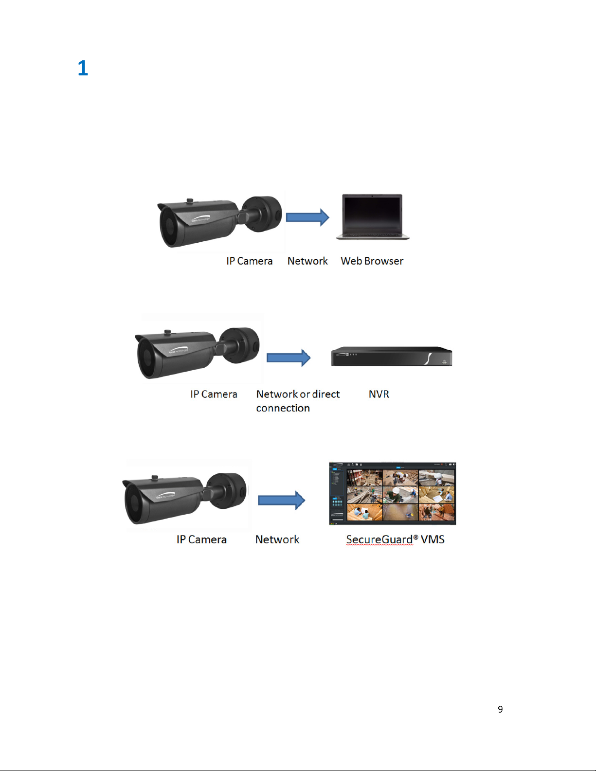
1.1 Applications
Below are the main applications for use with the IP camera:
9
Page 7
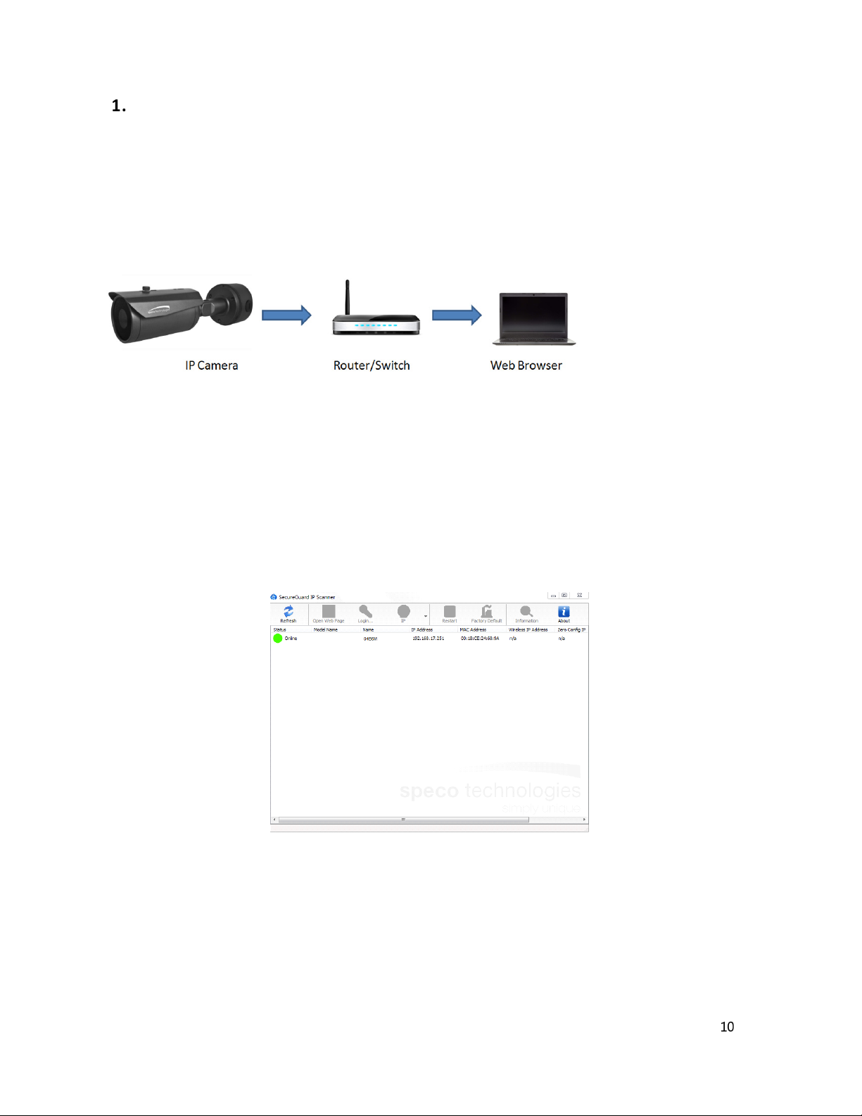
1.2 LAN Access to Web Setup Interface
The IP camera settings can be accessed via a web browser through the LAN using the IP Scanner tool.
Network connection:
1. Make sure that the camera and the PC are connected on the same local network. The camera is set to
DHCP by default and will be assigned an IP address by the DHCP server. Make sure that the local network
has a DHCP server. Routers typically have a DHCP server built in.
2. Install IP Scanner from the CD and run it after installation. IP Scanner is the tool for discovering the IP
cameras on the local network.
3.
In the device list, the IP address, model number, and MAC address of each device will be listed. Select
the applicable device and double click to open up the web viewer. You can also manually enter the IP
address in the address bar of the web browser.
10
Page 8
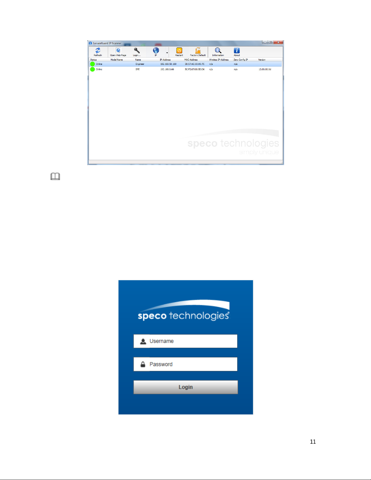
Note
The IP camera will have DHCP turned on by default. If there is no DHCP server available, the
IP camera’s IP address will default to 192.168.0.66.
The login interface is shown below. Default Username and Password: admin/1234. After logging in,
follow directions to install applicable plug-ins for viewing video on the browser.
11
Page 9

After logging in the web interface will be displayed as shown below:
Available functions on the Web Interface:
• Live view
• Save a recording onto the local computer.
• Playback local recordings.
• Modify IP camera parameters, change settings, change video quality and system time.
12
Page 10
Menu Bar
2
Live View
The live view page has two function bars:
Parameter
1.
2.
Description
Status Bar
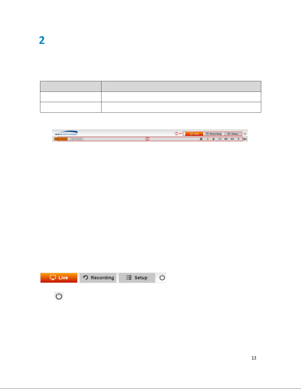
2.1 Menu Bar
Click here to log out
Live: Live view
Recording: Playback of local recordings
Setup: System Setup
13
Page 11
④ ⑤ ③ ⑩
Blue: Sensor alarm has been set up and
activated
Blue: Motion alarm has been set up and activated
Single click on this icon will bring the video to full
screen.
⑧ Schedule
Single click will capture a screenshot. The save directory can
① ② ⑥
⑦
⑧ ⑨
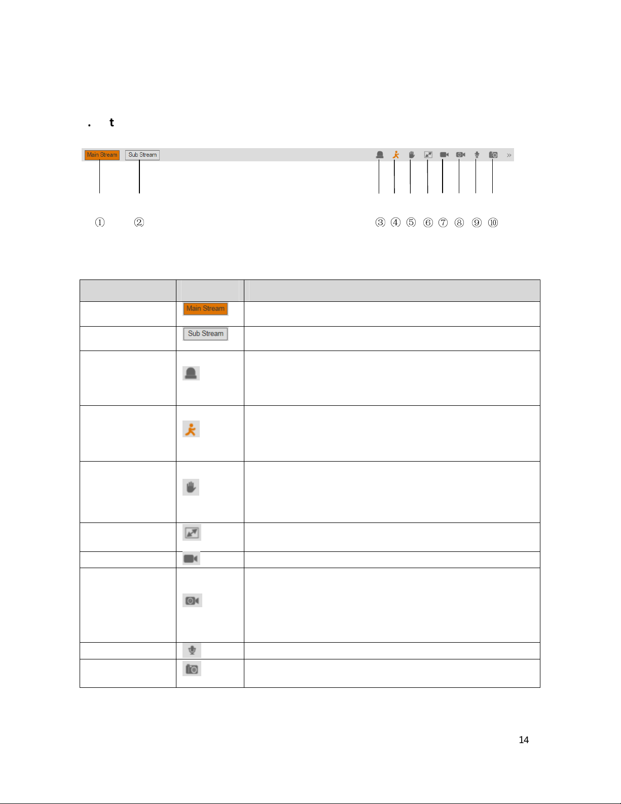
2.2 Status Bar
Parameter icon Description
① Main Stream
② Sub Stream
③Sensor alarm
④Motion Alarm
⑤ Privacy Mask
Alarm
⑥ Full screen
⑦ Manual Record
Recording
Switches to main stream view
Switches to sub stream view
Displays the Sen sor ala rm stat us:
White: Sensor alarm has not been set up
Displays the Motion alarm status:
White: Motion alarm has not been set up
Display the Privacy mask alarm status:
White: Privacy mask alarm has not been set up
Blue: Privacy mask alarm has been set up and activated
Double click on the video or hit “ESC” to exit full screen.
Single click will start the manual record mode on the PC
Shows t he status of Schedule recordin g:
White: Schedule recording has not been set up.
Blue: Schedule recording has been set up and is currently
recording
⑨ Audio
⑩ Screen Capture
Toggle audio on/off
be configured in settings.
14
Page 12

3
Recording
Recordings stored o n SD cards and local PC can be played back via the Recording
interface.
•
Select the “File Type”. Options are “Video” and “Image”.
•
Select the “Data Source”. Options are “SD Card” and “Local”.
•
Select the date and time.
•
Click Search.
•
Click to start playback.
Parameter icon Description
① Slow forward
② Last
③ Stop
④ Next
⑤ Fast Forward
⑥ Capture
⑦ Audio
Slow playback
Play the last video or picture
Stop playback
Play the next video or picture
Speed up playback
Capture a snapshot
Toggle audio on/off
15
Page 13

4
Choose the local recording save directory. “Setup
Click “Save” to save the setting.
> Basic Setup
> File Path”.
and Video stream settings can be
Setup
4.1 PC Path Setup
1.
-> PC Path Setup -
2.
4.2 Basic Setup
4.2.1 Video/Audio Setup
1.
Go to “Setup configured here.
-> Video/Audio Setup”. Audio
16
Page 14

2. Video/Audio Parameters:
The higher the frame rate, the smoother the video. Frame rate is
Resolution
Sets the resolution or size of the image.
Group of pictures. Determines how many frames are allowed between a
Parameter De scription
Sets the video standard
Standard
Pal
NTSC (standard for North America)
Sets the video parameter for each stream typ e:
Stream type
Frame Rate
Main Stream
Sub Stream
measured in fps (frames per second).
Compression Choose the compression codec
Bitrate mode
Bitrate Mode
CBR (constant): The bitrate will stay constant
VBR (variable): Bitrate will be adjusted according to scene
changes.
Video Quality Reference image quality when using VBR.
Bitrate
The actual amount of data the camera is using for streaming. The
higher the bitrate, the better the image quality will be.
“group of pictures”. When a new scene begins in a video, until that scene
GOP
ends, the entire group of frames (or pictures) can be a considered a GOP. If
there is not much movement in the scene, setting a GOP value higher than the
frame rate is fine, potentially resulting in less bandwidth usage. However, if
the value is set too high, and there is a high frequency of movement in the
video, there is a risk of frame skipping.
Audio Enable Toggle audio
Compression Choose the audio codec
3. Click “Save” to save the settings.
17
Page 15

4.2.2 Privacy Mask
1. Go to “Setup > Basic Setup > Privacy Mask”.
2. Check “Enable”.
3. Click “Full Screen” to select the entire area. Click “Clear Screen” to clear the zones.
4. Click and drag to define zones within the image.
5. Click “Save” to complete the privacy mask area configuration.
Note
Up to 4 zones can be defined within the image.
4.2.3 Image Setup
1. Go to “Setup > Basic Setup > Image Setup”.
2.
See the table below for detail descriptions of the image settings.
18
Page 16

50Hz:
reduces flicker in 50Hz lighting conditions.
Parameter Description
Hue Changes the color mix of the image (this can have very dramatic results).
Brightness Changes how bright the image appears to be. The bigger number the brighter.
Contrast The separation between the darkest and brightest areas of the image.
Alters how much color is displayed in the image. The higher the saturation, the brighter
Saturation
and vivid colors will appear to be. If set too high, the image will be over-saturated.
Sharpness Sets the sharpness level of edges.
Preset Mode Sets of pre-determined image settings based on installation environment.
Mirror Change the orientation of the image to be horizontally reversed.
Turn Change the orientation of the image to be vertically reversed.
Camera Angle
Change the orientation of the image to 90°、180°、270° or normal.
FLC (Anti-flicker)
60Hz: reduces flicker in 60Hz lighting conditions. This is common in the United
States.
Outdoor:
disables the anti-flicker function. This is used mostly in outdoor
installations.
ISPDGain Image adjustment parameters, digital automatic gain
Intensify
3DNR Digital noise reduction.
Increase value to capture more light in low light situations. If set too high, there
will be more image blur.
19
Page 17

Turning on the Wide Dynamic Range (WDR) feature improves the overall exposure
Exposure mode
Auto: Sets the exposure level of the camera automatically.
Manual: Adjust shutter speed and gain value of the camera manually.
throughout your entire image. It enables the camera to pick up greater detail in
dark shadows, while making sure that the highlights don't get blown-out.
Digital wide dynamic range (D-WDR) is a software-based technique that optimizes
image quality by adjusting the gamma (γ) value to enhance dark areas.
BLC mode
Back-light Compensation (BLC) optimizes exposure in the foreground and
background of security video. It splits the video scene into different regions and
uses a different exposure for each of these regions. It corrects regions with
extremely high or low levels of light to maintain a normal and usable level of light
for the object in focus.
High light Compensation (HLC) senses strong sources of light in video and
compensates for exposure on these spots to enhance the overall quality.
AGain Image adjustment parameters, analog automatic gain
Color:Only display color image (default for Intensifier®)
Day/Night
B/W:Only display black/white image
Auto:Display color or B/W image according to CDS(lux value)
Time:Display color or B/W image according to setting time
4.2.4 Region of Interest
1. Go to “Setup > Basic Setup > Region of Interest”.
20
Page 18

Show Channel
2. Check “Enable”.
3. Click “Full Screen” to select the entire area. Click and drag within the image to set up the
zones. Up to 4 zones can be defined.
4. Click “Clear Screen” to clear previous settings if needed.
5. Click “Save” to complete the configuration.
Note
Region of Interest can either enhance or reduce the image quality (bit rate) depending on the mode
that’s chosen.
4.2.5 OSD Setup
1. Go to “Setup > Basic Setup > OSD Setup”.
2. Enable and set the desired parameters to be displayed.
Paramete r Description
Show clock Displays or hides the current time
Show Frame Rate Displays or hides frame rate info
Displays or hides the channel nickname. (up to 16 characters)
Name
Show User Info Displays or hides user info. (up to 16 characters)
3. Click “Save” to complete OSD configuration.
Note
Positions of the parameters can be moved around.
21
Page 19

4.3 Network Setup
addresses. Set the device to this mode if there is no DHCP server available.
4.3.1 IP/Port Setup
1. Go to “Setup > Network Setup > IP/Port Setup”.
Paramete r Description
Max connection Up to 10 concurrent device logins are allowed.
Enable or Disable DHCP
Enable DHCP: If the network has a DHCP server built in, it will assign an IP address
DHCP
to the camera.
Disable DHCP (Static): Static networks require all devices to have their IP addresses
manually defined, as there is no device dedicated to automatically assign IP
22
Page 20

IPv4/IPv6
IPv4 is the more common IP address type. A typical IP address might be
This is the access port to log in to the device. It will need to be forwarded properly
Address
“192.168.1.37”or similar. If DHCP mode is used, the IP address assigned by the
network will be shown here. If static mode is used, the IP address can be set here.
The length of the IPv6 address is 128 bits, which is four times the length of the IPv4
address, expressed in hexadecimal and separated by colons. For example, a typical
IP address can be "2001:250:3000:1:1:7 "or similar.
IPv4 Subnet
Gateway
The IPv4 subnet is displayed or set here.
The IPv4 gateway is displayed or set here.
DNS The IPv4 DNS server info is displayed or set here.
MAC Address The unique Mac address of the device is displayed here.
in order to ensure smooth, latency-free communication.
HTTP Port
The default value is “80”, if another device on your network is using this port,
please change to other value.
Example: to log in to the device with the HTTP port set to 82 through a web
browser, type: http://<IPaddress>:82
ONVIF protocol communication port.
Onvif Port
The default value is “85”
Port used for streaming video to various clients
RTSP Port
The default RTSP port is 554
2. Set the desired parameters and click “Save” to complete IP/Port Setup.
4.3.2 PPPOE Setup
1. Go to ”Setup > Network Setup > PPPOE Setup”.
2. Check ”Enable”.
3. Enter the username & password provided by the ISP.
4. Click “Save”. The camera will reboot.
23
Page 21

PPPOE: An advanced protocol that allows the device to be more directly connected via a DSL modem. This is an
> DDNS Client”.
Click ”Save” to complete DDNS Client configuration.
Check to enable DDNS connectivity of the device.
Speco DDNS is the provider.
Enter the nickname to be used for DDNS. The name must be
unique to be used for
Note
option for advanced users only.
4.3.3 DDNS Client
1. Go to “Setup > Network Setup
Paramete r Description
Enable
Provider
Hostname
DDNS.
2.
24
Page 22

4.3.4 Email Setup
Enable Email
Check to enable the email function.
1. Go to “Setup > Network Setup >Email Setup”.
Paramete r De scription
Motion Subject Defines the subject line of the email that is sent for motion events.
Alarm Subject Defines the subject line of the email that is sent for alarm events.
Enter the SMTP server used by the email service to be used.
SMTP Server
For example: “smtp.gmail.com”
SMTP Port
Enter the SMTP port used by the email service.
Sender Address Enter the email address of the sender of the outgoing email.
Sender Password The password for the outgoing email account.
The email address that the device will send emails to.
Recipient Address
Maximum of 4 recipients can be entered.
Test Click Test to verify the email setup.
2. Click ”Save” to complete Email Setup.
25
Page 23

4.3.5 FTP Setup
The default value is “21”
1. Go to “Setup > Network Setup >FTP Setup”.
Paramete r Description
Enable Check to enable the FTP function.
Server Enter the FTP server address.
Port
Enter the FTP port number.
Mode Choose the applicable mode: active or passive.
Username Enter the username used to log in to the FTP server.
Password Enter the password used to log in to the FTP server.
Upload Path Enter the upload folder name here to receive the recorded files.
Test Click Test to verify the FTP setup.
2. Click “Save” to complete FTP Setup.
26
Page 24

4.3.6 SNMP
1. Go to “Setup > Network Setup > SNMP”.
2. Check the corresponding version checkbox according to the version of the SNMP software that will be
used.
3. Set the values for the fields accordingly, based on the values that are used in the SNMP software.
4. Click “Save” to complete SNMP Setup.
4.3.7 UPNP
If this function is enabled, the camera can be quickly accessed through the LAN.
1. Go to “Setup > Network Setup > UPNP”.
2. Select “Enable”.
3. Click “Save” to complete UPNP Setup.
27
Page 25

4.3.8 HTTPS
1. Go to “Setup > Network Setup > HTTPS”.
2. Check “Enable”.
3. Click ”Save” to complete HTTPS Setup.
Note
The check-box enables the use of the HTTPS protocol for accessing the camera. The text field designates the
Hypertext Transfer Protocol Secure (HTTPS) port number. The default value is “443”.
4.3.9 RTSP
1. Go to “Setup > Network Setup >RTSP”.
28
Page 26

2. Check “Enable”.
3. Click ”Save” to complete RTSP Setup.
Note
The RTSP URL for accessing the stream directly from a 3rd party client is shown. An example of a client is VLC
media player.
4.3.10 IP Filtering
1. Go to “Setup > Network Setup >IP Filtering”.
2. Check “Enable” IP Filtering.
3. Enter the IP address to filter. The IP address will be restricted access to the device.
4. Click ”Save” to complete IP Filtering Setup.
4.3.11 Zero Configuration
Zeroconfig can be used to discover the camera on the network when there is no DHCP server available.
1. Go to “Setup > Network Setup >Zero Configuration”.
29
Page 27

2. Enter a Friendly Name for the device to be seen on the network.
3. Click ”Save” to complete Zero Configuration.
Note
Please use Bonjour to search for and access the device
30
Page 28

4.4 Event Setup
4.4.1 Motion Detection Setup
1. Go to “Setup > Event Setup > Motion Detection Setup”.
2. Check “Enable” to turn on the Motion Detection function, then check “Alarm Output” and/or
“Record Video”, depending on the desired action.
Alarm Output: check this function to generate an alarm output signal to trigger connected alarm output
devices.
Record Video: check this function to record video to the local PC when a motion alarm is triggered.
Note
To enable motion recording on Speco’s NVRs and SecureGuard® VMS, just the “Enable” box has to be checked.
3. Click “Regional Edit” to open the image window for modifying the motion detection region.
31
Page 29

Use the mouse to select detection areas.
Sensitivity: the higher the sensitivity, the less movement is required to trigger a motion event.
The lower the sensitivity, the more movement is required to trigger a motion event.
Threshold: the level that the motion detection needs to reach in order to trigger motion detection.
The lower the threshold, the more likely that motion will trigger the event alarm.
Full Screen: one-click to select all areas for motion detection.
Clear Screen: one-click to remove all areas for motion detection.
4. Click “Save” to complete the configuration.
5. Set up values for "Alarm Duration", "Pre-record Time", and "Record Time".
Alarm Duration: when the alarm is triggered, the alarm duration will last for time period specified here
(range from 5 to 300 seconds). The alarm will not be triggered again until this period has ended.
Pre-record Time: this field specifies in seconds how long the surveillance footage is recorded before motion
detection is triggered. This applies to local recording only. For NVR and SecureGuard, the pre-record time is
configured on those respective platforms.
Record Time: this field specifies in seconds how long the surveillance footage will be recorded after motion
detection is triggered.
Note
Setting the “Alarm Duration” time shorter than the “Record Time” is recommended. Otherwise not all the events
might be recorded.
6. Set up the time periods for motion alarms to occur. Only the specified time periods will trigger motion
alarms. Up to 4 periods can be set per day.
7. Click “Save” to complete motion detection configuration.
Note
Privacy Mask and Alarm output can be set up in the same manner as Motion Detection.
32
Page 30

4.5 Record
4.5.1 Record Schedule
1.
Go to “Setup > Record > Record Schedule”.
2. Check “Enable” to set up scheduled recording.
3. Set up the time periods for scheduled recording. Up to 4 periods can be set per day.
4. Click “Save” to complete scheduled recording configuration.
4.5.2 SD card Management
1. Go to “Setup > Record > SD card Management”.
2. After inserting the SD card, click “Refresh” to check the “Total Space”, ”Used Space” and “Available
33
Page 31

Space”.
3. Click “Format” to format the SD card before use. All existing data on the SD card will be erased.
4. Either enable or disable Overwrite depending on the application.
5. Click “Save” to complete SD card Management configuration.
4.5.3 Snapsho t Schedule
1. Go to “Setup > Record > Snapshot Schedule”.
2. Check “Enable” to turn on the snapshot function.
3. Set up the capture time interval. This specifies how often a snapshot will be captured.
4. Set up the time periods for scheduled recording. Up to 4 periods can be set per day.
5. Click “Save” to complete Snapshot Schedule configuration.
34
Page 32

SD Card
Video, alarm and snapshot wi ll save t o an SD card
NAS Video, alarm
and snapshot will save to a NAS
4.5.4 Destination
1. Go to “Setup > Record > Destination”. Recording destinations can be set here for scheduled, motion, and
alarm events.
Paramete r Descriptio n
FTP Video, alarm and snapshot wi ll save t o an FTP s erver
2. Click “Save” to complete Destination configuration.
4.5.5 NAS
1. Go to “Setup > Record > NAS”.
35
Page 33

Parameter Des cription
Server Address Enter the NAS IP address
Remote Directory Enter the target remote directory
2. Click “Save” to complete NAS configuration.
36
Page 34

4.6 System
4.6.1 Maintenance
1. Go to Select “Setup > System > Maintenance”.
Parameter Desc ription
Factory Default Reset the system to factory default settings.
Reboot Reboots the device.
Auto Reboot Schedule an auto reboot for the device.
Download
template file
Current settings of the device can be downloaded as a configuration file. This is
useful if other units of the same model are installed and the same
configuration is desired.
2. Click “System Variable file Upload or System Firmware Upload>Browse”.
3. Select the applicable file and click "Start".
Note
System Variable is used to upload configuration files.
System Firmware is used to update the firmware of the device.
37
Page 35

4.6.2 System
1. Go to “Setup > System > Device Info”.
Paramete r Description
Device Model Model number for the IP Camera
IPC Version IP Camera firmware version
4.6.3 Set T ime
1. Go to “Setup > System > Set Time”.
Paramete r Description
Time zone Set the time zone of the device
Time Manually set the time
38
Page 36

PC Time Sync Syncs the device time with the local PC time
NTP Syncs the device time with a network time server if enabled
NTP Server Enter an NTP server address. The default is “time.windows.com”.
2.
Click “Save” to complete Set Time configuration.
4.6.4 User Admin
1. Go to “Settings > System > User Admin” to add users.
2. Click “Add User” to add a user for the device.
User: user name.
Group: Select between Manager, Supervisor,
and user.
Password: Set/change user password.
Confirm: Confirm password.
3.
Click “Save” to complete User Admin configuration.
Note
Manager: Administrator level – can change all settings and manage users
Supervisor: Can change all settings, except manage users
User: View only
39
 Loading...