

Page 1
Intensifier® IP Specialty Cameras
QUICK INSTALLATION GUIDE
O2iBD3/O2i695/O2iTC23/O2i605CM/
O2i607CM/O2i562/O2i675
Please read this guide carefully before installation and operation of the product.
Page 2
electric shock to persons.
CAUTION
Notice
Thank you for purchasing this product. This guide is designed to be a reference tool for the product. Please read
it carefully before operating the product and retain it for future reference. Should you require any technical
assistance, please contact Speco Technologies Technical Support.
The lighting flash with an arrowhead symbol, within an equilateral triangle is
intended to alert the user to the presence of non-insulated dangerous voltage within
the product’s enclosure that may be of sufficient magnitude to constitute a risk of
The exclamation point within an equilateral triangle is intended to alert the user to
the presence of important operating and maintenance (servicing) instructions in
the literature accompanying the appliance.
CAUTION
RISK OF ELECTRIC
SHOCK
DO NOT OPEN
TO REDUCE THE RISK OF ELECTRIC SHOCK,
DO NOT REMOVE THE COVER (OR BACK).
NO USER SERVICEABLE PARTS INSIDE.
REFER SERVICING TO QUALIFIED PERSONNEL.
INFORMATION
This equipment has been tested and found to comply with limits for a Class A digital device, pursuant to part 15
of the FCC Rules. These limits are designed to provide reasonable protection against harmful interference when
the equipment is operated in a commercial environment. This equipment generates, uses, and can radiate radio
frequency energy and, if not installed and used in accordance with the instruction manual, may cause harmful
interference to radio communications. Operation of this equipment in a residential area is likely to cause
harmful interference in which case the user will be required to correct the interference at its own expense.
WARNING
Changes or modifications not expressly approved by the manufacturer could void the user’s authority to
operate the equipment.
CAUTION –
Do NOT use power source other than that specified.
Do NOT expose this appliance to rain or moisture.
This installation should be made by a qualified service person and should conform to all local codes.
To prevent electric shock and risk of the fire hazards
1
Page 3

PRECAUTIONS
Please read the manual carefully before the installation in order to set up the camera correctly and to obtain
the best picture quality.
Installation and services should only be carried out by an authorized personnel according to local safety
regulations.
If any liquid or solid matter gets into the housing, immediately disconnect the camera from power supply and
have it checked by your authorized dealer before reusing.
Avoid installing the camera in extremely hot or cold places.
If you are not a certified person, never try to dismantle the camera.
To avoid electric shock, never remove the screws or covers. There are no parts inside that need maintenance
by the user. All maintenance should be carried out by qualified personnel.
Avoid installing the camera in a place of high humidity.
Avoid installing the camera at a place exposed to gas or oil.
Don't point the camera directly at sunlight.
Please pay special attention to keep the unit from dropping or external shock during the process of
transportation or handling.
Never try to touch the camera with wet hands. It may cause an electric shock.
Do not expose the camera to radioactivity. It can cause a serious damage on the image sensor.
LIMITATION OF LIABILITY
This publication is provided “AS IS” without warranty of any kind, either express or implied, including but not
limited to, the implied warranties of merchantability, fitness for any particular purpose, or non-infringement of
the third party's right.
This publication could include technical inaccuracies or typographical errors. Changes are added to the
information herein, at any time, for the improvements of this publication and / or the corresponding product(s).
DISCLAIMER OF WARRANTY
In no event shall seller be liable to any party or any person, except for replacement or reasonable maintenance
of the product, for the cases, including but not limited to below :
(1) Any damage and loss, including without limitation, direct or indirect, special, consequential or
exemplary, arising out of or relating to the product.
(2) Personal injury or any damage caused by inappropriate use or negligent operation of the user.
(3) Unauthorized disassembly, repair or modification of the product by the user.
(4) Inconvenience or any loss when images are not displayed, due to any reason or cause
including any failure or problem of the product.
(5) Any problem, consequential inconvenience, or loss or damage, when combined with third party devices.
(6) Any claim or action for damages, brought by any person or organization, due to a violation of privacy when
the surveillance footage, for some reason, becomes public or is used for the purpose other than
surveillance.
2
Page 4

S/N Ratio
More than 50dB
VBR / CBR in H.264
Audio
Compression
G.711
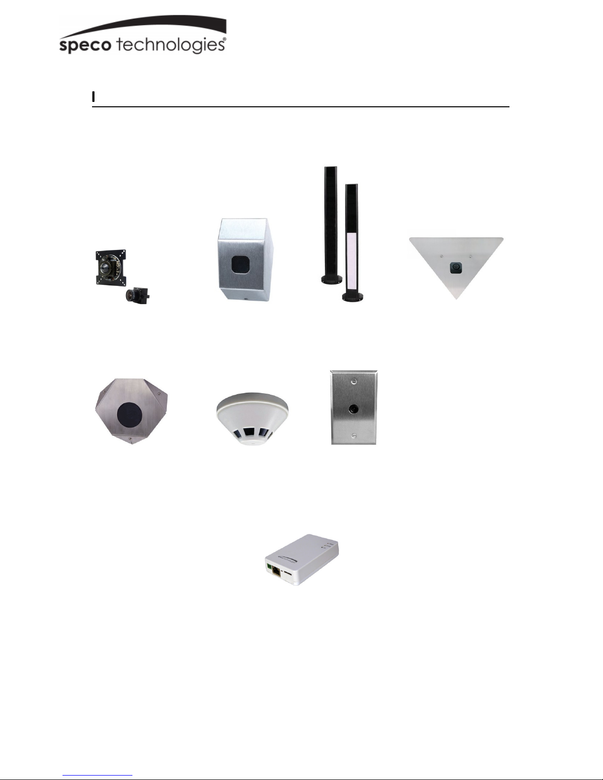
1. PRODUCT OVERVIEW
Key Features
2.0 Mega pixel 1/2.8" SONY progressive scan CMOS image sensor for excellent image quality
Specialty housing design for specific applications
2.9mm wide angle lens or 3.6mm pinhole lens (for O2i562 only)
Support for corridor view (in H.264)
Integrated motion detection with pre- and post-alarm image / video buffering
Supports CBR (Constant Bit Rate) and VBR (Variable Bit Rate) modes
Supports Tampering-Alarm
Controllable frame rate
Privacy Masking up to 8 areas
Built-in standard PoE (802.3af)
HTTPS support
Integrated E-Mail, FTP, DDNS and DHCP client
Specifications
CLASSIFICATION SPEC
ARM1176JZF-STM ( 400 MHz, Instruction cache : 32kbyte,
data cache : 16kbyte, MMU )
General
Image Pickup
CPU
Flash 2Gbit Flash Memory
SDRAM 2Gbit DDR3 Memory
Image Sensor 2.0 Megapixel 1/2.8" SONY progressive scan CMOS image sensor
Total Pixels 1952(H) x 1116(V) 2.18 Megapixel
Effective Pixels 1944(H) x 1104(V) 2.14 Megapixel
Video
Audio
Min. Illumination 0.2Lux
Day & Night Intensifier®
Video Compression H.264 / Motion JPEG
Resolutions Up to 1920 x 1080
Frame Rate
Video Streaming
Image Setting
Backlight WDR (Low / Middle / High)
Shutter Speed 1/30 ~ 1/10000
Noise Reduction 2D / 3DNR
Audio Streaming Two-way
Data / Sample Rate 64Kbps / 8KHz
Audio Input / Output Line in, Line out
H.264 Up to 30fps
MJPEG Up to 30fps with VGA resolution
Supports multi stream with H.264, MJPEG
Adjustable frame rate
Brightness, Contrast, Sharpness
Day & Night
Auto White Balance
Auto Exposure
Privacy Mask
DSS, Corridor-view (in H.264), Mirror / V-Flip, etc.
3
Page 5

HTTPS
encryption
Dynamic IP SPECO DDNS (Free of Charge)
Password protection
Network
System
Integration
Physical
Environment
Specifications are subject to change without prior notice
Security
Supported Protocol HTTP, HTTPS, DNS, RTSP, RTP, TCP, UDP, ICMP, DHCP
Intelligent Video Motion detection 12 x 12 blocks
Alarm Trigger Motion detection, External Input (NO / NC Type)
Video Buffer 5MB pre-alarm and post-alarm-180sec
Firmware Upgrade Remote upgrade via network
Etc 1 x Factory Reset Button
Memory Slot Micro SD
Power Source DC 12V / 1.5A, PoE (Power over Ethernet) : 802.3af
Power Consumption 4W
Main Unit Weight 5 oz
Main Unit Dimensions 3.98(W) x 5.85(H) x 9.54(D)
Housing Weight
Housing Dimensions
Operating
Temperature
User access log
O2i695 (7 oz) / O2iTC23 (5 lbs) / O2i605CM (1.4 lbs) / O2i607CM (1.5
lbs) / O2i562 (5 oz) / O2i675 (4 oz)
O2i695 (2.25”x2.75”x2.5”) / O2iTC23 (24”x2.75”) / O2i605CM
(9”x7”x4”) / O2i607CM (5.1”x3.3”) / O2i562 (3.4”x1.6”) / O2i675
(2.75”x4.25”x2.75”)
14F ~ 122F
4
Page 6

2. NAME AND FUNCTION OF EACH PART
2.1 Main Unit
NO. ITEM DESCRIPTION
1
2
3
4
5
6
7
Power Connector
Network and POE
Connector
Reset Press and hold for 5 seconds to reset to factory default setting
Micro SD slot Insert card with contacts facing up until card clicks in place
Sensor In / Alarm Out
Camera port Connect camera body to main unit
Audio In/Out
1
2 3
4
6
5
DC12V
Caution : If O3FB56M is powered by PoE, do not
plug in DC Jack with active DC power into
DC power connector.
POE (Power Over Ethernet) and LAN cable
From left to right (ABCD)
A: Alarm COM
B: Alarm NO
C: GND
D: Sensor In
From left to right (ABCD)
A: GND (Input)
B: Line In
C: GND (Output)
D: Line Out
7
5
Page 7
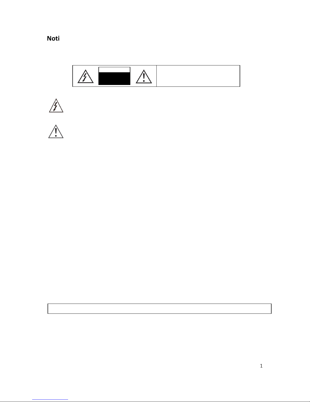
Sensor Input
Connect external alarm sensor. Examples of sensing devices are infrared sensor, motion sensor,
heat / smoke sensor, magnetic sensor, etc. Connect the two wires of the sensor to “Sensor Input”.
The sensor type (NC/NO) can be set in camera setup after logging in. Multiple sensor devices can be connected
in parallel.
SENSOR input and connection of the sensor
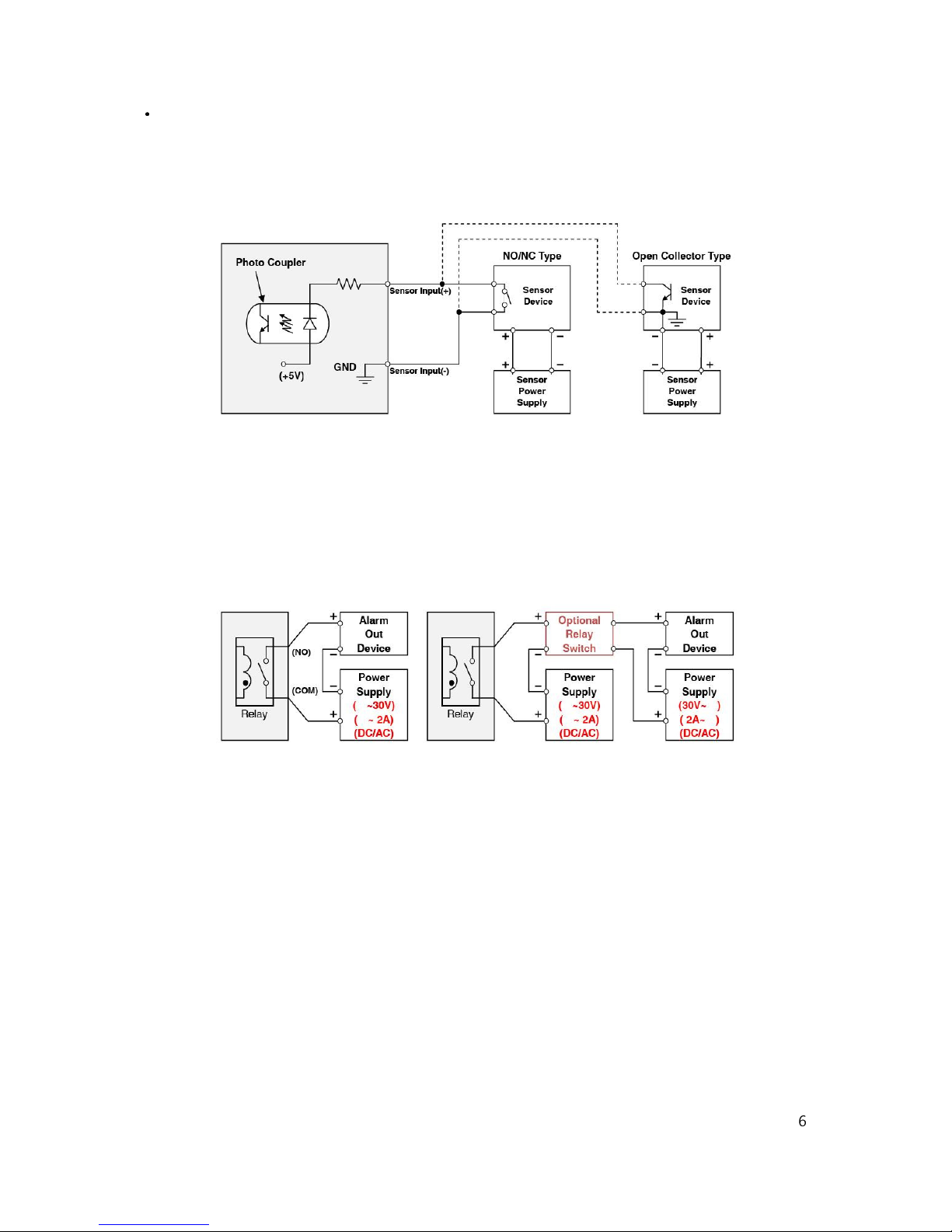
Relay Output
Relay output is provided for connecting alarm devices or for remote on / off control of devices such as light.
Relay is normally open and it will be closed upon alarm annunciation or remote on.
The relay is capable of switching 30V AC/DC, 2A. For the application which needs power switching
beyond this limit, use an additional relay switch as shown below.
Left : switching requirement below 30V, 2A
Right : switching requirement higher than 30V, 2A.
Apply this connection when either voltage or current exceeds the limit.
RELAY Output connection
6
Page 8
3. INSTALLATION & CONNECTION
3.1 Install Camera Housing and Connect to Main Unit
①
Install camera housing as necessary first.
②
Connect the cable from the camera to the main unit.
③
Main unit will provide power to the camera unit.
④
Install the main unit out of reach.
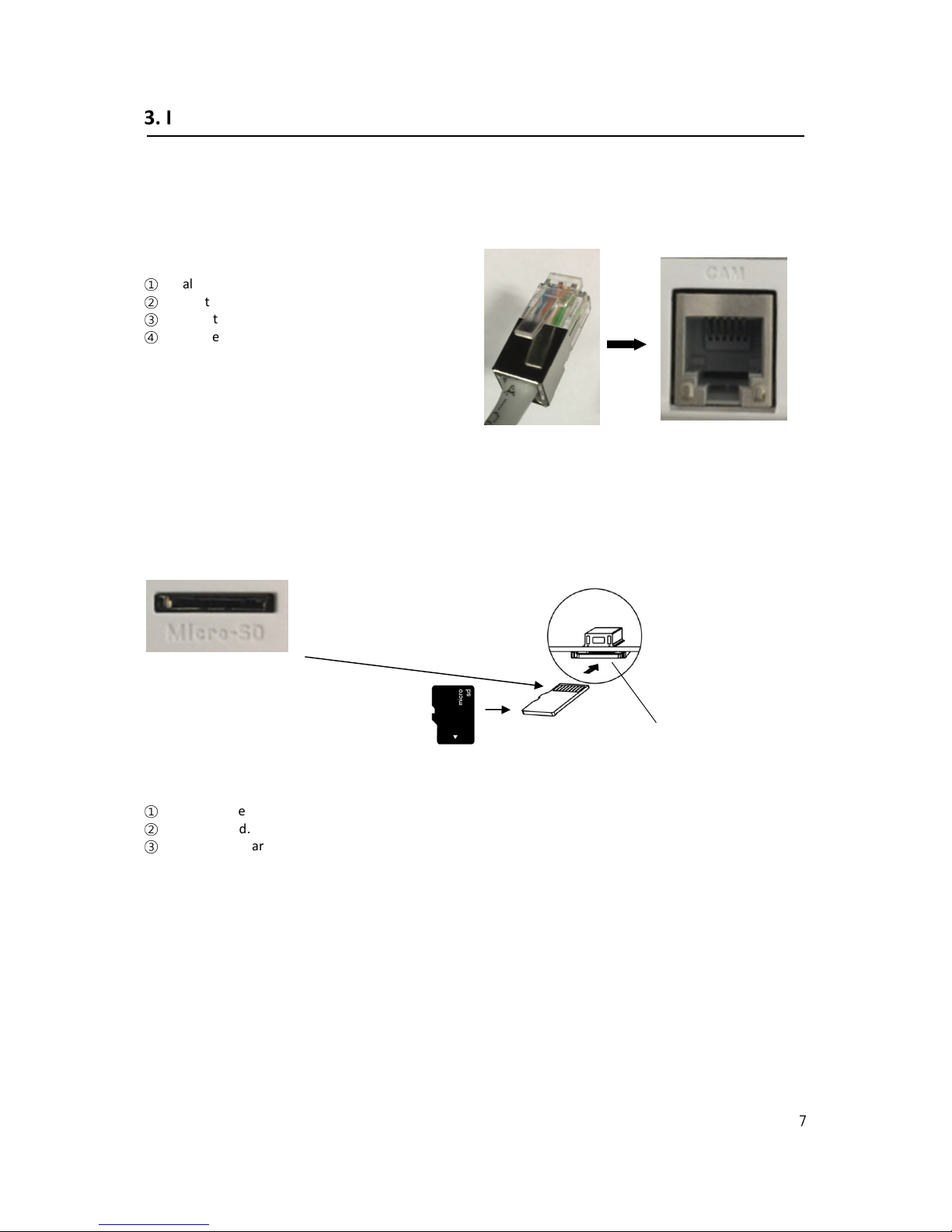
3.3 Install Micro SD Card
SD Card
①
Make sure the contacts are facing up on the Micro SD card.
②
Insert the card.
③
Push until the card clicks into place.
<Caution>
a. Power down the unit before inserting or removing a Micro SD Card.
SD card
Slot
7
Page 9
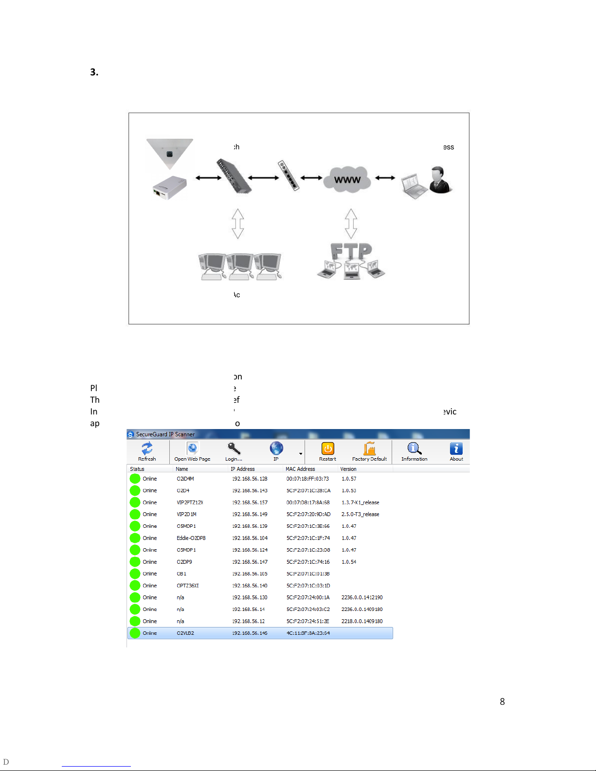
IP Scanner can search for the device on
Please note that only devices that are on the same subnet can be discovered.
The device is set to DHCP mode by default.
In the device list, you can view the IP address, model number, and MAC address of each device. Select the
device and double click to open up the web viewer.
LAN Switch
Local Access E
Router Internet Remote Access
3.4 INSTALLATION EXAMPLE
3.4.1 Installation Example
3.4.2 Connecting to the Network
Open up IP Scanner.
applicable
the local network.
-Mail / FTP
8
Page 10

3.4.3 Accessing the Camera or video server’s Homepage
1) Open the browser and input network camera address in the address bar or double click the device in IP
Scanner.
Input your IP
address here
2) Please input your user name and password when prompted.
3) Default user name is
4) The first time you login to the camera, you will be notified that a ActiveX control is required to be installed.
You need to allow the installation of ActiveX.
admin
and password is
1234
.
9
 Loading...