

Page 1

O2D5M User’s Manual
Network Camera Manual
(O2D5M)
Page 2

O2D5M User’s Manual
2
Directions
Directions
DirectionsDirections
Be careful not to cause any physical damage by dropping or throwing the camera. Especially keep the
device out of reach from children.
Do not disassemble the camera. No after service is assumed when disassembled.
Use only the power adapter provided with the camera.
Be careful to prevent moisture or water penetration into the unit. Attention is needed when installing the
camera. The screw holes for the installation screws and pipe should be maintained water tight during the
whole life time of the product.
All of the electrical connection wires running into the unit should be prepared so that water from the outside
cannot flow into the unit through the surface of the wires. Penetration of moisture through the wire for an
extended period can cause malfunction of the unit or deteriorated image.
Note
This equipment has been tested and found to comply with the limits for a Class A digital device,
pursuant to part 15 of the FCC Rules. These limits are designed to provide reasonable protection
against harmful interference in a residential installation. This equipment generates, uses and can
radiate radio frequency energy and, if not installed and used in accordance with the instructions, may
cause harmful interference to radio communications. However, there is no guarantee that interference
will not occur in a particular installation. If this equipment does cause harmful interference to radio or
television reception, which can be determined by turning the equipment off and on, the user is
encouraged to try to correct the interference by one or more of the following measures:
Reorient or relocate the receiving antenna.
Increase the separation between the equipment and receiver.
Connect the equipment into and outlet on a circuit different from that to which the receiver is
connected
Consult the dealer or an experienced radio/TV technician for help.
Rev 1.0 (Aug. 2015)
Page 3

O2D5M User’s Manual
3
Caution
Any changes or modifications in construction of this device which are not explicitly approved by the party
responsible for compliance could void the user’s authority to operate the equipment.
Revision History
Date Revision Details
Aug 18, 2015 1.0 First manual revision creation.
Rev 1.0 (Aug. 2015)
Page 4

O2D5M User’s Manual
4
Contents
Contents ........................................................................................................................ 4
1. Introduction ............................................................................................................. 5
1.1. Overview ............................................................................................................................... 5
1.2. Specifications ......................................................................................................................... 6
1.3. Applications of O2D5M .......................................................................................................... 7
2. Product Description ................................................................................................. 8
2.1. Contents ................................................................................................................................ 8
2.2. Product Preview .................................................................................................................... 8
2.3. Physical description ............................................................................................................... 9
2.4. Functional Description .......................................................................................................... 11
2.5. Accessories for installation ................................................................................................... 12
3. On Site Installation ................................................................................................. 13
3.1. Installation ............................................................................................................................ 13
4. Getting Started ...................................................................................................... 14
4.1. PC System Requirements ...................................................................................................... 14
4.2. Quick Installation Guide ........................................................................................................ 15
5. Troubleshooting ..................................................................................................... 19
5.1. No power is applied .............................................................................................................. 19
5.2. Cannot connect to the camera .............................................................................................. 20
5.3. Technical Assistance .............................................................................................................. 21
Rev 1.0 (Aug. 2015)
Page 5

O2D5M User’s Manual
5
1. Introduction
1.1. Overview
The O2D5M is a state-of-the-art mega-pixel, dual-codec (H.264, MJPEG) IP/network camera built with embedded software
and hardware technology. It enables real time transmission of synchronized video of up to 1080p and audio data. Remote
clients can connect to O2D5M for real time video/audio data through various client solutions running on PCs and
smartphones. Real time 2-way communication is available through the bidirectional audio communication feature.
Designed to be a stand-alone streaming audio & video transmission device, O2D5M can be applied to various applications
such as video security, remote video monitoring, remote education, video conference or internet broadcasting system.
Vandal proof and weather proof housing will extend the application area to harsh environments of wide temperature
ranges.
Integrated PoE (Power over Ethernet, IEEE 802.3af) will reduce the total cost of ownership by reducing on-site wiring for
installation.
Rev 1.0 (Aug. 2015)
Page 6

O2D5M User’s Manual
6
1.2. Specifications
LENS
Lens Type 3.3~10mm Motorized Focus Lens
Lens Iris Control DC Auto Iris
CAMERA
Image Sensor 1/2.8” 2 Mega Pixel Sony CMOS
Minimum Illumination IR LED Off : 0.5Lux, IR LED On : 0Lux
Scanning Mode Progressive Scan
Dynamic Range (D-WDR) 74.7dB or Higher (90dB or higher)
Electronic Shutter Auto
IR LED 24pcs (850nm)
VIDEO
Compression Algorithm H.264, MJPEG
Compression Resolution 352X240, 704X480, 1280X720, 1920X1080
Bitrate Control H.264-CBR /VBR (up to 12Mbps)
Maximum Frame Rate 30fps @ 1920X1080 + 30fps @ 4CIF
Multi Stream Primary, Secondary, Tertiary
AUDIO
Compression Algorithm G.726 (16KHz), G.711 μ – Law (8KHz)
INPUTS/OUTPUTS
Video Output 1 Composite, 1 Vp-p
Audio Input 1 line in
Audio Output 1 line out
Alarm Input 1 TTL, NC/NO programmable, 4.3V (NC) or 0.3V (NO) threshold, 5 VDC
Alarm Output 1 relay out, NO only, 0.3A @ 125 VAC, 1A @ 30 VDC
Network Connectivity 10/100 Mbps Ethernet
CONNECTORS
Video Output BNC
Audio In/Out Φ 3.5 audio jack
Alarm In Wires
Alarm Out Wires
Ethernet Port RJ-45
GENERAL
Dimensions (Ø x H) 5.1”(W)X3.9”(H)X5.1”(D)
Unit Weight 2lbs
Rev 1.0 (Aug. 2015)
Page 7

O2D5M User’s Manual
7
Operating Temperature 14°F to 122°F (-10°C to 50°C)
Operating Humidity 0% to 90%
Power Supply 12 VDC, PoE (Power over Ethernet) (IEEE 802.3af, Class 3)
Power Consumption Max. 4.8W
Approval FCC, CE, IP66
Specifications are subject to change without notice.
1.3. Applications of O2D5M
Security surveillance (buildings, stores, manufacturing facilities, parking lots, banks, government facilities, military, etc.)
Remote monitoring (hospitals, kindergartens, traffic, public areas, etc.)
Teleconference (Bi-directional audio conference). Remote Learning, Internet broadcasting
Weather and environmental observation
Rev 1.0 (Aug. 2015)
Page 8

O2D5M User’s Manual
the following
M4X25 4EA
L Wrench 1EA
Software & User’s Guide
Quick installation guide
Open Source Guide
PC software to
network and assign IP addresses
SecureGuard™ Plus VMS
PC software to view and record
video from the IP camera.
2. Product Description
2.1. Contents
The product package contains
:
Contents
Main Body
Tools and Mounting
Screws
CD
Quick Reference Guide
GPL License
2.2. Product Preview
Screw
Description Image
O2D5M
, Screw M4X8 3EA
, Core 1EA
Remarks
O2D5M
Vandal Dome IP Camera
IP Scanner
locate IP cameras on the
Page 9

O2D5M User’s Manual
2.3. Physical description
2.3.1. External View
2.3.2. Dimensions
Figure 2-1. External view of O2D5M
Figure 2-2. Dimensions
Page 10
O2D5M User’s Manual
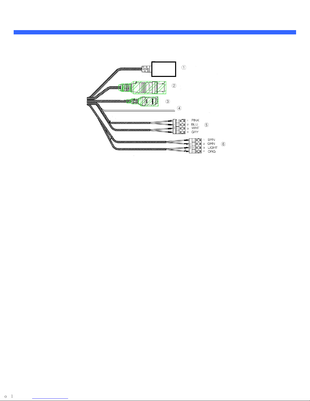
2.3.3. Connector information
①
②
③
④
1. Network Port 2. BNC Video Out 3. Power In
4. Ground 5. Audio In/Out 6. Alarm In/Out
Figure 2-3. Connector information
⑤
⑥
Page 11
O2D5M User’s Manual
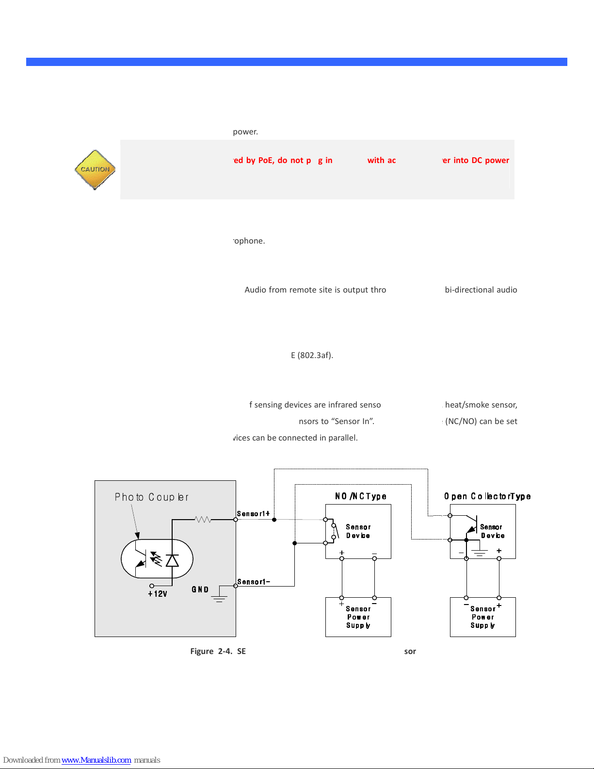
A DC power.
is powered by PoE, do not plug in DC Jack with active DC power into DC
Connect external audio source or microphone.
Connect speakers with built in amplifier. Audio from remote site is output through Line out in bi
PoE (IEEE802.3af)
45) with standard PoE (802.3af).
Connect external alarm sensor. Examples of sensing devices are infrared sensor, motion sensor, heat/smoke sensor,
e two wires of the sensors to “Sensor In”. The sensor type (NC/NO) can be set
admin page. Multiple sensor devices can be connected in parallel.
4. SENSOR input and connection of the sensor
2.4. Functional Description
Power
Power input for supplying 12V 1
Caution: If O2D5M
connector.
Audio (MIC/LINE) IN
Audio (Line) In
mode.
RJ-45 Ethernet (100Base-T) /
100Mbps Ethernet connector (RJ-
SENSOR IN
magnetic sensor, etc. Connect th
in the
power
-directional audio
N O /N C Typ e
N O /N C Typ e
P hoto C oup ler
+ 1 2V
+ 1 2V
+ 1 2V+ 1 2V
G N D
G N D
G N DG N D
Figure 2-
S enso r1 +
S enso r1 +
S enso r1 +S e n sor1 +
S ensor1 -
S ensor1 -
S ensor1 -S ensor1 -
N O /N C Typ eN O /N C Type
S ensor
S ensor
S ensorS ensor
D evice
D evice
D eviceD evice
S ensor
S ensor
S ensorS ensor
P o w er
P o w er
P o w erP ow er
S u p p ly
S u p p ly
S u p p lyS u p p ly
O p en C o llecto rType
O p en C o llecto rType
O p en C o llecto rTypeO p en C o llecto rType
S ensor
S ensor
S ensor S ensor
D evice
D evice
D evice D evice
S e n sor
S e n sor
S e n sorS e n sor
P o w er
P o w er
P o w erP ow er
S u p p ly
S u p p ly
S u p p lyS u p p ly
Page 12
O2D5M User’s Manual
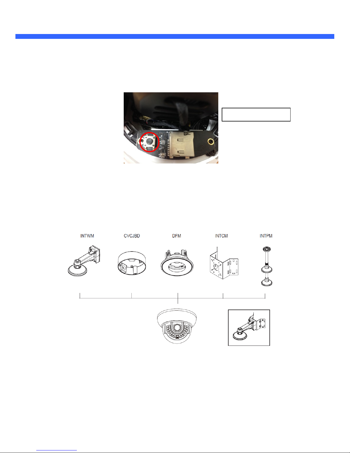
Factory Default Switch
A switch provided for returning the IP camera to factory default state. Unscrew the cover to access the switch.
Press the switch about 5 seconds while power is applied.
Factory default switch
Figure 2-5. Factory Default Switch
2.5. Accessories for installation
Figure 2-6. Accessories for installation of O2D5M
Page 13
O2D5M User’s Manual
3. On Site Installation
Use cables and conduits that are suitable for the installation. Close attention should be paid to the installation so that no
moisture is allowed to penetrate into the unit through the cables or conduits during the lifetime of the product. Products
that have internal parts exposed to moisture due to improper installation are not covered by warranty.
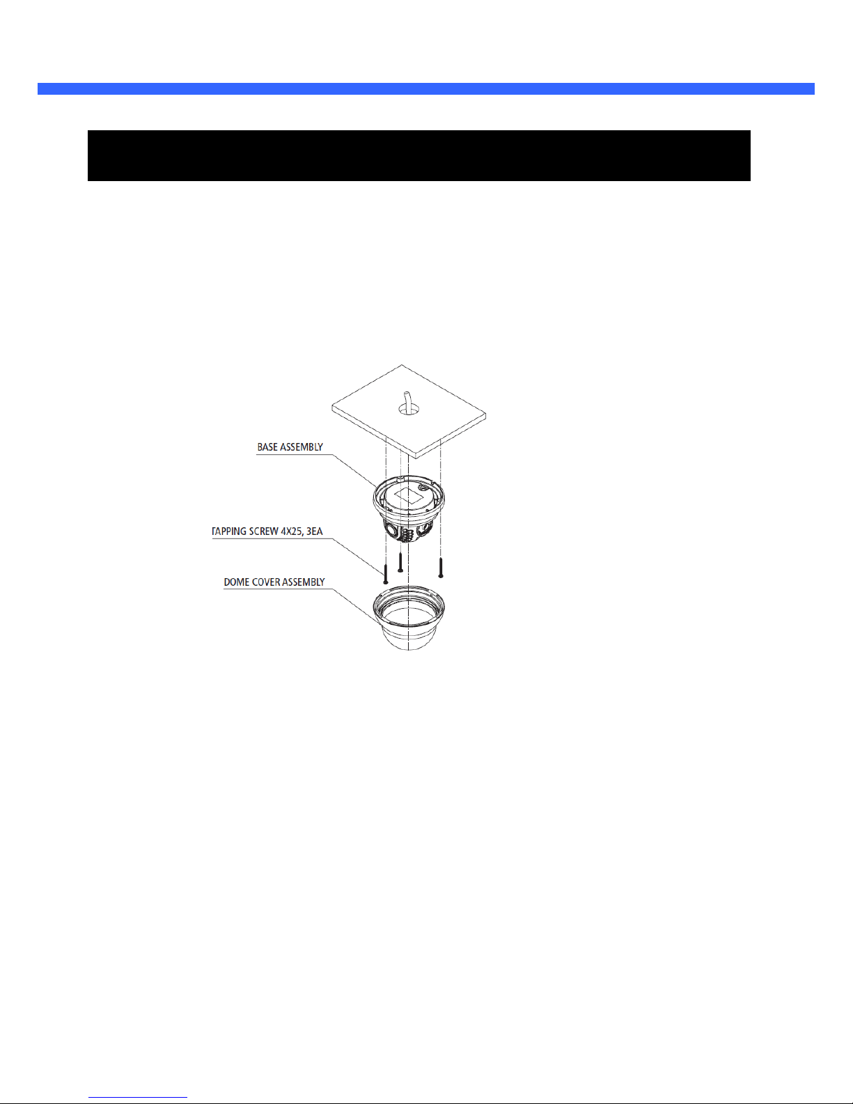
3.1. Installation
1. Screw the bottom cover to the wall or ceiling by using the mounting screws provided with the camera. Use the
mounting template provided with the camera.
2. Connect the external devices, network and power adapter.
3. Adjust the angle of the lens for the proper view angle.
4. Focus and zoom can be adjusted remotely.
5. Tighten the tilt adjustment screw.
6. Screw the dome cover to the bottom cover by using the set screw provided with the camera.
7. Apply power.
WARNING: You might need to reinforce the wall or ceiling. If the wall or ceiling is not strong enough to support the
camera, the camera might fall damaging the camera or causing injuries.
Page 14

O2D5M User’s Manual
14
4. Getting Started
Brief information for the initial operation of O2D5M is provided in this chapter.
4.1. PC System Requirements
Audio/Video streaming data received from O2D5M can be displayed or stored in a PC running client programs. Minimum
requirements of the PC are described below:
Minimum Requirements Recommended Specifications
CPU Intel Core i3 Intel Core i5
Main Memory 2GB 4GB
Operating System* Windows XP Windows 7,8 (64bit)
Web Browser Internet Explorer 8 Internet Explorer 8 or higher
Graphic Card
Video RAM 256MB or more
Resolution 1920x1080
Network 100 Base-T Ethernet 100 Base-T Ethernet
* Operating Systems supported: Windows XP / Vista / 7 / 8
Video RAM 1GB
Resolution 1920x1080
Rev 1.0 (Aug. 2015)
Page 15
O2D5M User’s Manual
15
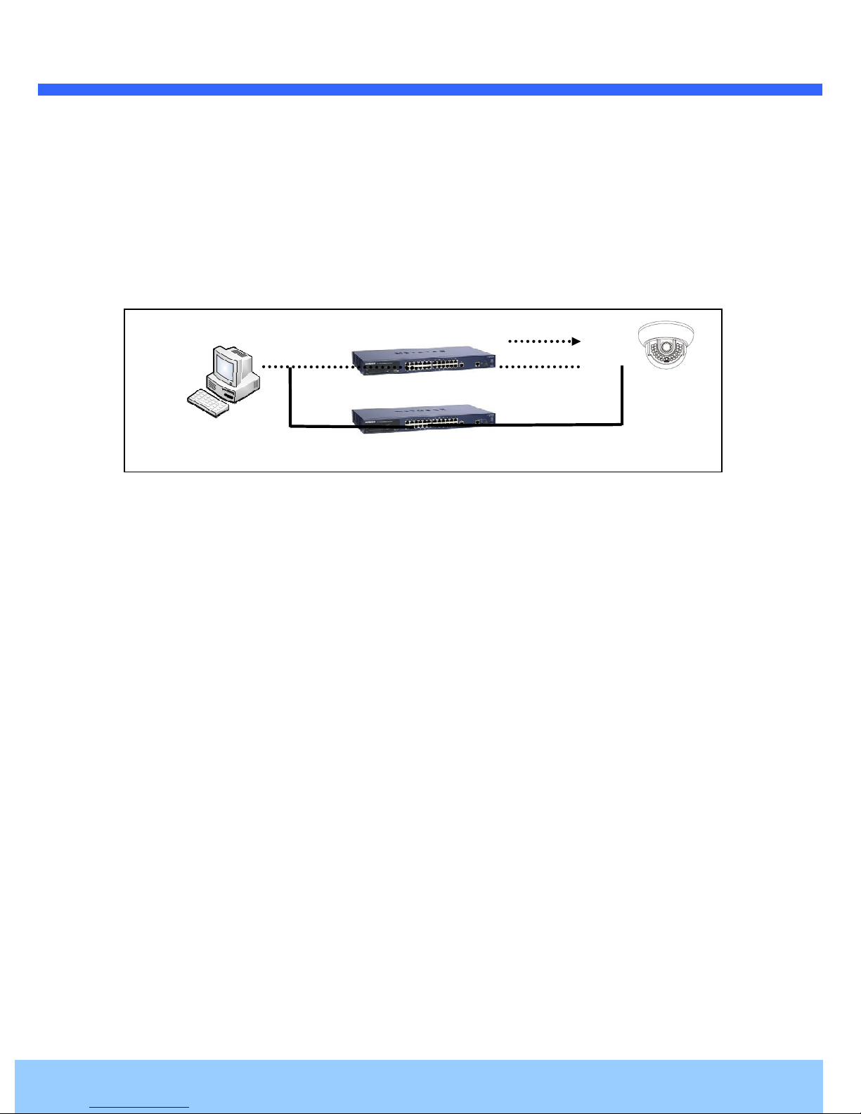
LAN switch with
standard POE
LAN switch
DC adapter
4.2. Quick Installation Guide
1. Connect PC and O2D5M to network.
1) Prepare a PC to run programs for the installation and video connection
2) In the case of using PoE, connect the PC and O2D5M to the network using one of the following ways.
If your LAN Switch does not support standard PoE, connect O2D5M as shown in dotted line in Figure 4-1. The DC
power is applied through DC adapter.
Figure 4-1. Power and network connection
Rev 1.0 (Aug. 2015)
Page 16

O2D5M User’s Manual
IP Scanner is a utility to discover IP cameras on the local network.
low to access the
Install IP Scanner on the PC that will be used on the same local network as the IP camera. IP Scanner can
be found on the CD included in the package or downloaded from specotech.com.
The available cameras on the local
click on the applicable model to launch the camera web viewer
be set to Internet Explorer to view video)
The camera is set to DHCP mode out of the box.
(default browser must
2. Install IP Scanner
Follow the sequence be
i)
ii)
Run IP Scanner
iii)
iv)
Highlight and double-
camera settings
network will show automatically
Page 17

O2D5M User’s Manual
simplest way
Internet Explorer address bar
When prompted, install and allow the Active X controls
, 1234
factory default out of the box. For a more sophisticated target application,
settings
For video connection, enter the IP address of
accessed by clicking on “Setup” in the
Port 80 (default) can be
omitted
3. Remote video connection to O2D5M
1) Connection through Web Viewer
The web viewer offers the
O2D5M in the
to connect to the O2D5M.
as:
[e.g.] Port 80
[e.g.] Port 8080
Note :
as needed
The default login ID and password are admin
4. Additional settings
All parameters of the camera are set to
parameters can be changed through the
web viewer.
.
page. The settings page can be
Page 18

O2D5M User’s Manual
Page 19

O2D5M User’s Manual
19
5. Troubleshooting
5.1. No power is applied
In case of Standard PoE (Power over Ethernet)
Power supply through standard PoE is possible only when the following conditions are met.
1. Standard PoE is supported on the product.
2. The LAN switch supports standard PoE.
Make sure that both the IP camera and the LAN switch support standard PoE (IEEE 802.3af)
In case of DC adapter
If PoE is not applied, the power and network connection should be made through separate cables. Use the
DC adapter recommended by the provider. In case of replacing the DC power supply, make sure that the
power supply meets the power requirement of the IP camera to prevent damage or malfunction.
Rev 1.0 (Aug. 2015)
Page 20

O2D5M User’s Manual
20
1 2
5.2. Cannot connect to the camera
Check the status of the network connection through PING test.
Try the following on your PC:
- Start > Run > Cmd > Ping IP address (Ex : Ping 172.16.42.51)
- If “Reply from ~” message is returned ( in the figure below), the network connection is in normal state. Try
connection to the video again. If the problem persists, or refer to other trouble shooting notes.
- If “Request timed out” message is returned. ( in the figure below), the network connection or network
setting is not in normal state. Check the network cable and settings.
Rev 1.0 (Aug. 2015)
Page 21

O2D5M User’s Manual
If you need any technical assistance, please contact
Description of the problem
lease provide the following
5.3. Technical Assistance
information.
1.
1.
Model name
1.1.
2.
2.
MAC address
2.2.
3.
3.
Purchase date
3.3.
4.
4.
4.4.
5.
5.
Error message
5.5.
Speco’s technical support. P
 Loading...