

Page 1
NVRP4
User’s Manual
Aug. 2011
Page 2
FCC NOTICE
This device complies w ith Part 15 of the FCC R ule s. Op eration is subject to the following two conditions:
(1) this devic e may not cau se har mfu l interference, and (2) this de vice must accept an y interference
received, in clu ding int erferenc e that may cause undes ired operation.
Federal Communications Commission Statement
NOTE - Th is equ ipment has been tested an d found to compl y with the limits for a Class A digital device,
pursuant to Part 15 of th e FCC Rules. Th ese limits are designed to provide reason able prote ction against
harmful interf erence in a residential installatio n. This equipment generat es uses and can radiate radio
freq uen cy energy and, if n ot installed and used in accordan ce with the instructi ons, ma y ca use harmfu l
interference to radio commu nications. However, there is no gu ara ntee that interfere nce will not oc cur in a
part icular inst allation. If t his eq uipment does cause harm ful in ter ference to rad io or tel evi sion reception,
whic h can b e det erm ined by tuning th e equipment o ff an d on, the user is e ncour aged to tr y to corre ct the
interference by one or mor e of the fo ll owing measures:
Reor ient or relocate th e receiving ante nna.
Increase the se paration betw een th e equipment and receiv er.
Connect the equ ipment i nto an outl et on a cir cuit differ ent from that to which the receiver is connect ed.
Consult t he dea ler or a n experienced radio/television te chnician for help.
CE NOTICE
This product is herew ith confirmed to com ply wit h th e require ments set out in t he Council Directives o n
he Approx imation of the law s of t he Member S tates r elating to E lectr omagnetic Compat ibility Direct ive
t
2004 /108/EC.
Warning - Thi s is a Cla ss A product. In a domestic environ ment th is prod uct may c ause radio
interference in which case the user may b e required to t ake adequate measures to correct th is
interference.
DISCLAIMER
No warranty or repres entation, either expressed or implied, is made wit h respe ct to the contents of this
docu mentation, its qua lity, perfor mance, merchantability, or fitness f or a particular purpose. Infor mat ion
presented in this d ocu mentatio n has been carefully c hecked for relia bil ity; however, no responsibility is
assumed for inac curacies. The information conta ine d in this docum entation is sub ject to change witho ut
noti ce.
TRADEMARKS
All other products or corp orate names m entioned in this documentat ion ar e for i den tificati on and
xplanat ion purpose s only, and ma y be tradem arks or registered trade marks of their r esp ect ive ow ners.
e
COPYRIGHT
All rights reserved. No part of this publication may be reproduced, transmitted, transcribed, stored in a retrieval
system, or translated into any language in any form by any means without the written permission of the
manufacturer.
The mark of Crossed-out wheeled bin indicates that this product must not be disposed of with your other household
waste. Instead, you need to dispose of the waste equipment by handing it over to a designated collection point for
the recycling of waste electrical and electronic equipment. For more information about where to drop off your waste
equipment for recycling, please contact your household waste disposal service or the shop where you purchased
the product.
Battery Safety Information
- Stor e t he batteries in a co ol dr y place.
- Do not dispose of used batteries in domestic waste. Dispose of batteries at special collection points or r eturn to point
of sale if applies.
- Remove the batteries during long periods of non-use. Always remove exhausted batteries from the remote control.
Battery leakage and corrosion can damage this remote control, dispose of batteries safely.
- Do n ot mix old and new batteries.
- Do n ot mix different types of batteries: alkaline, standard (carbon- zinc) or rechargeable (nickel-cadmium).
- Do n ot dispose of batteries in a fire. The batteries may explode or leak.
- Never sho rt cir cuit the bat ter y ter minal s.
Page 3

WARNING
TO REDUCE RISK OF FIRE OR ELECTRIC SHOCK, DO NOT EXPOSE THIS
APPLIANCE TO RAIN OR MOISTURE
CAUTION
IF THERE IS ANY DAMAGE, SHORTAGE OR INAPPROPRIATE ITEM IN THE
PACKAGE, PLEASE CONTACT YOUR LOCAL DEALER. WARRANTY VOID FOR
ANY UNAUTHORIZED PRODUCT MODIFICATION.
NOTICE
- INFORMATION IN THIS DOCUMENT IS SUBJECT TO CHANGE WITHOUT
NOTICE.
- THE INFORMATION CONTAINED HEREIN IS TO BE CONSIDERED FOR
REFERENCE ONLY.
Page 4

Table of Contents
Chapter 1 Introduction ....................................................................................... 1
1.1 Package Content ............................................................................................................ 1
1.2 Front Panel ..................................................................................................................... 2
1.3 Back Panel ..................................................................................................................... 2
1.4 Setting Up the NVR Unit ................................................................................................. 3
1.4.1 Connecting Devices ................................................................................................... 3
1.4.1.1 Clamping the power cord ........................................................................................ 4
1.4.2 Connecting the Audio, Sensor and Relay Device ....................................................... 5
Chapter 2 Operating the NVR unit ..................................................................... 6
2.1 First Time Using the NVR Unit ........................................................................................ 6
2.1.1 Using the Virtual Keyboard ......................................................................................... 7
2.2 Familiarizing Yourself with the Buttons in Preview Mode ................................................ 8
2.2.1 Setting Up and Using the Emap ............................................................................... 10
2.2.1.1 To Set Up the Emap ............................................................................................. 10
2.2.1.2 To Use the Emap .................................................................................................. 10
2.2.2 Familiarizing Yourself with the Buttons in PTZ Camera Controller ........................... 11
2.2.2.1 Setup the IP PTZ Camera .................................................................................... 12
2.2.3 Using Event Log Viewer ........................................................................................... 13
2.3 Familiarizing Yourself with the Buttons in Playback Mode ............................................ 14
2.3.1 To Segment and Save the Desired Portion of the Recorded Video .......................... 16
2.3.2 To Bookmark a Video Section .................................................................................. 16
2.3.3 Using the Event Search ........................................................................................... 18
Chapter 3 Customizing the NVR System ........................................................ 19
3.1 System Setup ............................................................................................................... 19
3.2 Camera Setup .............................................................................................................. 25
3.2.1 To Setup the IP Camera ........................................................................................... 25
3.2.2 To Setup Camera from the Remote DVR ................................................................. 29
3.3 Recording Setup ........................................................................................................... 30
3.4 Network Setup .............................................................................................................. 32
3.5 Schedule Setting .......................................................................................................... 35
3.6 Backup Setup ............................................................................................................... 36
3.6.1 Using QPlayer to Playback Backup Video ................................................................ 37
3.6.2 To Cut and Save the Portion of the Recorded Video ................................................ 40
3.6.3 Using the Visual Search ........................................................................................... 40
3.6.4 To Search Using the Event Search .......................................................................... 41
3.6.5 To Search Using the Intelligent Search .................................................................... 42
3.7 Sensor Setting .............................................................................................................. 43
3.8 Relay Setting ................................................................................................................ 44
3.9 Alarm Setting ................................................................................................................ 45
Page 5

3.10 User Setup .................................................................................................................... 49
Chapter 4 Using the USB Playback Console .................................................. 51
4.1 Recommended system requirements ........................................................................... 51
4.2 Installing the USB Playback Console............................................................................ 51
4.3 Running the USB Playback Console ............................................................................ 52
4.3.1 To Cut and Save the Portion of the Recorded Video ................................................ 54
4.3.2 Playback DVR Recorded File from Hard Disk .......................................................... 55
4.3.3 Playback Backup File(*.dvr) ..................................................................................... 56
4.3.4 To Backup Recorded File ......................................................................................... 57
Chapter 5 iEnhance .......................................................................................... 58
5.1 To Use iStable ............................................................................................................... 59
Chapter 6 Using the Remote Programs .......................................................... 60
6.1 Familiarizing Yourself with the Buttons in WebViewer .................................................. 61
6.1.1 To Setup Remote System Setting ............................................................................ 63
6.1.1.1 System Setting ..................................................................................................... 63
6.1.1.2 Camera Setting ..................................................................................................... 64
6.1.1.3 Record Setting ...................................................................................................... 67
6.1.1.4 Network Setting .................................................................................................... 69
6.1.1.5 Alarm Setting ........................................................................................................ 71
6.2 Familiarizing Yourself with the Buttons in WebViewer PTZ ........................................... 76
6.3 Familiarizing Yourself with the Buttons in Remote Console .......................................... 77
6.3.1 To Setup Remote Console Setting ........................................................................... 78
6.3.2 Familiarizing Yourself with the Buttons in PTZ Camera Controller ........................... 79
6.4 Using the Remote Playback ......................................................................................... 80
6.4.1 Familiarizing Yourself with the Buttons in Local Playback ........................................ 81
6.4.1.1 To Cut and Save the Wanted Portion of the Recorded Video ............................... 83
6.4.2 Familiarizing Yourself with the Buttons in RealTime Playback ................................. 84
6.4.3 Familiarizing Yourself with the Buttons in Download and Playback .......................... 86
Chapter 7 U
7.1 Using PDAViewer to Access NVR Server ..................................................................... 87
7.1.1 To install PDAViewer thru ActiveSync ....................................................................... 87
7.1.2 To install PDAViewer from the Internet ..................................................................... 87
7.1.3 To Use the PDAViewer ............................................................................................. 89
7.1.4 To Playback in PDAViewer ....................................................................................... 90
7.2 Using JavaViewer to Access NVR Server ..................................................................... 91
7.2.1 To install JavaViewer from the NVR Server .............................................................. 91
7.2.2 To Use the JavaViewer............................................................................................. 92
7.3 Using iPhone to Access Remote NVR Server .............................................................. 93
7.3.1 Download the SpecoPC Application ......................................................................... 93
I. Download through the PC..................................................................................... 93
II. Using iPhone to Download ................................................................................... 94
7.3.2 Using the SpecoPC Application ................................................................................ 94
sing Mobile Device to Access NVR Server ................................... 87
Page 6

Chapter 8 Web Tools ........................................................................................ 96
8.1 Dispatch Server ............................................................................................................ 96
8.1.1 To Run Dispatch program:........................................................................................ 96
8.2 Remote Setup ............................................................................................................... 97
8.2.1 To Add NVR server ................................................................................................... 97
8.2.2 To Setup Remote System Setting ............................................................................ 98
8.2.2.1 System Setting ..................................................................................................... 98
8.2.2.2 Camera Setting ..................................................................................................... 99
8.2.2.3 Record Setting .................................................................................................... 102
8.2.2.4 Network Setting .................................................................................................. 104
8.2.2.5 Alarm Setting ...................................................................................................... 106
8.3 Remote Backup .......................................................................................................... 110
8.3.1 To back up the recoded data from the NVR server: ............................................... 110
Appendix A Registering Domain Name ............................................................................... 113
Page 7
i
Chapter 1 Introduction
NVRP4 brings you the newest version of a true Network Video Recorder. With its compact size, it
provides 4 channel video and audio inputs and supports full range of IP cameras from all major
manufactures worldwide, accepting H.264, MPEG4 and MJPEG video streaming formats.
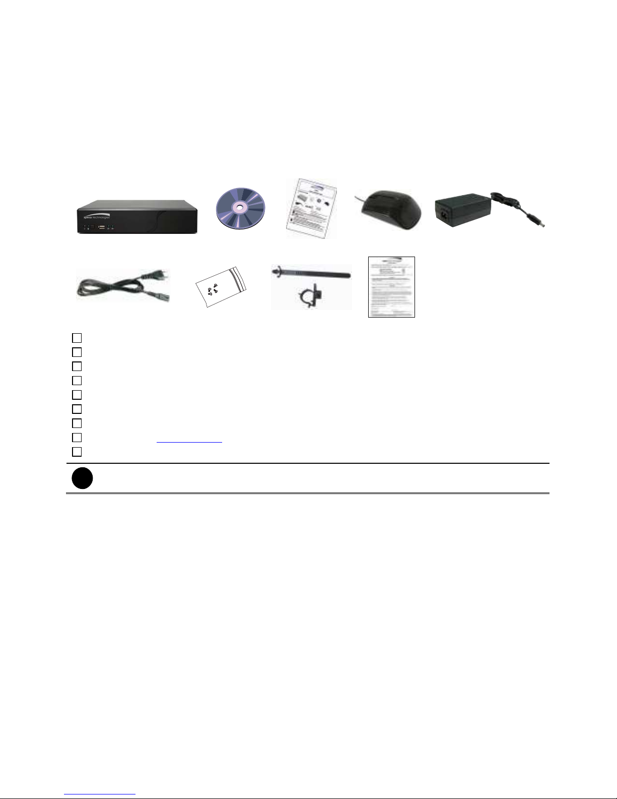
1.1 Package Content
(1)
(6)
(1) NVRP4 unit
(2) Software CD (User Manual included)
(3) Quick User Guide
(4) USB optical mouse
(5) Power Adapter
(6) Power Cord
(7) Screws for hard disk installation
(8) Clamp (see Chapter 1.4.2.1 for installation)
(9) Warranty card
If there is any damage, shortage or inappropriate item in the package contents, please contact your local
dealer.
(7)
(2)
(3)
(8)
(4)
(9)
(5)
1
Page 8
-
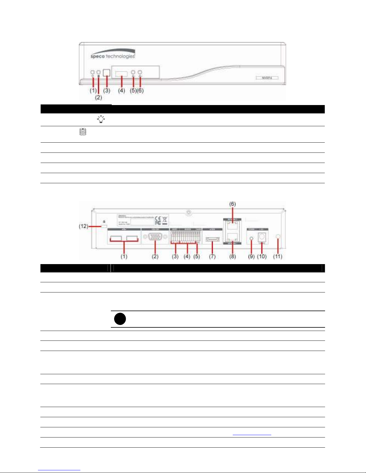
1.2 Front Panel
Name Function
(1) NVR Power LED
(2) HDD LED
(3) IR Sensor Receive signal from the remote control to operate the unit
(4) USB 2.0 Port For flash drive/DVD-ROM connection
(5) Network 1 Indicator Indicate the status of network 1 (Port LAN 1)
(6) Network 2 Indicator Indicate the status of network 2 (Port LAN 2)
Light when the unit is power on
Indicate the hard disk running state. Light is on when the HDD is running
(Read/Write)
1.3 Back Panel
Name Function
(1) 2 x USB 2.0 ports For USB keyboard, mouse, and other USB device connections.
(2) VGA Out Output the video signal to a CRT or LCD monitor
(3) Audio In/Out - Audio In: Input the audio signal from audio input device such as microphone
- Audio Out: Output the audio signal to a audio out device such as speaker
i
(4) Sensor In Support 4 sensor devices
(5) Alarm Out Support 1 relay device (Relay: 1A @ 125VAC / 30VDC)
(6) Gigabit LAN 2 port - To connect the switch of your network for internet connection, remote accessing,
- LAN 2 support Static, DHCP, or PPPOE mode.
(7) e-SATA port For connecting external RAID
(8) Gigabit LAN 1 port - LAN connection only but default assign as a DHCP service port. User also can
LAN 1 supports Static or DHCP mode.
(9) Power button Press it to power on the NVR unit.
(10) 12V DC Power cable connection
(11) Clamp hole For clamp plug-in to clamp the power cord (see Chapter 1.4.2.1)
(12) Lock hole For locking the NVR unit to avoid NVR unit been taken.
The audio input/output device has its own power supply where necessary.
and connection of IP camera.
connect the IP camera through the Ethernet cable.
2
Page 9
i
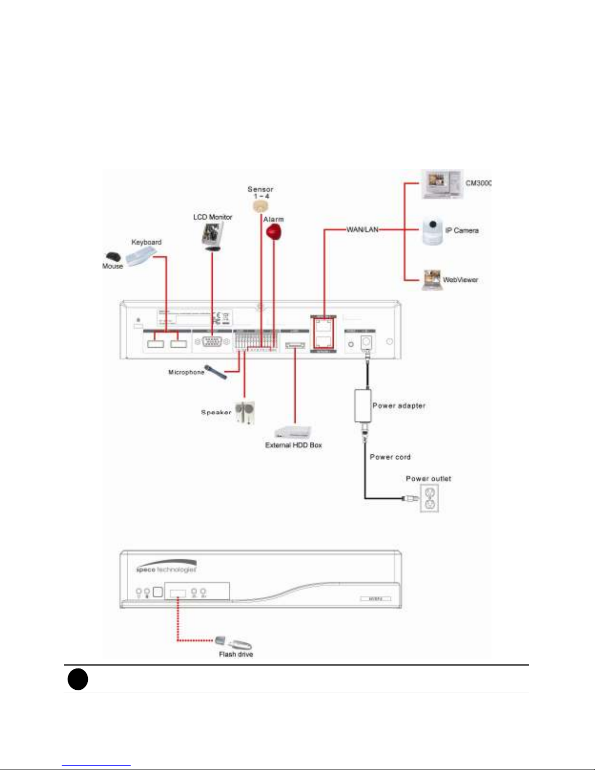
1.4 Setting Up the NVR Unit
1.4.1 Connecting Devices
The back panel of the NVR unit, user can connect 4 sensor devices, 1 alarm device, audio input/output
device and an external HDD storage device. Two Gigabit LAN ports are provided to support the balance
of the network bandwidth for IP camera connection and remote accessing. The USB ports can connect
the mouse and keyboard for more easily to operate NVR server.
Follow the illustration below to make the connection:
Both LAN ports can be used for connecting with IP camera and remote access.
3
Page 10
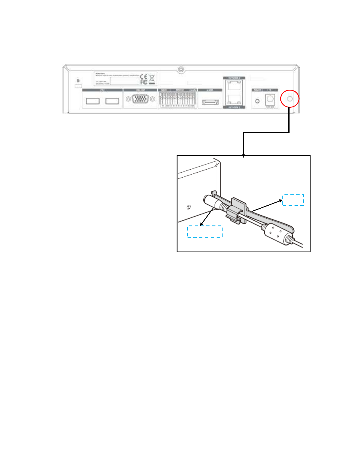
1.4.1.1 Clamping the power cord
User can use the clamp that is included in the package to clamp the power cord to prevent the power cord
from sliding out.
Power cord
Clamp
4
Page 11
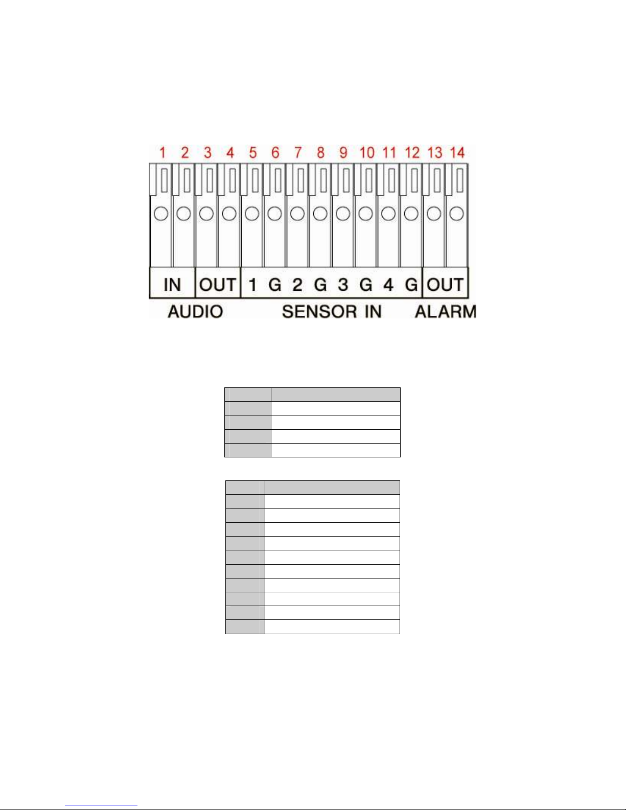
1.4.2 Connecting the Audio, Sensor and Relay Device
The Sensor, Alarm, and audio port enable you to connect 4 sensor inputs, 1 relay output, and 1 audio in
and 1 audio out device. Just connect the external sensor, relay, and audio in/out device pin directly to the
pinhole.
Check the table below and locate which pinhole is assigned to sensor input, relay output, and audio
in/out.
The signal from the sensor (i.e. infrared sensors, smoke detectors, proximity sensors, door sensors, etc.)
is being transmitted to the unit and this triggers the system to respond and send signal to relay device
(i.e., alarm, telephone etc).
Audio in and out pinhole:
Sensor and Alarm pinhole:
Pin # Definition
1 Audio input signal
2 Audio Ground signal
3 Audio output signal
4 Audio Ground signal
Pin # Definition
5 Sensor 1 signal
6 Sensor 1 Ground signal
7 Sensor 2 signal
8 Sensor 2 Ground signal
9 Sensor 3 signal
10 Sensor 3 Ground signal
11 Sensor 4 signal
12 Sensor 4 Ground signal
13 Alarm signal
14 Alarm signal
5
Page 12
Chapter 2 Operating the NVR unit
2.1 First Time Using the NVR Unit
1. Connect the mouse to the USB port located at front panel of the NVR unit.
2. Using the mouse and virtual keyboard (see also Chapter 2.1.1) to operate the NVR system.
3. Power on the NVR unit.
4. For security purposes, the NVR system would require you to enter User ID and Password before it
can be accessed. (If this is the first time, enter the default ID [
admin
] and password [
admin
]).
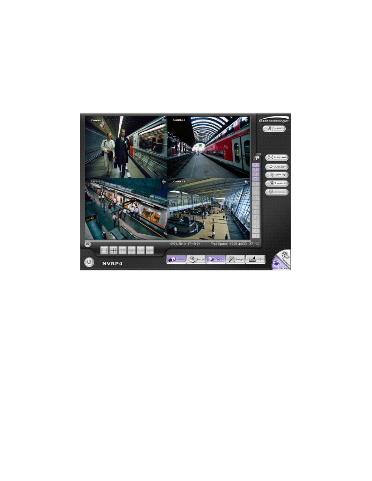
Preview User Interface
5. Formatting the hard disk.
a. Click
b. Click
c. Select the hard disk from device list and select
d. Click
e. When formatting is done, click OK.
6. Setup the correct date and time.
a. Click
b. In
c. Select the date and adjust the time, and then, click OK.
7. Connect the IP camera.
a. Click
b. Select camera channel and type of camera – IP Camera
c. And then, enable the camera
d. Click IP
e. Enable
f. Enter
g. Enter ID and
h. Click OK.
Setup
System
Format
Setup
Time
Setup
IP address
and enter the password
→
button to start formatting
and enter the password
section, click
→
Setting
Protocol
password
Add
Setting
Camera
, and then, select
or
of IP camera.
URL
if IP camera’s access authority is required.
button of
System Time
protocol, mode, video format
Format type
.
, and
channel
of IP camera.
6
Page 13

i. Repeat step 7 to connect to another IP camera.
2.1.1 Using the Virtual Keyboard
User can use the Virtual Keyboard when the keyboard is not available. Just click or right-click on the
screen to call out the virtual keyboard. For uppercase, click
button. To exit, click
Caps
Esc
.
7
Page 14
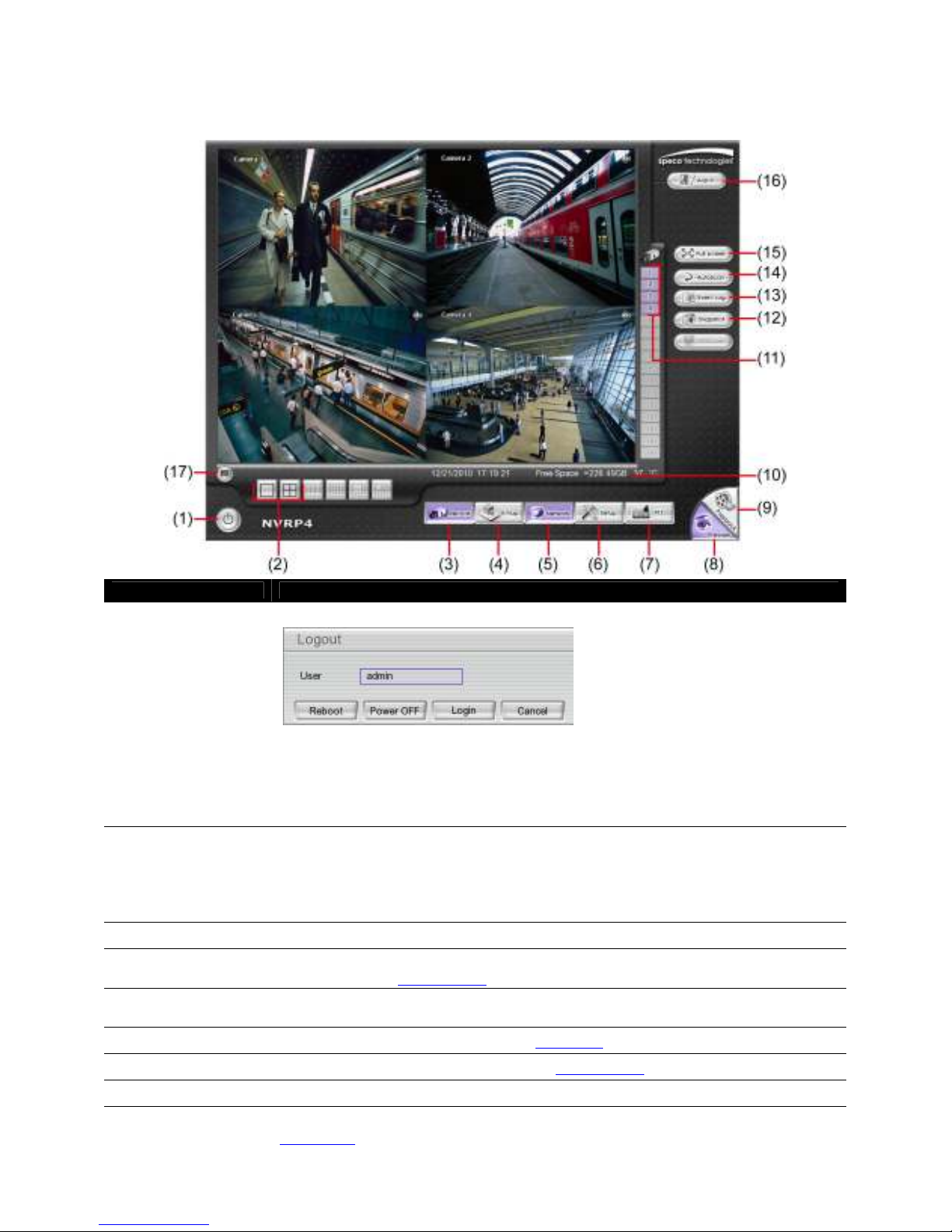
2.2 Familiarizing Yourself with the Buttons in Preview
Mode
Name Function
(1) Exit
(2) Split Screen Mode
(3) Record
(4) EMap
(5) Network
(6) Setup
(7) PTZ
(8) Preview
(9) Playback
Call up the Logout dialog box.
In the logout dialog box, you may do the following:
- Reboot: To restart the NVR system. It is required to enter the password
- Power OFF: To shutdown the NVR system.
- Login: Using different ID to login to NVR system.
- Cancel: To close the logout dialog.
Select from 2 different split screen types to view all the cameras or one camera on a
single screen. It also allows you to switch and view different camera number.
When user is in single screen mode, user can right-click and drag a square on the
area you want to enlarge the view. Right-click on the screen again will return to the
normal view.
Start/stop video recording.
Display the map in each area, and the location of camera/ sensor/ relay and the
warning (see also Chapter 2.2.1).
Enable/disable remote system access. This feature allows you to access NVR server
from a remote location via internet connection. The default is disabled.
Configure the system settings (see also Chapter 3)
To call out the PTZ control panel (see also Chapter 2.2.2)
Switch to Preview mode. This allows you to view live camera display.
Switch to Playback mode. This allows you to view the recorded video file. (See also
Chapter 2.3).
8
Page 15
Name Function
(10) Status bar
(11) Camera ID
Display the recoding date, time and hard disk space of NVR unit.
Show the number of cameras that are being viewed. When you are in single screen
mode, click the camera ID number to switch and view other camera.
(12) Snapshot
(13) Event log
(14) AutoScan
(15) Full screen
Capture and save the screen shot in *.jpg format.
Show the record of activities that take place in the system. (see also Chapter 2.2.3)
Start/Stop video screen cycle switch.
View in full screen. To return, press the right button of the mouse or ESC on the
keyboard or click the arrow icon.
When you switch to full screen in multiple-screen mode, Left click to toggle to only
display one of the video in the multiple-screen mode or all.
(16) Alarm
Alert and display warning information.
(17) Virtual Keyboard If the keyboard is not available, you may use the virtual keyboard.
Click to exit from
full screen mode
9
Page 16
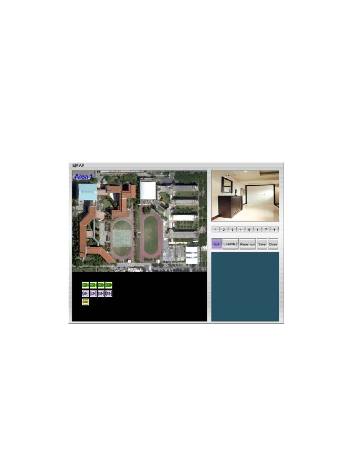
2.2.1 Setting Up and Using the Emap
Emap can hold up to 8 maps in *.jpg format. You may locate the camera, sensor and relay on the map.
2.2.1.1 To Set Up the Emap
1. Click Emap.
2. When the Emap screen appears, click the area number (1 to 8 buttons) on where you want to insert
the map.
3. Click Load Map to insert the map. When the open dialog box appears, locate and select the map and
click Open.
4. When the inserted map appears on the Emap screen, click Edit. You may now drag and drop the
camera, sensor, and relay icons to its place on the map. Icons on the map can be relocated anywhere.
If you are going to relocate the icon on the map to other area, you need to drag the icon to the black
pane at the bottom of the Emap screen and then switch to the area on where you want to locate the
icon. To bring all the icons back to the black pane at the bottom of the Emap screen, click Reset Icon.
5. When you are done, click Save button to save the new setting. To exit Emap screen, click Close.
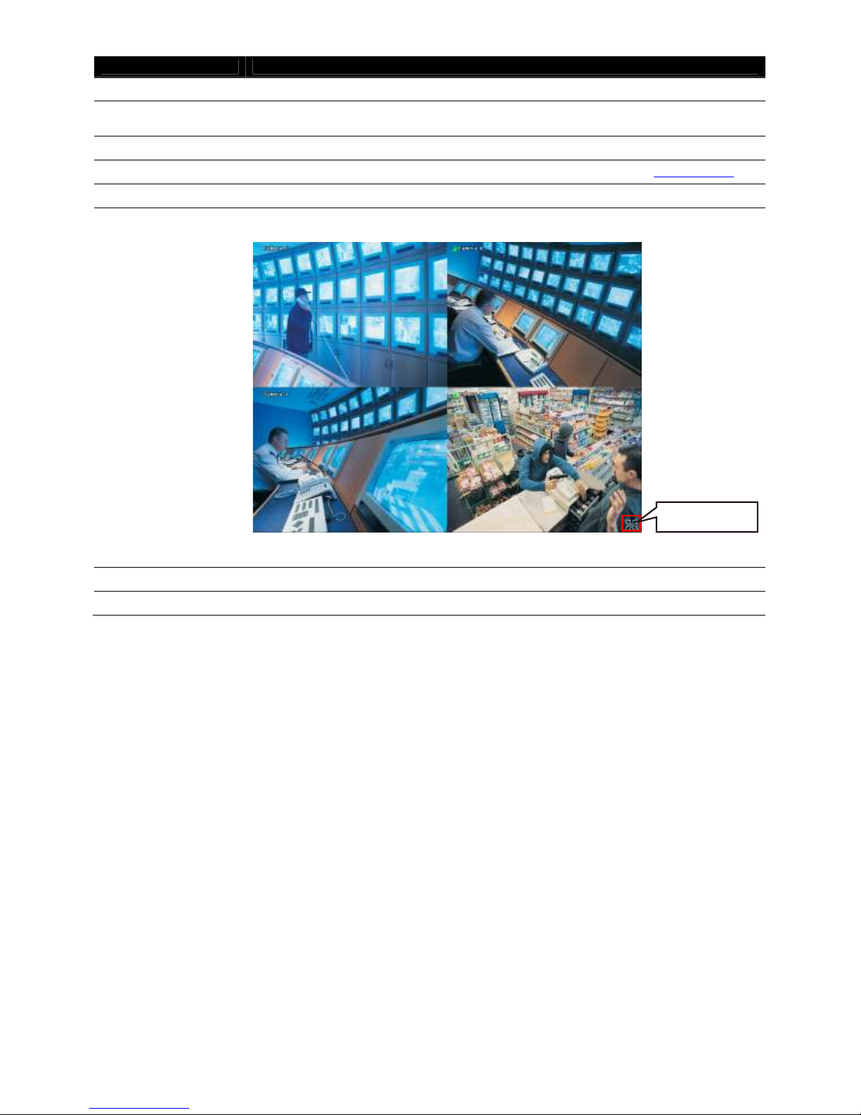
2.2.1.2 To Use the Emap
1. Click Emap.
2. In the Emap screen, click the camera icon to switch on the area where the camera is located on the
map and to display the video at the upper right corner of the Emap screen. At the lower right corner of
the Emap screen, it lists all the warning messages.
3. To view different Emap, click Emap number button (1 ~ 8).
4. Click Close to exit Emap screen.
10
Page 17
1)
(3)
(4)
(5)
(6)
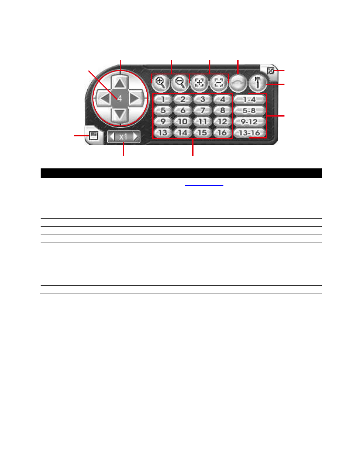
2.2.2 Familiarizing Yourself with the Buttons in PTZ Camera
Controller
(7)
(2)
(1)
(1
(8)
(9) (10)
Name Function
(1) Setup Configure PTZ cameras.(see also Chapter 2.2.2.1)
(2 Close Exit PTZ camera controller.
(3) AutoPan Operate the PTZ cameras automatically based on the selected camera group preset
position number.
(4) Focus +/- Adjust the focus manually to produce clear image.
(5) Zoom +/- Zoom in and out the image.
(6) Direction buttons Adjust and position the focal point of the PTZ camera.
(7) Camera ID pane Display the PTZ camera number that is being operated.
(8) Save Camera
preset position
(9) Camera lens
speed controller
(10) Camera preset
position number
(11) Group AutoPan Select to automatically operate PTZ camera in group.
Save the PTZ camera preset position number. Select the camera and click the preset
position number and save it.
Adjust the moving speed of the PTZ camera lens.
Move the PTZ camera to the preset point.
11
Page 18
2.2.2.1 Setup the IP PTZ Camera
When IP PTZ camera has been successfully connected to the NVR system, user can use the PTZ
function directly without any configuration. To make connection of IP PTZ camera, please refer to Chapter
3.2.1.
In PTZ camera panel, user can setup the preset position of the camera. The number of preset positions is
dependent on the IP PTZ camera that the user has connected. User can refer to the user’s manual of the
IP PTZ camera to find out the number of the preset positions that are supported.
Please follow the below steps to configure the preset position.
1. On Preview User Interface, select the channel that is an IP PTZ camera connection.
2. Click PTZ button from Preview User Interface and PTZ control panel will show up.
3. In the PTZ control panel, using the arrow button to adjust the position of IP PTZ camera.
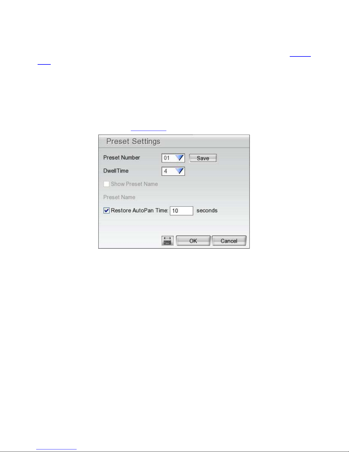
4. And then, click Setup (
see also Chapter 2.2.2). The Preset Settings window will show.
5. Select the Preset Number to assign a number for the PTZ camera current position. And then, click
Save to save the setting.
6. Set the DwellTime for how long the PTZ camera stays in that position before it moves to the next
one.
7. Repeat step 3 to 6, if you want to save another preset position.
8. Restore AutoPan Time: set a time period for restoring auto path function after the PTZ camera has
been moved manually. Mark the check box and set the time period in second.
9. Click OK to complete the setting.
12
Page 19
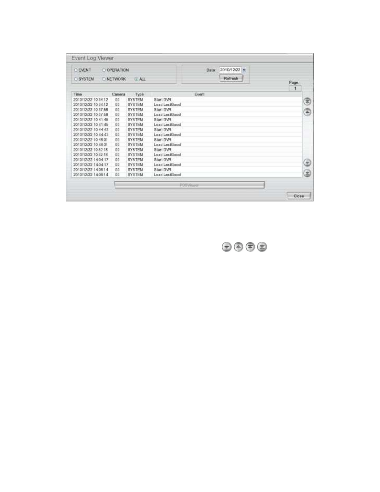
2.2.3 Using Event Log Viewer
Show the record of activities that take place in the system.
1. Click the Event Log button on NVR system main interface. The Event log viewer window will show up.
2. Select the Date to view.
3. To filter the records, select and click the select button to display Event, System, Operation, Network
or All.
4. Use the scroll button to go next, previous, first, or last page ( , , , )of event list.
5. To find event log by keyword, enter keyword in F
ind Text column and click Search.
6. The events list which display on the screen can be saved as text file format. To save the events list,
click Save button.
13
Page 20
i
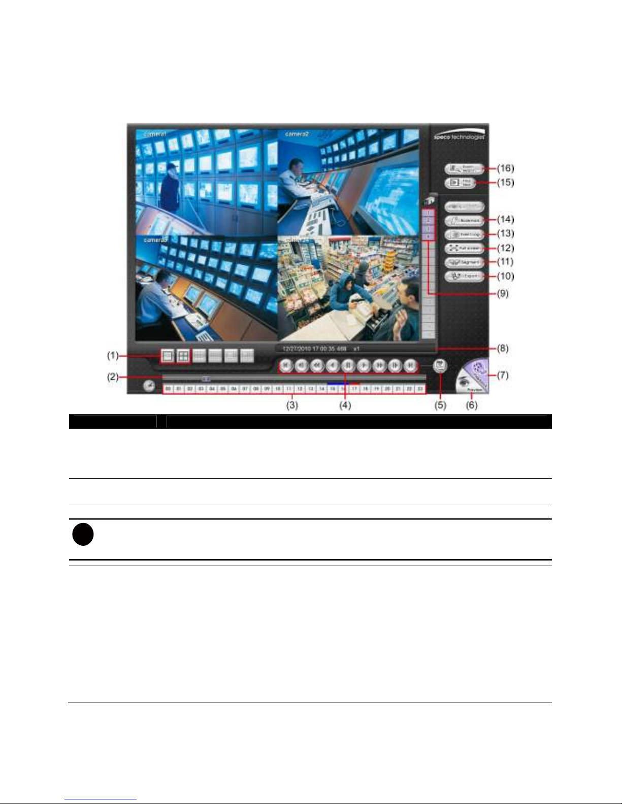
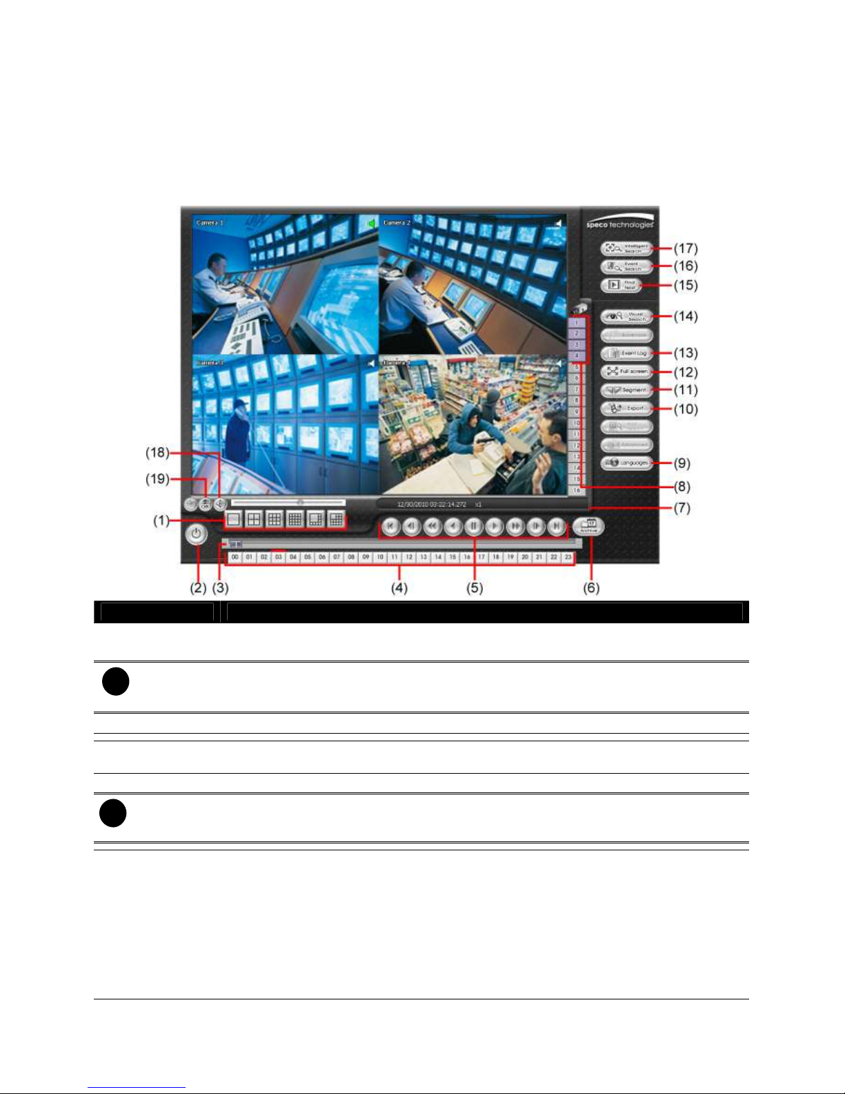
2.3 Familiarizing Yourself with the Buttons in Playback
Mode
To switch in Playback mode, click Playback button at the lower right corner of Preview mode user
interface.
Name Function
(1) Split Screen
Mode
(2) Progress bar Shows the progress of the file being played. You may move the bar to seek at any location
(3) Hour Buttons Select and click to playback the recorded video file on the specific time frame.
The Hour buttons represent the time in 24-hour clock. The blue bar on top of the hour button indicates
that there is a recorded video file on that period of time. While the red bar indicates that you are currently
viewing the recorded video file.
(4) Playback
Control Buttons
Select from 2 different split screen type to playback the recorded video file of all cameras
or one camera on a single screen. When user is in single screen mode, user can
right-click and drag a square on the area to enlarge the view. Right-clicking on the screen
again will return to the normal view.
of the track.
From left to right order:
Begin: Go back to the beginning of the recorded video file.
Previous: Go back to the previous frame.
Slower: Play the recorded video file at the reduce speed from 64x, 32x, 16x, 8x, 4x, 2x,
1x, 1/2x, 1/4x.
Rewind: Wind back the recorded video file.
Pause: Briefly stop playing the recorded video file.
Play: Play the recorded video file.
Faster: Play the recorded video file at the speed of 2x, 4x, 8x, 16x, 32x, or 64x.
Next: Go to the next frame.
End: Go to the end of the recorded video file.
14
Page 21

i
Name Function
(5) Date Select the date on the calendar and the time from 00 to 23 to where to start playing the
recorded video file.
The numbers from 00 to 23 represent the time in 24-hour clock. The numbers from 01 to 04 represent the
camera ID. The blue colored column indicates that there is a recorded video file on that period of time.
While the red colored column indicates on where to start playing the recorded video file.
(6) Preview Switch to Preview mode.
(7) Playback Switch to Playback mode to view the recorded video file.
(8) Status bar Display the recorded date, time and play speed.
(9) Camera ID Show the number of cameras that are being viewed. When you are in single screen mode,
click the camera ID number to switch and view other camera.
(10) Export Export includes Snapshot, Output Video Clip, and Backup function.
Snapshot: Capture and save the screen shot in *.jpg format.
Output Video Clip: Save the segmented file in *.dvr format to external USB storage
device (see also Chapter 2.3.1).
Backup: Save the playback file to external USB device or external DVD burner.
(11) Segment Keep a portion of the recorded video (see also Chapter 2.3.1).
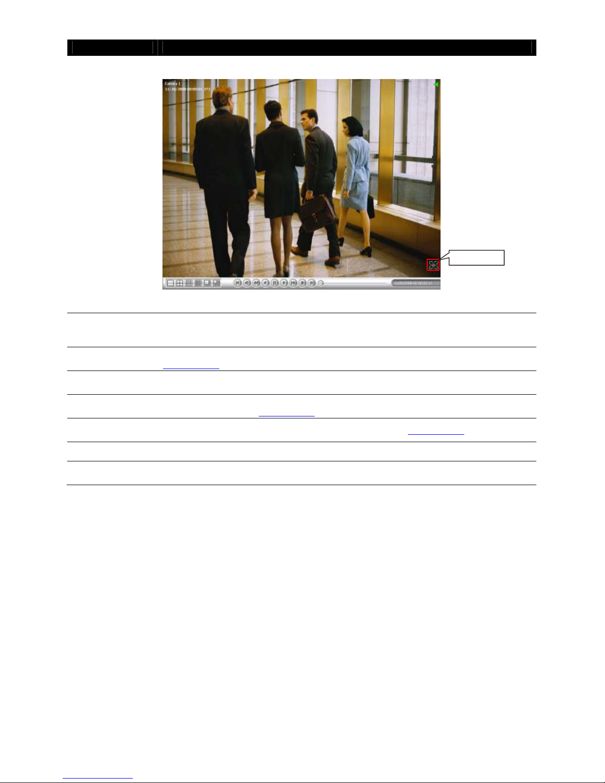
(12) Full screen View in full screen. To return, press the right button of the mouse or ESC on the keyboard
or click the arrow icon.
15
Click to exit from
full screen mode
Page 22
Name Function
When you switch to full screen in multiple-screen mode, Left click to toggle to only display
one of the video in the multiple-screen mode or all.
(13) Event log Show the record of activities that take place in the system. To filter the records, select and
click the option button to only display Event, System, Operation, Network or All.
(14) Bookmark Mark a reference point when reviewing the recorded video file to which you may return for
later reference (see also Chapter 2.3.2).
(15) Find Next Search for the next event or changes in the motion detector frame. You can use this when
you are using Event Search function.
(16) Event Search
Search from the recorded activities that were recorded in event log (i.e., Sensor, Motion,
Video Loss)(see also Chapter 2.3.3)
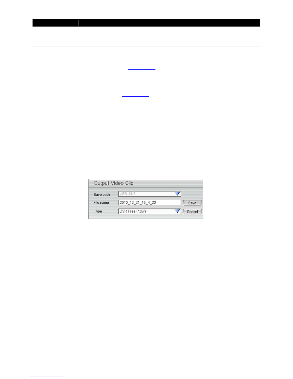
2.3.1 To Segment and Save the Desired Portion of the Recorded
Video
1. Use the Playback Control buttons or drag the bar on the playback progress bar and pause on where
you want to start the segment. Then, click Segment to set the begin mark.
2. Use the Playback Control buttons or drag the bar on the playback progress bar and pause on where
you want to end the segment. Then, click Segment to set the end mark. To cancel segmentation or
set the segment marks from the start, click Segment button again.
3. Click Export > Output Video Clip button to save the wanted portion.
4. In the Output Video Clip dialog box, locate on where user wants to save the file, type the filename,
and select the video format and click Save to save the video segment.
2.3.2 To Bookmark a Video Section
1. Click Bookmark button
2. In the Bookmark dialog box, you may do the following:
- Add to create the new reference mark in the bookmark list. In Bookmark Editor window, enter the
name or a short description in Mark column for this bookmark.
- Edit to change the mark description.
- Delete to remove the selected reference mark in the list.
- Delete All to remove all the reference marks in the list.
- Exit to close Bookmark dialog box.
16
Page 23

3. Select and click one in the bookmark list to review the file.
17
Page 24
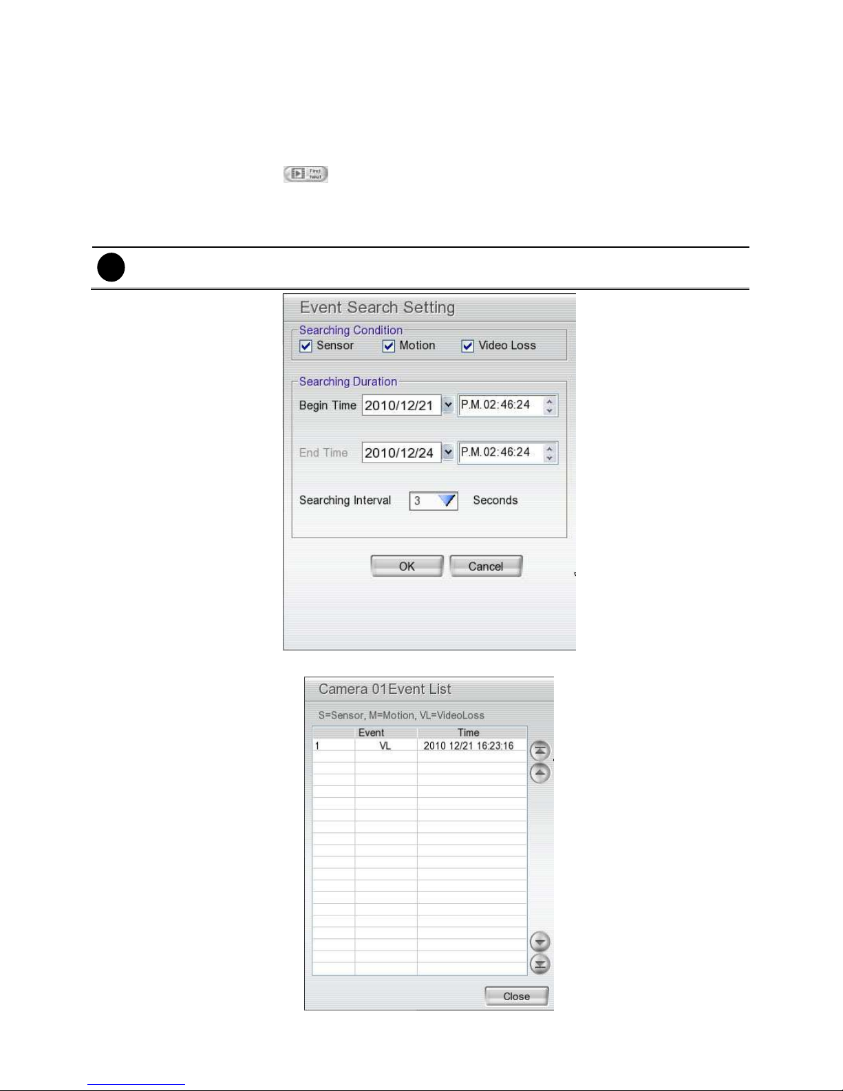
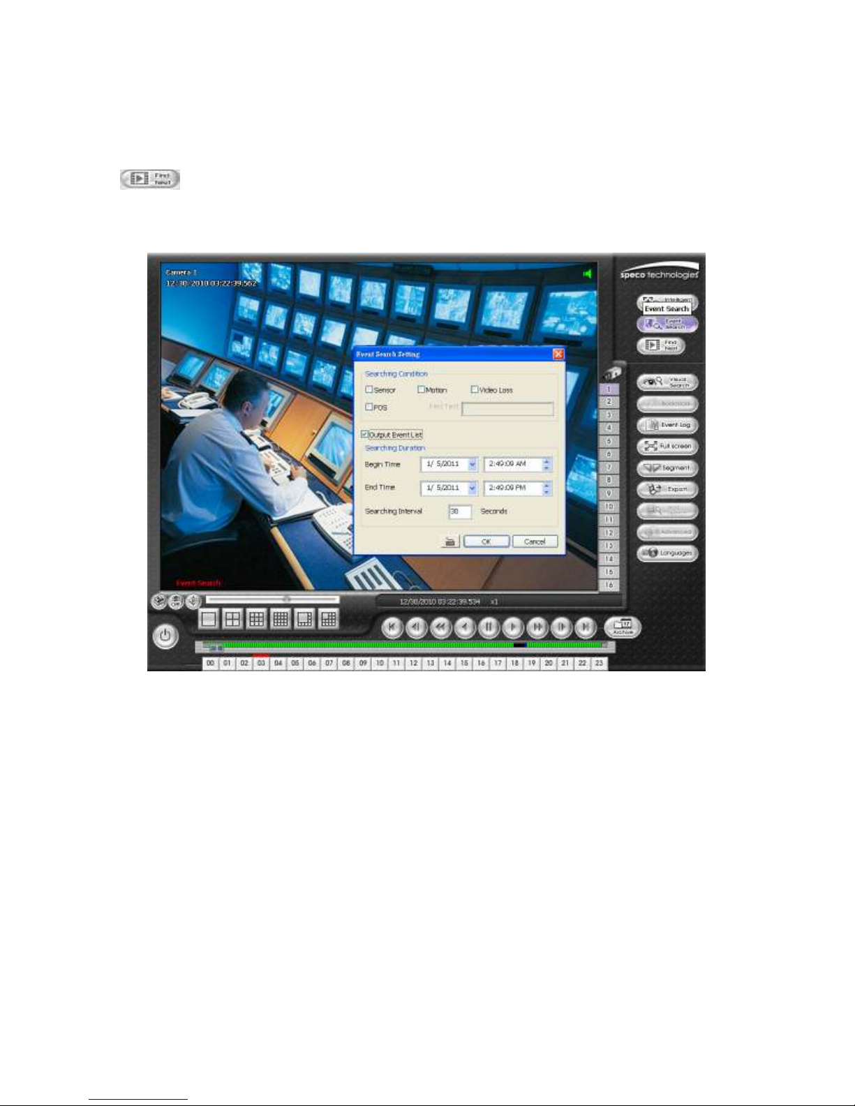
2.3.3 Using the Event Search
1. Click on the video screen on where you want to search.
2. Click Event Search. The Event Search Setting dialog box would appear on the screen.
3. In the Event Search Setting dialog box, check the type of condition you want to search. Then, click
to start searching. The video search would stop at the frame that matches the condition. To keep on
searching click
4. You may also set the search to list all of the search results. Set the Begin Time and End Time. Set
the Searching Interval time to the smallest event time, since if there is more than one event within
the search interval, the event will not be listed. Then, click OK to start searching.
The NVR system will set the date of End Time at 3 days later of Begin Time automatically. If event data
i
are less than 3 days, the NVR system will set End Time at current date. Time of End Time is adjustable.
Find Next
( ) button.
OK
5. When the Event list appear, click and select the item you want to view.
18
Page 25
1)
Chapter 3 Customizing the NVR System
In the Preview screen mode, click button to customize your NVR. Enter the ID and password to
authenticate (Default ID is
When the NVR configuration setup selection appears, select and click on the button of the setting that you
want to change.
admin
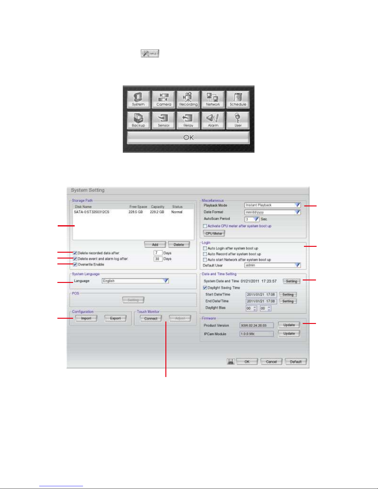
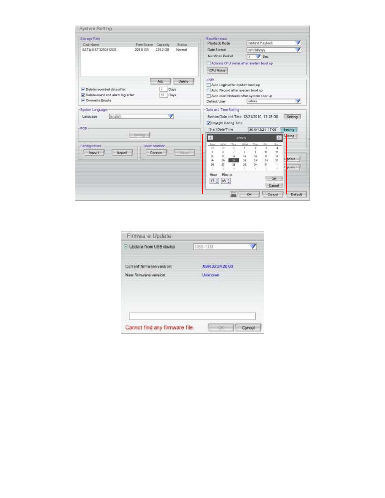
3.1 System Setup
In the System Setting dialog box, click OK to accept the new settings, click Cancel to exit without saving.
and password is
admin
).
(1)
(2)
(3)
(4)
(5)
(6)
(7)
(8)
(9)
(10)
(1
(1) Storage Path
Indicates which HDD the data is being stored on. In case there is more than one storage device, the
system automatically saves the data to the next storage device. To insert another storage device, click
Add and select the storage path. To remove the selected path, click Delete.
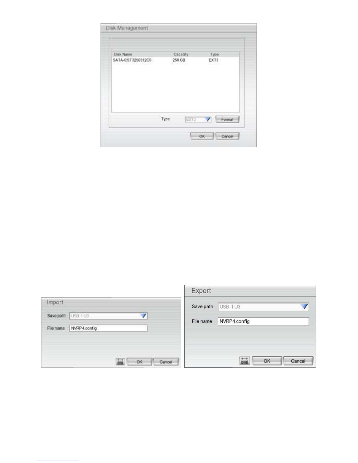
If the hard disk is being used for the first time in the NVR system, please format the hard disk before use.
To format the hard disk, click Add and select the hard disk and Format in Disk Management window, and
then, click Format button.
19
Page 26
(2) Delete recorded data after
If you want the system to automatically erase the data after certain days, enable the Delete recorded
data after check box and enter the number of days in Days text box.
(3) Delete event and alarm log after
If you want the system to automatically erase the event and alarm log after certain days, enable the
Delete event and alarm log after check box and enter the number of days in Days text box.
(4) Overwrite Enable
When the recording space is not enough to record one hour of data, the system will automatically replace
the oldest data with the newest recorded data.
(5) Language
Customize the system to display the tool tips and dialogs based on the selected language. Default
language is English.
(6) Configuration
Exports a copy of all the configuration settings and allows you to reload the same settings from a USB
drive. To save the current settings, click Export. To replace the current settings with the stored settings on
the USB drive, click Import.
Import User Interface Export User Interface
20
Page 27
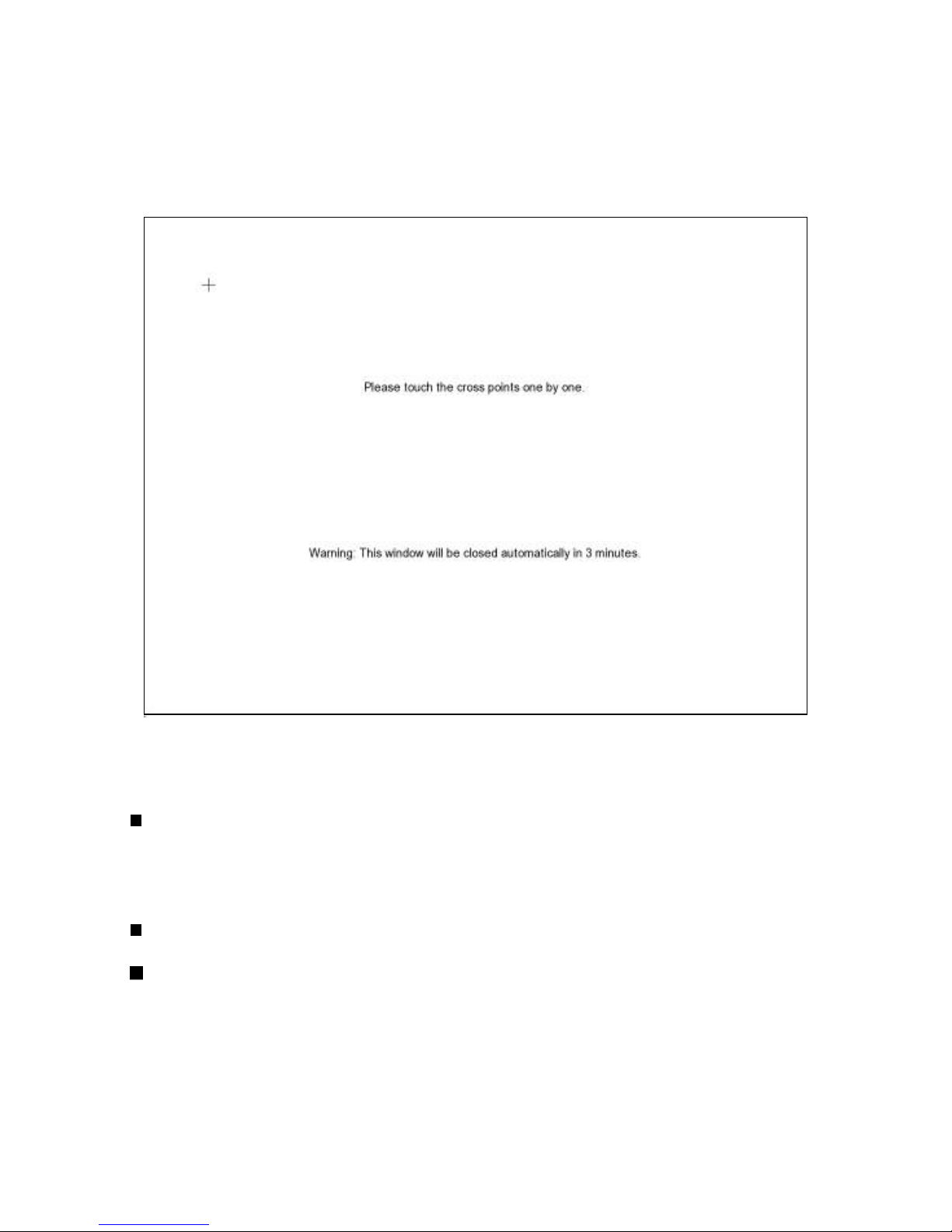
(7) Touch Monitor
When NVR server is connected to a touch monitor, user needs to configure the touch monitor to
communicate with the NVR.
1. Connect the touch monitor with NVR server.
2. Turn on the NVR server and touch monitor power.
3. Select Setup → System → Touch Monitor → Adjust.
4. The adjusting window will show up.
5. Click + one by one to complete the adjustment.
6. To disconnect touch monitor, click Disconnect button first, and then turn off the touch monitor and
remove the connection between NVR server and touch monitor.
(8) Miscellaneous
Playback mode: Select the mode of playback video.
– Select date and time: Playback the recorded video beginning from the selected date and
time.
– Play the last file: Automaticallyy playback the recorded video from the last hour
– Instant Playback: Automatically playback the video which has just recorded
Date Format
Select the date format which wants to display in select date and time playback mode
Auto Scan Period
Set the time gap of the Auto Scan function from 3 to 10 seconds. This automatically switches to
the next video in cycle depending on the set time gap.
(9) Login
Enable the conditions in Login section you want the system to automatically carry out.
- Auto Login after system boot up
Automatically logs in the user when NVR is powered up.
- Auto Record after system boot up
Automatically starts video recording when NVR is powered up.
21
Page 28

- Auto start Network after system boot up
Automatically starts network connection when NVR is powered up.
- Default user
Automatically log in to the selected default user when NVR is powered up.
(10) Date and Time Setting
System Date and Time: Adjust the NVR system time and date. Click Setting button to select the
month, date, hour, and minute.
Daylight Saving: Check Daylight saving check box to enable daylight saving function. Then, select
the Start Date/Time and End Date/Time by clicking on the Setting button.
Daylight Bias: Select the daylight saving time offset for your time zone. For example: if the time
zone is in U.S. Eastern, the time offset is 1 hour.
22
Page 29
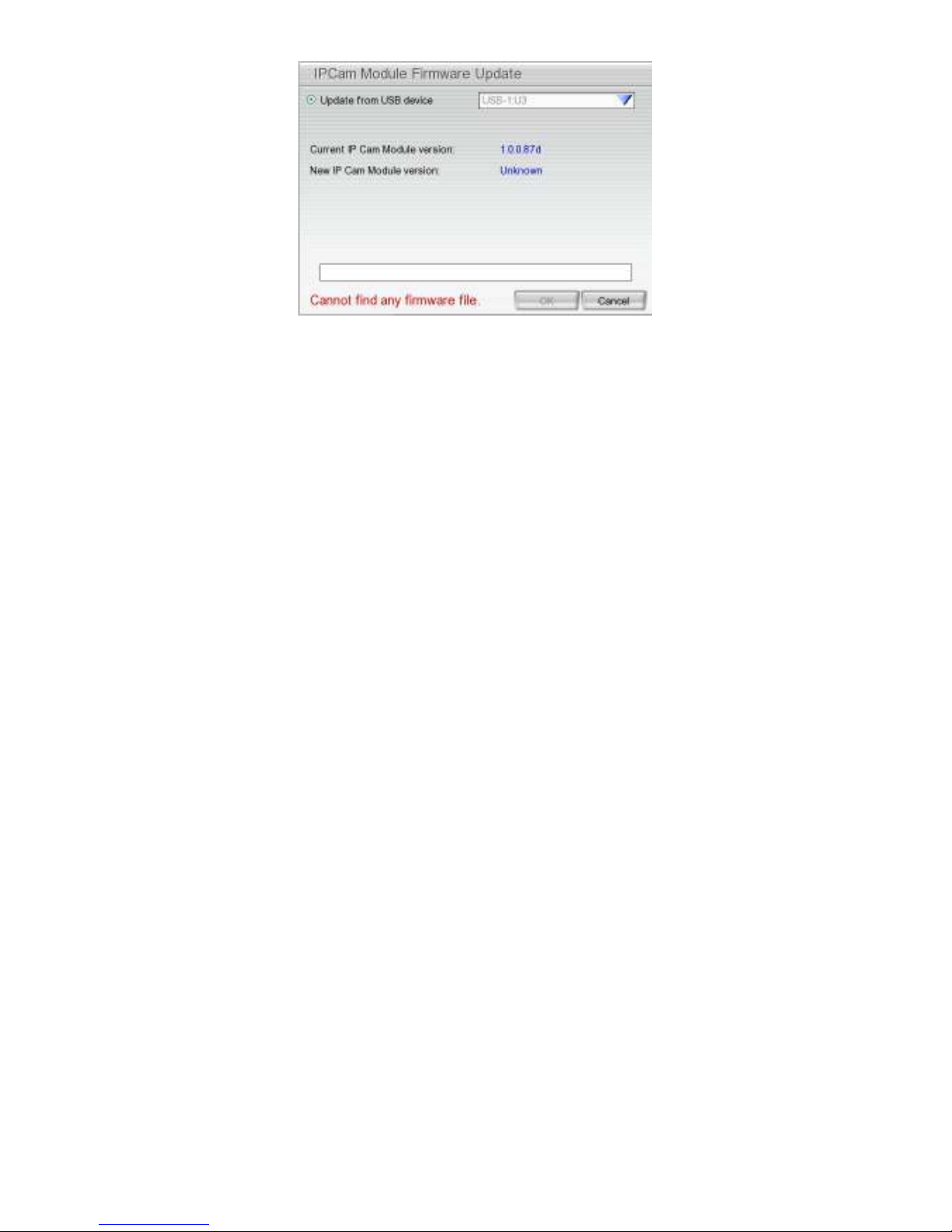
(11) Firmware
Product Version Update: Upgrades the firmware of NVR system.
1. Click Update button, a Firmware Update window will show up.
2. Save the firmware in the root directory of the USB drive. Insert USB drive into NVR unit.
3. Select the USB drive if there is more than one USB drive from the drop down list. The NVR
unit will auto detect the firmware. The current firmware version will show in Current firmware
version and the new firmware version will show in new firmware version.
4. Click OK to start upgrading.
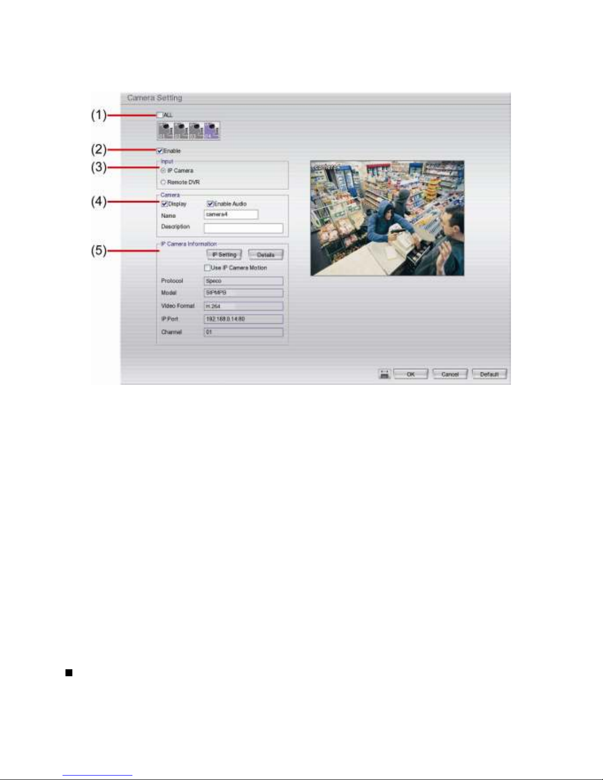
IPCam Module Update: Upgrades the firmware of the IP camera.
1. Click Update button, an IPCam Module Firmware Update window will show up.
23
Page 30
2. Save the firmware in the root directory of the USB drive. Insert USB drive into NVR unit.
3. Select the USB drive if there is more than one USB drive from drop down list. The NVR unit
will auto detect the firmware. The current firmware version will show in Current IP Cam
Module version and the new firmware version will show in New IP Cam Module version.
4. Click OK to start upgrading.
24
Page 31
3.2 Camera Setup
3.2.1 To Setup the IP Camera
(1) Camera Icons
Select the camera number you want to view. To enable/disable all cameras, click ALL check box.
(2) Enable
Set to enable/disable the selected camera. Disable when there is no video source on the camera channel
so that the NVR does not detect video loss error on the channel.
(3) Input
Select the camera type as IP Camera.
(4) Camera
- Display
Enable/disable to show the video. Even if the video of the selected camera is hidden you can still
record the video and preview it in playback mode.
- Enable Audio
Enable/disable audio of the camera.
- Name
Change the camera name
- Description
Add a short comment
(5) IP Camera Information
- Use IP Camera Motion: Check to enable the motion detection function of the IP camera if it is
supported. To setup IP camera and display current IP camera information.
IP Setting: Click IP setting to add the IP camera.
25
Page 32

i
1. Click the radio button of Protocol to setup IP camera.
2. Select the Protocol, Model, Video Format, and Channel of the IP camera.
3. Enter IP address and connecting port in IP Camera Site column.
4. Also, user can enter URL of IP camera instead of IP address.
5. If the IP camera has authentication request, please enable Authentication and enter ID and
Password.
6. Click OK to connect with the IP camera.
Detail: To adjust IP camera parameters, click Detail.
Click on Default to revert to the factory default values.
User can select Video size, Frame rate, Bitrate mode and Quality of camera. User can also adjust
Bright, Contrast, Hue, Saturation, and I/O Control of the camera.
The selection and adjustment items may vary by the camera supported.
26
Page 33

I/O Control: Setup the sensor and relay that is built into the IP camera.
Sensor Setting
1. Click Sensor button.
2. Click the drop-down list and select the sensor ID number.
3. Enter sensor name in Name column
4. The system automatically detects the camera and input relates information. In the Content
section, enter sensor Description.
5. In the test section, click Test to check the sensor status. Red is high and Green is low.
6. Click OK to exit and accept the setting or Cancel to exit without saving the setting.
27
Page 34

Relay Setting
1. Click Relay button.
2. Click the drop-down list and select the relay ID number.
3. Enter relay name in Name column
4. The system automatically detects the camera and enters related information. In the Content
section, enter relay Description.
5. In the test section, click Test to check the relay status. Red is high and Green is low.
6. Click OK to exit and accept the setting or Cancel to exit without saving the setting.
28
Page 35

3.2.2 To Setup Camera from the Remote DVR
User can add the camera from another DVR through the network.
(1) Camera Icons
Select the camera number you want to view. To enable/disable all cameras, click ALL check box.
(2) Enable
Set to enable/disable the selected camera. Disable when there is no video source on the camera channel
so that the NVR does not detect video loss error on the channel.
(3) Input
Select the camera type as Remote DVR.
(4) Camera
- Display
Enable/disable to show the video. Even if the video of the selected camera is hidden you can still
record the video and preview it in playback mode.
- Enable Audio
Enable/disable audio of the camera.
- Name
Change the camera name
- Description
Add a short comment
- IP
Enter the IP address of the camera
- Port
Enter the connection port of the camera
- User ID
Enter the user id for authentication
- Password
29
Page 36

Enter the password for authentication
- Channel
Select the channel of connected camera
- Connect
Click to connect the camera when all configurations are set.
3.3 Recording Setup
(1) Camera Icons
Select the camera number you want to set the recording setting. To select all the cameras, enable the
ALL check box. To select more than one camera, Right click on the camera icon. To select one camera
only, Left click on the camera icon. The camera icon turns purple when it is selected.
(2) Recording Mode
The horizontal blocks from 00 to 23 represent the time in 24-hour clock and the vertical block 1 to 7
represent the day in the week block (Sunday to Saturday). To record in full 24 hours and 7 days a week,
select the recording mode and click the button. If you want to only record at a particular time or day,
click Schedule button and select the Recording Mode , and then click on the time or day blocks.
When the system starts recording a red triangle mark would appear at the upper left corner of the screen.
The recording modes are listed below:
30
Page 37

- Always Recording
Always record the video from the selected camera and save it to the designated storage device
- Motion Recording
Records the video from the selected camera when motion is detected by the system. Once motion
is detected, the system automatically saves the previous frames and stop based on the Start
Record Prior and Stop Record After settings.
- Smart Recording
Automatically switch to record at the maximum frame rate once motion is detected, and switch to
record at minimum frame rate when no motion is detected.
- No Recording
The system does not record.
(3) Motion Detection
Adjust the sensitivity of the motion detection. The higher the sensitivity, the finer motions are detected.
hen motion is detected, a green triangle mark would appear at the upper left corner of the screen.
W
31
Page 38

3.4 Network Setup
Click on Default to revert to the factory default values.
(1) Server Name
Assign a name for the NVR unit. Alphabetical and numerical letters only.
(2) Transmitting Cameras
Select and click on the camera number in the Transmitting Camera section to enable each camera to be
accessible via internet using WebViewer, Remote Console, CM3000(Gold),PDA Viewer and JavaViewer
(still image). To select all the cameras, enable the ALL check box.
(3) Main Configuration
Set the NVR IP address and Remote Console Port. This is required for accessing NVR server from a
remote location via internet.
The NVR system supports dual LANs; user can select the Server IP from the drop-down list and click
Setting to configure the details. The dual LAN ports balance network bandwidth to avoid network traffic
congestion.
- The default IP of the NVR server is 192.168.2.2 for LAN1 (lower LAN port in the back of the NVR) and
i
192.168.3.2 for LAN2 (upper LAN port in the back of the NVR).
- LAN1 can be set as Static or DHCP mode and supports only for LAN connection.
- LAN2 can be set as Static, DHCP, or PPOE mode and supports both WAN and LAN connections.
- Both LAN ports cannot be configured in the same LAN segment; this will cause network connection
failure.
- When only using port LAN2, please set IP address of port LAN1 in different LAN segment from port
LAN2.
32
Page 39

Using the following IP address:
parameters in
-
Assign a static IP address to the NVR system.
IP:
-
Mask:
-
Gateway:
User only can setup one gateway for the NVR system. LAN2 is recommended for setting the gateway data
i
because LAN2 has access to the internet.
IP information
Assign the subnet mask of the IP address of the NVR system.
Enter the network gateway IP address
Assigns an IP address for the NVR system. Fill in the IP related
section.
-
-
Obtain an IP automatically (DHCP):
PPPOE:
Ethernet frames. It is used mainly with ADSL services. If your network is using ADSL service
connecting to internet, and then, select PPPOE mode. Enter
your ISP for PPPOE connection authority.
DDNS:
for translating domain names into Internet addresses. Users can register their own domain name on
http://speco.dss.com.tw
-
-
-
-
(4) Remote Upgrade Configuration
Enter the port number that is used for remote firmware upgrade through the network.
(5) WebViewer Configuration
Activate Enable Anonymous Login to remotely access the NVR server without authentication. Fill in the
WebViewer PORT for remote access connection through the network.
(6) Network Time Synchronization
Synchronizes the NVR system time to the network time server. Fill in the Time Server IP address or
domain name and select the Time Zone. User can enable Automatic Synchronize at to set automatic
synchronization on a daily basis. Or, user can click Synchronize Time Right Now to synchronize time
Domain Name Server translates domain names (such as www.specotech.com) to IP
DNS:
addresses. Enter the IP address of DNS if it is available.
MAC Address:
for identification. Auto filled by the NVR system.
Point-to-Point Protocol over Ethernet is a network protocol for encapsulating PPP frames in
DDNS (Dynamic Domain Name Service) is a data query service mainly used on the Internet
Domain Name
Enter the domain name that the user had registered.
Password
The password used to access DDNS when the domain name was registered.
DDNS Server Name
Select your DDNS server. By default, there is only one DDNS server. May provide more DDNS
servers in future.
DDNS Server Port
Fill in the port that connects to DDNS server. Default is 1053.
An identifier hardware address of NVR unit that is assigned by the manufacturer
Assign the IP address by local DHCP server to NVR system.
. (See Appendix A
User ID
)
and
Password
that is given by
33
Page 40

right away.
(7) Other Configuration
- Enable White List
An access permit list for the remote accessing of NVR server. Enter the IP address and click Add.
Or, enter a range of IP address and click Add. To delete the IP from the list, select the IP and click
Delete button. To reset the input, click Clear button.
- Network Bandwidth Limit
By Channel: Set the network bandwidth consumption limit by each channel.
All: Set the total network bandwidth consumption limit.
34
Page 41

3.5 Schedule Setting
Set schedule to record, enable network, reboot and disable alarm of all cameras either weekly or once.
The number from 00 to 23 represent the time in 24-hour clock. The left most column display the days in a
week.
To Set the Schedule Setting:
1. Select the date in the calendar. Use and buttons to shift the calendar to the left or right.
2. Select the condition you want to schedule in the drop down list.
- Record
Activate all the cameras to start video recording at the set time based on the Recording setting
- Enable Network
Activate NVR remote system to access at the set time. After the appointed time, the Network
function will be disabled. If the Network function is already enabled, the Network function will not be
disabled when the appointed time has ended.
- Reboot
Restart the PC at the appointed time.
- Disable Alarm
Deactivate the alarm at the set time temporarily.
3. Set the schedule as weekly or one time. Click to make a selection.
4. Click on the blocks to set the schedule or click All to select all. To un-select the specific schedule
blocks, click the Remove and click blocks to un-select. To store the setting, click Save. To remove the
settings, click Clear.
5. To end Schedule Setting, click OK to exit and accept the setting or Cancel to exit without saving the
setting.
35
Page 42
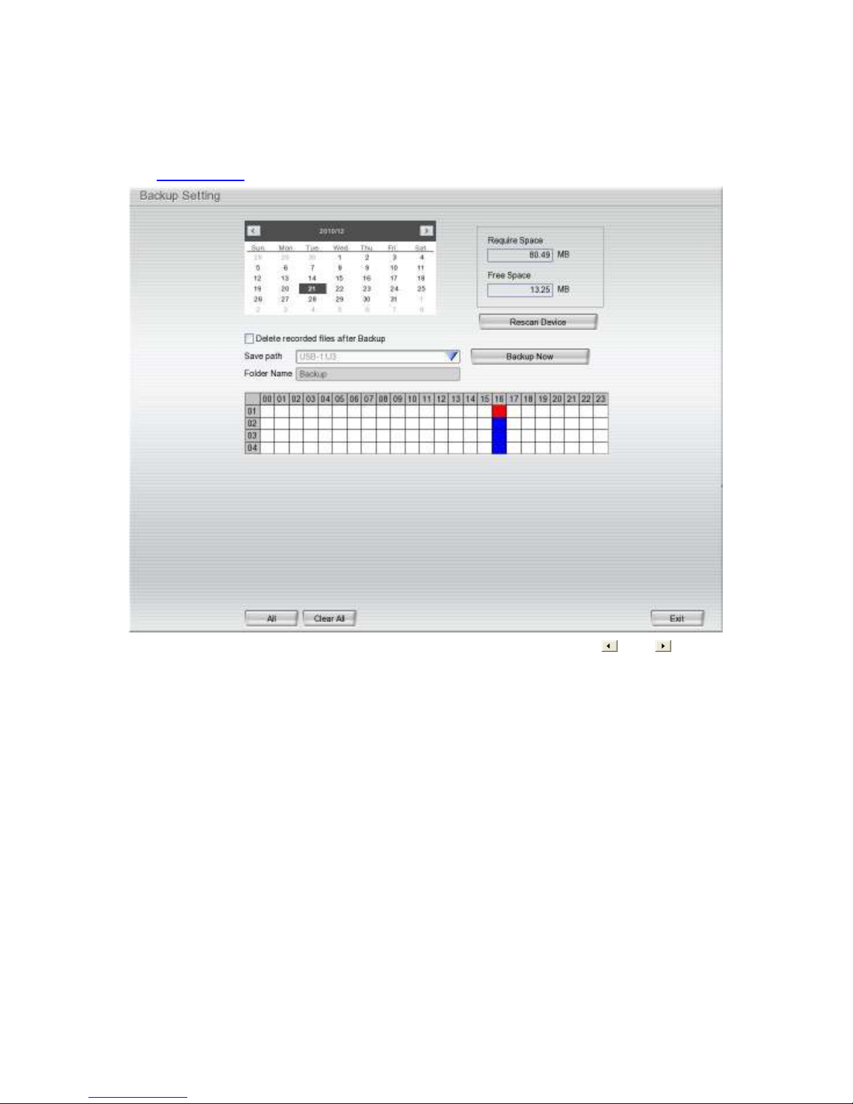
3.6 Backup Setup
In the Backup Setting dialog box, the number from 00 to 23 represent the time in 24-hour clock. The
numbers from 01 to 04 represent the camera number. When you back up the file, you may find Qplayer
application included in the backup folder. To run the Qplayer application, click Qplayer.exe in back folder.
(See also Chapter 3.7.1)
1. Select the date of the recorded file in the calendar you want to backup. Use and buttons to
shift the calendar to the left or right.
2. The block in blue indicates there is recorded data. In the table above, click on the blue block to select
the recorded file or click camera (01~04) or time (00~23) to select the whole row or column. The blue
block turns red when it is selected. If you want to set the specific time, right-click on the selected block.
Then, set the start time and end time.
3. Check the space needed for backup next to the calendar. Click Rescan Device to calculate the space
for backup.
– Require Space: Shows the total size of the backup file.
– Free Space: Shows the available storage space.
4. If you do
check box.
5. Select the backup device – USB drive or DVD-ROM device.
6. NVR system will enter
7. Click
Backup Now
want to keep the recorded file in the archive folder, enable
NOT
Folder Name
button to start archiving the selected file.
automatically.
Delete files after Backup
36
Page 43
3.6.1 Using QPlayer to Playback Backup Video
You can playback the backup files using QPlayer application on the PC. When you back up the recorded
file, the QPlayer application is automatically included in the backup folder. With QPlayer, the mode is the
same as in Playback mode and supports different split screen types to view all the video at the same time.
However, that there are no Preview and Playback buttons.
To run the application, go to backup folder and double-click Qplayer .exe to run the QPlayer.
Name Function
(1) Split Screen
Mode
- If there are only 4 cameras, when user selects the 8, 9, 13, and 16-spilt screen mode, only 4 channels
i
(2) Exit
(3) Progress bar Shows the progress of the file being played. You may move the bar to seek at any location
(4) Hour Buttons Select and click to playback the recorded video file on the specific time frame.
i
(5) Playback
Control Buttons
have video display and rest of channels will be black screen.
- To zoom in an area on the screen, Right click and Drag a square on the area you want to enlarge.
The Hour buttons represent the time in 24-hour clock. The blue bar on top of the hour button indicates
that there is a recorded video file on that period of time. While the red bar indicates that you are currently
viewing the recorded video file.
Select from 1 and 4-split screen type to playback the recorded video file.
Close the application
of the track.
Begin: Move at the beginning of the recorded video file.
Previous: Go back to the previous frame.
Slower: Play the recorded video file at the speed of 1/2X, 1/4X, 1/8X, 1/16X, or 1/32X.
Rewind: Wind back the recorded video file.
Pause: Briefly stop playing the recorded video file.
Play: Play the recorded video file.
Faster: Play the recorded video file at the speed of 2x, 4x, 8x, 16x, or 32x.
Next: Go to the next frame.
End: Go to the end of the recorded video file.
37
Page 44

Name Function
(6) Archive Select the date on the calendar and the time from 00 to 23 to indicate where to start
playing the recorded video file.
– Day Light Saving: the playback calendar will show the available video records during
day light saving time period.
– OPEN FILE: user can open the recorded file from other storage location on hard disk.
– Channel 01~16/Channel 17~32: Click it to switch between channel group 01~16 and
channel 17~32 on calendar if NVR server supports more than 16 channels.
The numbers from 00 to 23 represent the time in 24-hour clock. The numbers from 01 to 04 represent the
i
camera ID. The blue colored column indicates that there is a recorded video file on that period of time.
While the red colored column indicates where to start playing the recorded video file.
(7) Status bar Display the status of the recorded date, time and play speed.
(8) Camera ID Shows the number of cameras that are being viewed. When you are in single screen
mode, click on the camera ID number to switch and view other cameras.
(9) Languages Customize the system to display the tool tips and dialogs based on the selected language.
By default the language is in English.
(10) Export Export includes Snapshot, Print, and Output Video Clip function.
Snapshot: Captures and saves the screen shot in *.jpg format.
Print: Prints the screen shot.
Output Video Clip: Saves the segmented file in *.dvr, *.avi, or *.mpg format.
(11) Segment Keep a portion of the recorded video (see also Chapter 3.6.2).
38
Page 45
Name Function
(12) Full screen View in full screen mode. To return, press the right button of the mouse or ESC on the
keyboard or click the arrow icon.
Click to exit from
full screen mode
When you switch to full screen in multiple-screen mode, Left click to toggle to only display
one of the video in the multiple-screen mode or all.
(13) Event Log During backup, the NVR system will also include event logs. User can view the event log
of activities that took place in the system. To filter these records, select and click the option
button to only display Event, System, Operation, Network or POS.
(14) Visual Search Search from a specific camera by Date, Hour, Minute, 10 Seconds and Second. (See also
Chapter 3.6.3)
(15) Find Next Search for the next event or changes in the motion detector frame. You can use this when
you are using Intelligent Search or Event Search function.
(16) Event Search Search from the recorded activities that were recorded in event log (i.e., Sensor, Motion,
)
(17) Intelligent
Search
(18) Audio
Video Loss). (See also Chapter 3.6.4
Search the changes in the motion detector frame (See also Chapter 3.6.5).
Enable/disable volume
(19) De-interlace To enhance the video quality, set the de-interlace mode to #1 if you are capturing
motionless picture, and #2 if capturing lots of movement.
39
Page 46
3.6.2 To Cut and Save the Portion of the Recorded Video
1. Use the Playback Control buttons or drag the bar on the playback progress bar and pause to select
the beginning of the segment. Then, click Segment to set the begin mark.
2. Use the Playback Control buttons or drag the bar on the playback progress bar and pause to select
the end of the segment. Then, click Segment to segment. To cancel segmentation, click Segment
button again.
3. Click Export > Output Video Clip button to save the segmented portion.
4. In the Save As dialog box, locate on where you want to save the file, type the filename, and select
the video format.
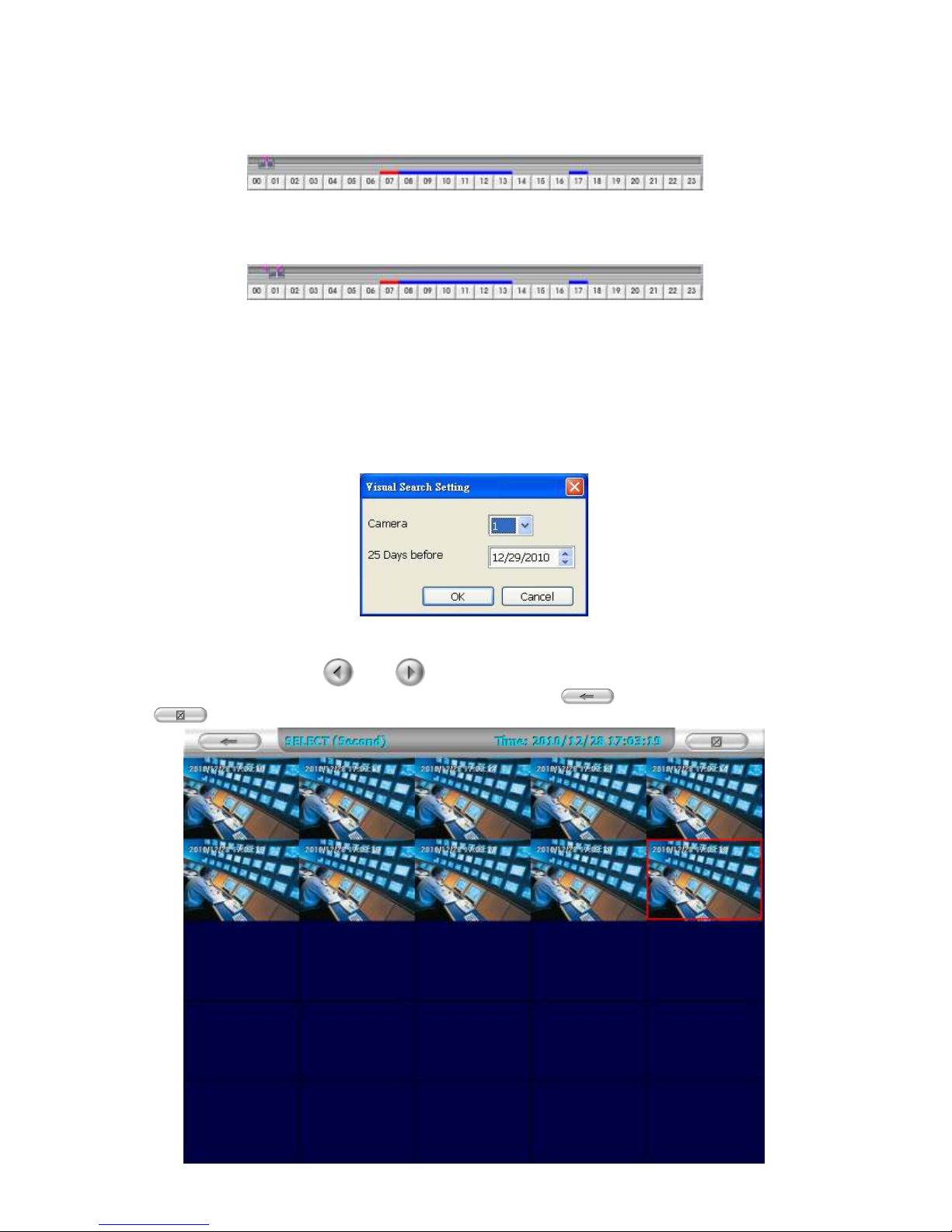
3.6.3 Using the Visual Search
1. Click Visual Search.
2. In the Visual Search Setting dialog box, select the Camera number and the date. Then click OK.
3. When a series of frames appear by date, click on the frame to display another series of frames and
search by every Hour of that date, every Minute of that hour, 10 Seconds, 3 Seconds, and every
Second of that minute. Use
back to the last time selected (hour, minute, or second), click . To close event search,
click .
and to go to the next and last page of the time page. To go
40
Page 47
3.6.4 To Search Using the Event Search
1. Click on the video screen on where you want to search.
2. Click Event Search. The Event Search text (red) would appear at the lower left corner of the screen.
3. In the Event Search Setting dialog box, check the type of condition you want to search. The video
search would stop at the frame that matches the condition. To keep on searching click
( ).
4. You may also set to search and list all the result. In the Search Duration section, set the Begin Time
and End Time. Set the Searching Interval time to the smallest event time, since if there is more than
one event within the search interval, the event will not be listed. Then, click OK to start searching.
Find Next
5. When the Event list appear, click and select the item you want to view.
41
Page 48

3.6.5 To Search Using the Intelligent Search
1. Click on the video screen on where you want to search.
2. Click Intelligent Search. The Intelligent Search text (red) would appear at the lower left corner of the
screen.
When the Intelligent Search Setting dialog box and motion detector frame appear, you may adjust the
3.
sensitivity bar and the motion detector frame size and location. To set motion detector frame size and
location, left click and drag on the screen. Then, click OK to start searching. The video search would
stop at the frame that matches the condition. To keep on searching click
may also set to search and list all the result. Check the
the
Begin Time
there is more than one event within the search interval, the event will not be listed. Then, click
start searching.
and
End Time
. Set the
Searching Interval
box. In the
List
time to the smallest event time, since if
Find Next
Search Duration
(
). You
section, set
to
OK
42
Page 49

3.7 Sensor Setting
The I/O device must be installed to use this function.
1. The system automatically detects the I/O device that is connected to the NVR system and is displayed
on the drop-down list column. Click the drop-down list and select the sensor that the user wants to
configure.
2. Enter sensor name in Name column.
3. In the Content section, enter Description of sensor.
4. In the test section, click Test to check the sensor status. Red is high and Green is low.
5. Click OK to exit and accept the setting or Cancel to exit without saving the setting.
43
Page 50

3.8 Relay Setting
The I/O device must be installed to use this function.
1. The system automatically detects the I/O device that is connected to the NVR system and is displayed
on the drop-down list column.
2. Enter relay name in Name column.
3. In the Content section, enter Description of relay.
4. In the test section, click Test to trigger relay. Red is high and Green is low.
5. Click O
K to exit and accept the setting or Cancel to exit without saving the setting.
44
Page 51

3.9 Alarm Setting
In the Alarm Setting dialog box, click Add to insert and set new alarm setting, click Delete to remove
the selected alarm setting, click OK to exit and save the setting, Cancel to exit without saving. Click
on Default to revert to the factory default values.
1. Click Add to insert and set a new alarm setting. Click the items in the (8) Alarm Setting List if you
want to modify the alarm setting.
2. In (1) No./Name/Description enter alarm name and description. Alarm No. will be created by NVR
system.
3. In (2) Enable Time, the number from 00 to 23 represents the time in 24-hour clock. Select the time and
click the block you want to activate or deactivate the alarm function. When it is deactivated the color of
the block turns white.
4. In (3) Conditions, you can set “Trigger if any” to activate if it falls under one of the conditions or
“Trigger if all” to activate if it falls under all conditions.
5. In (4) Camera section, select and click on the camera number (01 to 04) in Motion Detected and
Video Loss to set the condition for the system to trigger alarm.
6. In (5) Sensor, select and click on the sensor number to set the condition for the system to trigger
alarm. If the sensor status is normally high, set the sensor condition to low.
- IP Camera Sensor: To adjust sensor output of the IP camera to high/low.
- Enable/disable the Abnormal Event check box, to set the condition of the event for system to
trigger alarm.
45
Page 52

Reboot: when the NVR system reboots without an abnormal condition, the system will send
out the alarm message.
Abnormal Reboot: when the NVR system reboot under an abnormal condition, the system
will send out the alarm message.
Recording is switched off: when the recording has been stopped, the system will send out
the alarm message.
Network is switched off: when the network connection of NVR system is lost, the system
will send out the alarm message.
Hard Disk failed: when the hard disk does not work normally, the system will send out the
alarm message.
- Continue trigger duration: Set up the trigger duration time. If the sensor is triggered and stays
triggered for this period of time, the alarm will be sent.
7. In (6) Alarm Reset, click the camera number to reset the condition of the alarm. Once alarm is reset,
all alarm action will stop at the moment. If the sensor’s status is normally high, the alarm will reset to
low.
8. In (7) Action, set the alarm action for the system to perform when the alarm condition is activated.
- Launch Emap: Display mini Emap screen.
- Enlarge Camera View
Switch to only display video in Preview mode from where the alarm is activated.
a. Select the camera from drop down list to specify which camera video to be enlarged on the
screen when the alarm is triggered.
b. Retrieve time: set the time duration before system switches back to original Preview mode. If
the retrieve time is un-checked, the alarm video will stay enlarged until user switches back to
Preview mode manually. The retrieve time range is 0~ 600 seconds.
46
Page 53

(1)
(2)
- Relay Output
Enable/disable the relay operation when the alarm is
activated and to extend the duration of the relay output
time.
1. Next to the Relay Output check box, click Detail.
2. In the Alarm Relay dialog box, select from the
available relay list and in the ON column, set to
enable/disable the relay operation when the alarm is
activated.
3. In the Retrieve time check box, you may
enable/disable to extend the duration of the relay
output and set the duration in second.
4. Click OK to exit and accept the setting or Cancel to
exit without saving the setting.
- IP Camera Relay
Set to enable/disable the relay operation when the alarm is activated.
- Play Warning Sound
Play alarm sound.
- Send E-mail
Send an electronic message. Next to the Send Email check box, click Detail.
In the E-mail Setting dialog box, click OK to exit and save the setting or Cancel to exit without
saving the setting.
(1) Mail Server
Enter the SMTP Server and port. If your e-mail system requires user identification, enable
Authentication check box and enter ID and Password.
(2) Mail
Fill the mailing information.
From: Enter the sender e-mail address.
To and CC: Enter the recipient email address and separate it with comma or a semicolon (;).
Subject: Enter the message title.
Message: Type the message.
47
Page 54

- Start Recording
Record the video from the selected camera.
1. Next to the Start Recording check box, click
Detail.
2. In the Alarm Recording Setting dialog box,
select the camera to enable/disable video
recording. Enable All to select all cameras.
3. In the Frame Rate selection, select As Setting
to record the number of frames based on the
Recording Setting.
4. In the Start Record prior text box, check and
set the time in seconds for the program to
begin recording before the alarm is triggered.
The time range is 1~10 seconds.
5. In the S
continue recording after the alarm condition has ended. The time range is 1~999 seconds. If
Stop Record after is not checked, the alarm recording will continue to record until alarm is reset.
6. Click OK to accept the new settings or Cancel to exit without saving.
top Record after text box, check and set the time in seconds for the program to
- Send to CMS (Central Management System)
Enable/disable the selected camera to send video to
CMS when the alarm is activated.
Next to the Send to CMS check box, click Detail. In the
CMS Setting, select the camera to enable/disable
sending the video to CMS. Enable All to select all
cameras. Then, click OK to accept the new settings or
Cancel to exit without saving.
48
Page 55

3.10 User Setup
Only administrator level authority can access User Setting. The maximum number of user accounts
available is 32. In the User Setting dialog box, click Add to insert a new user, Delete to remove the
selected user, Edit to modify the user rights, OK to exit and accept the setting, or Cancel to exit without
saving the setting.
To Add a User Account:
1. In the User Setting dialog box, click Add.
2. Select and fill in the following information.
(1) Authorization level
Select the status of the user.
49
Page 56

(2) Control Right
Enable the items that would allow the user to access.
(3) Web Viewer
Enable/disable Web Viewer control rights that allow the user to operate from a remote location
using internet explorer.
- Remote Console
Allow the user to remotely modify NVR system settings.
- Remote LogViewer
Allow the user to view the event log from remote site.
- IP Camera
Enable/disable user to add new IP camera when using the Web Viewer.
- Remote Access Time
Enable Infinite check box to access NVR without time limit. If you want to set time limit,
enter the number of minutes in Minute text box.
(4) Visible Camera
Select the camera number that would allow the user to access or view. To select all the cameras,
enable the ALL check box.
(5) Time Span
Set the time period that allows the user to access the NVR program only within this specified
period. Mark Enable check box and select the Activation Date and Expiry Date.
(6) Name
Enter the user name.
Description
Enter the user description.
Password
Enter the user password.
Confirm Password
Enter the same user password for confirmation.
50
Page 57
Chapter 4 Using the USB Playback Console
4.1 Recommended system requirements
Pentium®4 2.4GHZ or above
Windows®2000/ XP/ Vista/ 7
DDR 256 MB
Graphic function must support DirectDraw
Audio card or built-in
Speaker
1 available USB2.0 port
4.2 Installing the USB Playback Console
To install the USB Playback Console:
1. Place Installation CD into the CD-ROM drive. When the installation main screen appears, click
Install USB Playback Console and then follow the on-screen instructions.
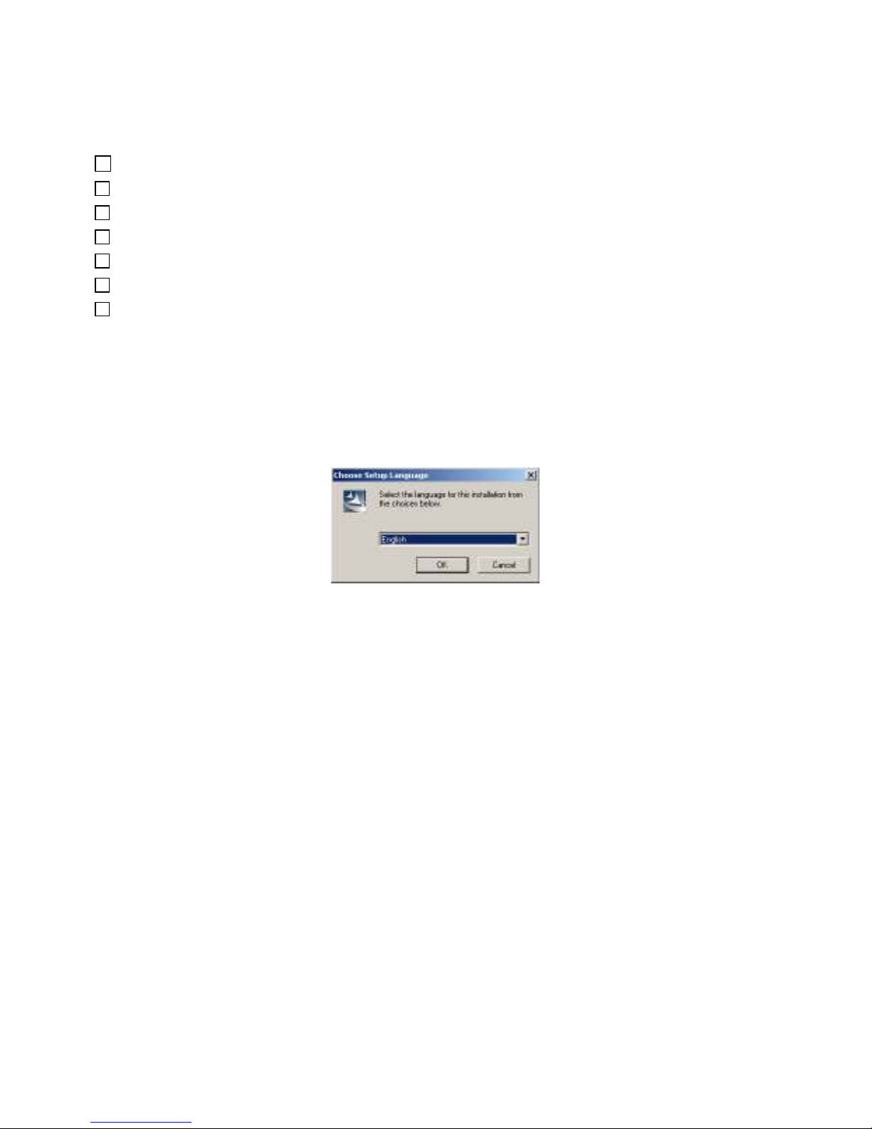
2. Select the language you prefer.
3. Click OK to install the application.
Click Exit to close the installation main screen.
4.
5. Connect the external USB enclosure with the recorded files to the PC. Also, user can install the hard
disk that contains recorded files inside the PC.
51
Page 58

i
4.3 Running the USB Playback Console
To run the application, click the icon on the PC desktop. The USB Playback Console Interface will
be different according to the file type
(DVR Recorded File (HD)
or
Backup File (.dvr))
Name Function
(1) Split Screen Mode Select from different screen view to playback the recorded video file of the entire
camera or one camera on the screen. If NVR server only supports 4 channels, the
channel screen 5~16 will be no video display.
(2) Exit To close the application.
(3) Progress bar Show the progress of the file being played. You may move the bar to seek to any
location of the track.
(4) Hour Buttons Select and click to playback the recorded video file on the specific time frame. The
The Hour buttons represent the time in 24-hour clock. The blue bar on top of the hour button indicates
that there is a recorded video file during that period of time. While the red bar indicates that you are
currently viewing the recorded video file.
(5) Playback Control
button
Hour button will be available when file source is
is open by
From left to right order:
Begin:
Previous:
Slower:
1/32x.
Rewind:
.
date
Move at the beginning of the recorded video file.
Go back to the previous frame by frame.
Play the recorded video file at the speed of 1/2x, 1/4x, 1/8x, 1/16x, or
Wind back the recorded video file.
Backup File (.dvr)
and backup file
Pause:
Play:
Briefly stop playing the recorded video file.
Play the recorded video file.
52
Page 59

Name Function
(5) Playback Control
button
Faster:
Next:
End:
Play the recorded video file at the speed of 2x, 4x, 8x, 16x, or 32x.
Go to the next frame by frame.
Go to the end of the recorded video file.
(6) Archive To select the video file source for playing.
- DVR Recorded File (HD): To playback the recorded video from the hard disk
which was recorded on the NVR system. (see also Chapter 4.3.2)
- Backup File (.dvr): The backup file saved in *.dvr file format. (see also Chapter
4.3.3)
- Backup File (.avf): The backup file saved to external USB storage device in *.avf
format. Select the file source folder and click OK to playback (NVRP4 does not
support *.avf file format).
(7) Status bar Display the recorded date, time and play speed.
(8) Language To switch language of function tips.
(9) Advanced Advanced functions include :
HDD Backup: open HDD Backup application. (see also Chapter 4.3.4
)
iEnhance: open iEnhance application. ( see also Chapter 5)
AVF to AVI: Transferring the AVF file to AVI file format (NVRP4 does not
support this function)
(10) Export
Export includes Snapshot, Print, Output Video Clip, and Export KML function.
Snapshot: Capture and save the screen shot either in *.jpg or *.bmp format.
Print: Print the screen shot.
Output Video Clip: Save the segmented file in *.dvr, *.mpeg, or *.avi format
(see also Chapter 4.3.1).
(11) Segment Keep a portion of the recorded video (see also Chapter 4.3.1).
(12) Full screen Use the entire area of the screen to only display the video. To return, press the right
button of the mouse or ESC on the keyboard.
When you switch to full screen in multiple-screen mode, left click to toggle to only
display one channel of video or multiple-channel mode or all.
(13) Camera ID Show the number of cameras that are being viewed. When in single screen mode,
click the camera ID number to switch and view other cameras. The Camera ID will
be available when source file is DVR Recorded File (HD).
(14) Visual Search
Search from a specific camera by Date, Hour, Minute, and Second (See also
Chapter 3.6.3). The Visual Search function will be available when file source is
Backup File (.dvr) and file open is by date.
Search for the next event or changes in the motion detector frame. You can use this
(15) Find Next
when you are using Intelligent Search or Event Search function. When file source is
DVR Recorded File (HD), the Find Next is not available.
Search from the list of activities that were recorded in event log (i.e., Sensor,
(16) Event Search
Motion, Video Loss). (See also Chapter 3.6.4) When file source is DVR Recorded
File (HD), the Event Search is not available.
53
Page 60
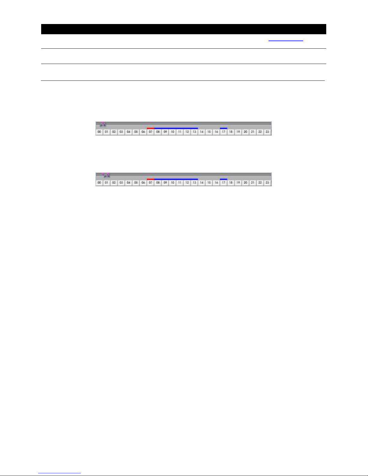
Name Function
(17) Intelligent Search
(18) Sound /Sound bar
(19) De-interlace To enhance the video quality. Set the de-interlace mode to #1 if capturing
Search the changes in the motion detector frame (See also Chapter 3.6.5). When
file source is DVR Recorded File (HD), the Intelligent Search is not available.
Turn on and off sound
Increase and decrease the volume
motionless picture and #2 if capturing lots of movement.
4.3.1 To Cut and Save the Portion of the Recorded Video
1. Use the Playback Control buttons or drag the bar on the playback progress bar and pause
n where you want to start the segment. Then, click Segment to set the begin mark.
o
2. Use the Playback Control buttons or drag the bar on the playback progress bar and pause
on where you want to end the segment. Then, click Segment to set the end mark. To cancel
segmentation, click Segment button again.
3. Click Export > Output Video Clip button to save the segmented portion.
4. In the Save As dialog box, locate on where user wants to save the file, type the filename,
and select the video format (*.dvr, *.mpeg, or *.avi).
54
Page 61
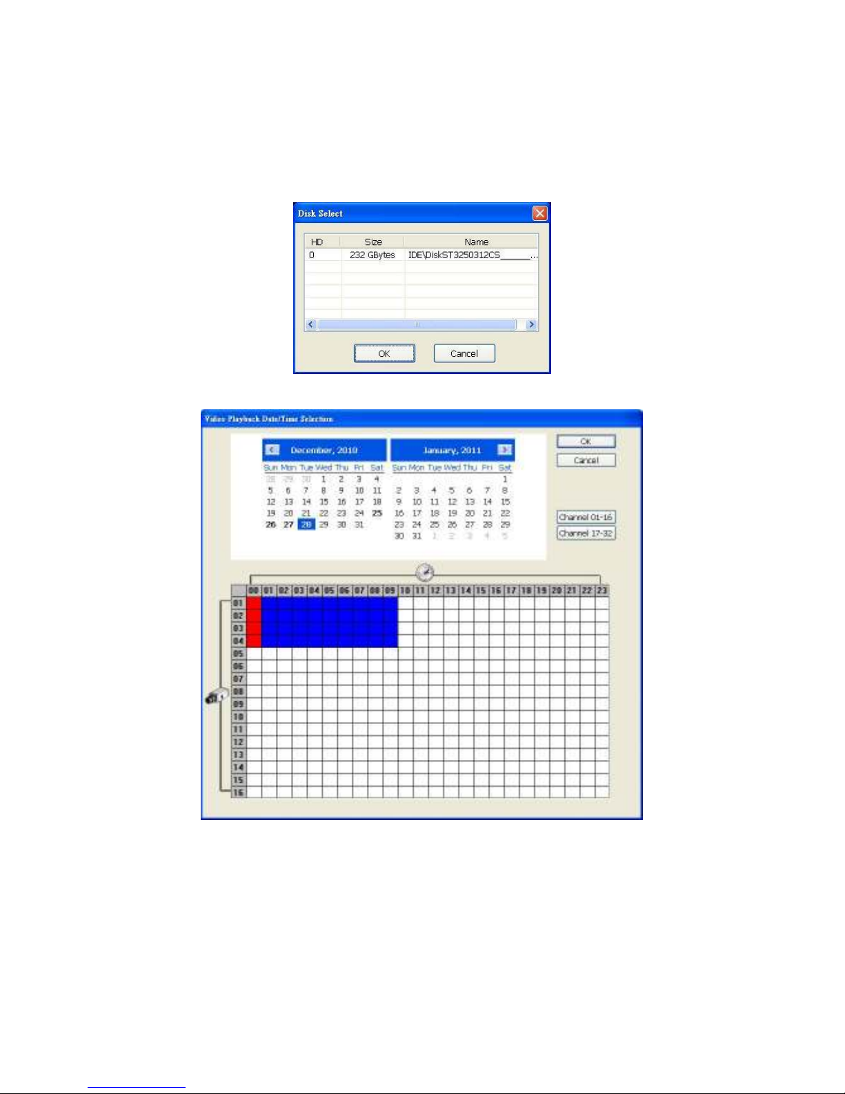
4.3.2 Playback DVR Recorded File from Hard Disk
1. Please have the hard disk which contains the recorded video data installed on your PC or use
external USB enclosure to connect to your PC.
2. Run the USB Playback Console program or click Archive from UPC program User Interface.
3. Select DVR Recorded File (HD) and click OK.
4. Select the hard disk drive from Disk Select window and click OK.
5. The Video Playback Date/Time Selection window will appear. Select the date and time and click OK.
55
Page 62

4.3.3 Playback Backup File(*.dvr)
1. Click Open File button.
2. Select Backup File (*.dvr) and click OK.
3. Select to open by date or by file.
4. Open Date: Locate the backup file and select the date folder.
5. Playback Date/Time Selection window will appear. Select the date and time and click OK.
6. Open File: Locate the backup file folder and click OK.
56
Page 63
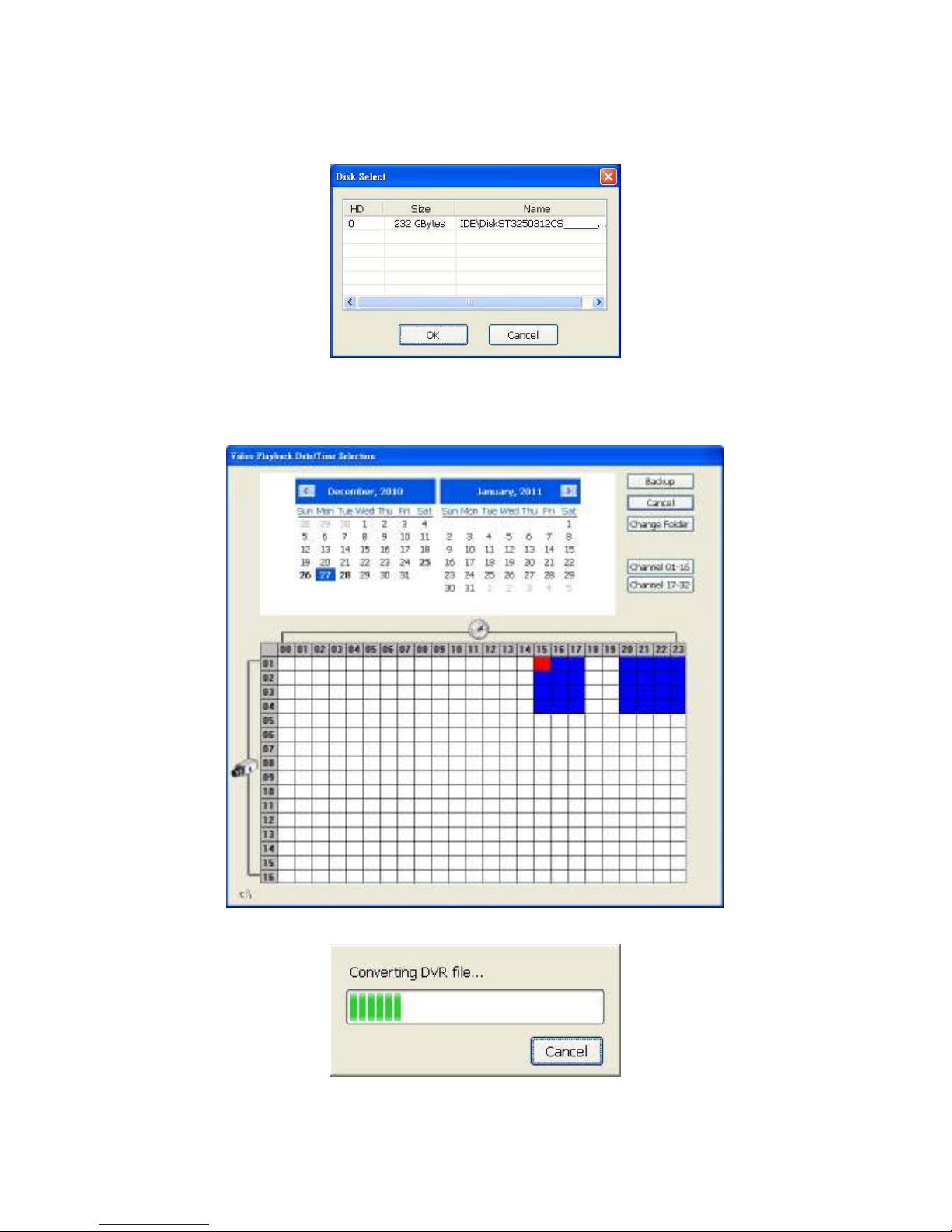
4.3.4 To Backup Recorded File
HDD backup function allows user to backup recorded file from hard disk.
1. Click Advance >> HDD Backup on UPC User Interface.
2. Select the source hard disk.
3. In Backup date/time selection window, select the date and time. 00-24 represents hours and 01-04
represents channels. Blue block means there is recorded file. Red block means the block has been
selected. Click-and-drag can select multiple blocks at once. If user wants to change the backup file
location, click Change Folder to select new save location.
4. Click Backup to start backup file.
5. When backup completes, the complete information window will display.
57
Page 64

Chapter 5 iEnhance
The bundled iEnhance is a video editing tool and can only be used with *.dvr video file. It allows you to
adjust the video picture quality, segment and save the selected portion of the video, zoom in and out, and
print or save the screen shot. You can also save the setting and apply it on other files.
To run iEnhance application, click iEnhance button on USB Playback Console interface.
(16)
(17)
(18)
(19)
(20)
(21)
(22)
(23)
(24)
(25)
(1) (2) (4)(3) (5) (6)
Name Function
(1) Open File Access *.dvr video file.
(2) Save Image Capture and save the screen shot in *.bmp format.
(3) Playback Control
From left to right order:
Buttons
Move at the beginning of the video file.
Begin:
Previous:
Go back to previous frame.
(15)
(14)
(13)
(12)
(11)
(10)
(9)
(8)(7)
Pause:
Play:
Faster:
Next:
End:
(4) Save Video Save the edited or segmented video in *.avi format.
(5) Print Print the screen shot.
(6) Segment Mark the beginning and the end of the selected portion of the video. Two triangle
marks will appear on the slider. To cancel video segmentation, click this button again.
(7) Zoom Buttons Enlarge, reduce, and set the image back to normal size.
(8) Full Screen Use the entire screen to only display the video.
(9) Default Set the video back to original state and delete all the changes in the history box.
(10) History Box List all the actions.
(11) Undo Delete the last action.
Briefly stop playing the video file.
Play the video file.
Play the video file at the faster speed.
Go to the next frame.
Go to the end of the video file.
58
Page 65

Name Function
(12) Noise Reduce Reduces the noise in the image.
(13) Sharpness Improves the overall image by enhancing edges thus providing more depth to the
image.
(14) Effects Gray Scale: converts the image into black and white (monochrome).
Normalize: adjusts the brightness intensity.
Equalize: automatically adjusts the images that are too dark.
De-interlace: smooth out the overlying frames.
Static: de-interlace for motionless scene.
Dynamic: de-interlace for moving scene.
(15) Picture
Adjustment
(16) Original Screen Display the original state of the image.
(17) Temporary
Setting Block
(18) Status Bar Display the date, and time of the video.
(19) Progress Bar Show the progress of the file being played. You may move the bar to seek to any
(20) iStable To reduce the jolt in the recorded video.(also see Chapter 5.1)
(21) Add Setting Include the new setting to the temporary setting block.
(22) Rename Change the name of the selected setting in the temporary setting block.
(23) Delete Permanently remove the selected setting in the temporary setting block.
(24) Load Setting Call the saved settings.
(25) Save Setting Store the settings in the temporary setting block.
Adjust the Brightness, Contrast, Saturation, Hue and Gamma.
Display the sample settings. Click the sample to apply the setting on the current
video.
location on the track.
5.1 To Use iStable
The iStable function can reduce the jolt in the recorded video.
1. Click Open File button and select the
recorded video.
2. And then, click iStable button.
3. iStable window will show up.
4. Select the smoothness level –
1(Low), 2, 3, 4, and 5(High). The
default value is 3.
5. Click Play button, and then iStable
function will start to initialize the
recorded video.
6. When the initialization is done, user
will see the original and stabilized
recorded video play in two windows.
59
Page 66

Chapter 6 Using the Remote Programs
User can use Microsoft Internet Explorer to access NVR system by entering the IP address. To use this
feature, make sure that the PC and NVR server are both connected to the internet and the Network
feature is enabled.
When accessing this feature for the first time, you will be prompted by the browser to install
WebCamX.cab.
Click Install when the Internet Explorer - Security Warning dialog box appears.
After installing the WebCamX.cab, connect to the NVR system. You will be prompted to enter account ID
(default is admin), password (default is admin) and the type of network. Admin has the authority to
remote setup the NVR system configuration on WebViewer.
Changing account password is strongly recommended.
i
60
Page 67

6.1 Familiarizing Yourself with the Buttons in WebViewer
Right-clicking on the WebViewer video screen, enables you to start video recording, change video quality,
switch camera and enable/disable DirectDraw.
Name Function
(1) DirectDraw Enhance the video quality.
Not all graphic cards can support this function. If you cannot see the screen displayed correctly or screen
i
is distorted, please check with VGA card vendor.
(2) Received file size Indicate the size of the data being sent per second.
(3) Camera frames Indicate the number of frames per second.
(4) One screen view To view single camera view on screen. User can right click on the screen to switch to
different camera view.
(5) Split screen view To view all cameras on screen simultaneously.
(6) Audio Enable/disable audio remotely.
(7) Record Record the video of the selected camera in AVI format. Click on the screen of the
channel to record and press Record button.
(8) Remote Console Initiate Remote Console. Allows user to control NVR server (see also Chapter 6.3).
(9) Event Log Viewer Display the Event logs, Operation logs, System logs, and Network logs.
(10) Remote setup Change the NVR server settings (see also Chapter 6.1.1)
(11) PTZ Control Initiate PTZ camera controller (see also Chapter 6.2)
(12) Snapshot Capture and save the screen shot in *.bmp format.
(13) Full screen Use the entire area of the screen to only display the video.
To return, Right click the mouse or press ESC on the keyboard.
61
Page 68

Name Function
(14) Select cameras
to view
Select to the view camera from different server. In Select Camera dialog box, Display
column, click to enable/disable viewing the camera.
Click Add Server and select the server type between NVR and IP Cam to add.
Click Delete Server to delete the selected item.
Click Import to load the previously saved list.
Click Export to save the list.
Click Apply All to change all the camera video quality based on the selected setting.
Click OK to exit.
62
Page 69

6.1.1 To Setup Remote System Setting
The setting here applies to Remote NVR only. Click the selection to configure.
6.1.1.1 System Setting
In the System Setting window, click Update to accept the new settings, click Exit to exit without
saving, and click on Default to revert to the factory default values.
(4)
(5)
(1)
(2)
(3)
(1) Delete recorded data after
If you want the system to automatically erase the data after certain days, enable the Delete recorded
data after check box and enter the numbers of days in Days text box.
(2) Delete event and alarm log after
If you want the system to automatically erase the event and alarm log files after certain days, enable the
Delete event and alarm log after check box and enter the numbers of days in Days text box.
(3) Overwrite Enable
When the recording space is not enough to record one hour of data, the system will automatically replace
the oldest data with the newest recorded data.
(4) Miscellaneous
Enable the conditions in Miscellaneous section you want the system to perform.
- Playback Mode
Select the mode of playback for the video.
Select date and time: Playback the recorded video beginning from the selected date and
time.
Play the last file: Automatically playback the video from the last hour
Instant Playback: Automatically playback the video which has just been recorded
- Date Format
63
Page 70

Select the date format which will display in Select date and time playback mode
- Auto Scan Period
Set the time gap of the Auto Scan function from 3 to 10 seconds. This automatically switches to the
next video in cycle depending on the set time gap.
(5) Login
Enable the conditions in Login section you want the system to automatically carry out.
- Auto Record after system boot up
Automatically start video recording when the NVR is powered on.
- Auto start Network after system boot up
Automatically connect to network when the NVR is powered on.
6.1.1.2 Camera Setting
Select the camera from remote NVR servers to modify settings. In the Camera Setting window, click
pdate to save and apply the new settings, click Exit to exit without saving.
U
IP Camera Setting
(1)
(2)
(3)
(4)
(5)
(1) Camera Icons
Select the camera number to adjust the video setting. To select all cameras, enable the ALL check box.
To select more than one camera, Right click on the camera icon. To select one camera only, Left click on
the camera icon. The camera icon turns red when it is selected.
(2) Enable
Set to enable/disable the selected camera. When there is no video source on the camera, we suggest
disabling it so that the system will not detect it as video loss error.
(3) Input
Select the type of camera as IP camera. To modify camera of remote NVR, see Remote NVR Camera
Setting.
(4) Camera
- Display
Enable/disable to show the video. Even if the video of the selected camera is hidden you can still
record the video and preview it in playback mode.
64
Page 71

- Enable Audio
Enable/disable audio of the camera.
- Name
Change the camera name
- Description
Add a short comment
(5) IP Camera Information
Click IP Setting to setup the parameters of the IP camera.
1. Select the Protocol, Model, Video Format, and Channel of the IP camera.
2. Enter IP address and connecting port in IP Camera Site column.
3. Also, user can enter URL of IP camera instead of IP address.
4. If the IP camera has authority request, please enable Authentication and enter ID and
Password.
5. Click OK to connect with the IP camera.
65
Page 72

Remote NVR Camera Setting
Select the camera to modify settings. In the Camera Setting window, click Update to save and apply the
new settings, click Exit to exit without saving.
(1)
(2)
(3)
(4)
(5)
(1) Camera Icons
Select the camera number you want to view. To enable/disable all cameras, click ALL check box.
(2) Enable
Set to enable/disable the selected camera. When there is no video source on the camera, we suggest
disabling it so that the system will not detect it as video loss error.
(3) Input
Select the camera type as Remote NVR. For IP camera setting, see IP Camera Setting
(4) Camera
- Display
Enable/disable to show the video. Even if the video of the selected camera is hidden you can still
record the video and preview it in playback mode.
- Enable Audio
Enable/disable audio of the camera.
- Name
Change the camera name
- Description
Add a short comment
- IP
Enter the IP address of the camera
- Port
The port for connection
- User ID
Enter the user id that for connecting authority
- Password
Enter the password that is for connecting authority
- Channel
.
66
Page 73
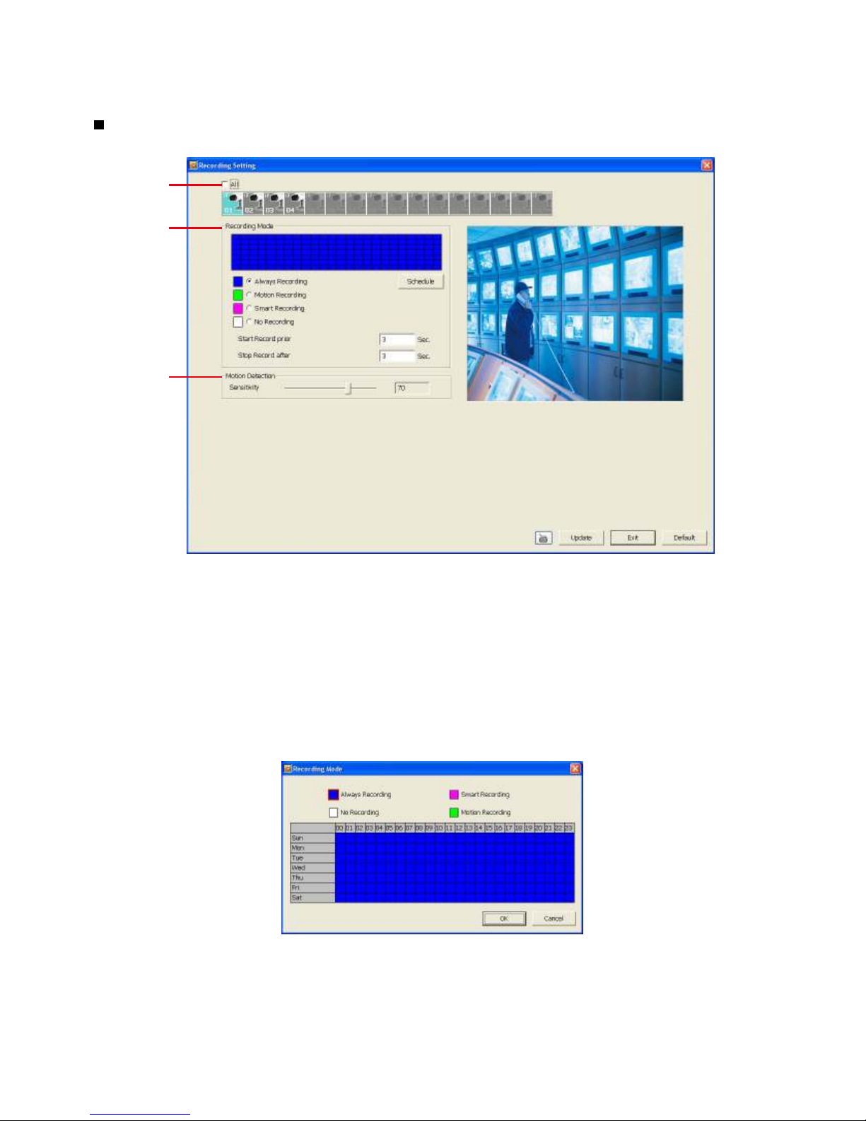
Select the channel of connected camera
6.1.1.3 Record Setting
In the Recording setup window, click OK to accept the new settings, click Exit to exit without saving,
and click on Default to revert to the factory default values.
(1)
(2)
(3)
(1) Camera Icons
Select the camera number you want to set the recording setting. To select all the cameras, enable the
ALL check box. To select more than one camera, Right click on the camera icon. To select one camera
only, Left click on the camera icon. The camera icon turns purple when it is selected.
(2) Recording Mode
The horizontal blocks from 00 to 23 represent the time in 24-hour clock and the vertical block 1 to 7
represent the day in the week block (Sunday to Saturday). To record in full 24 hours and 7 days a week,
select the recording mode and click the button. If you want to only record at a particular time or day,
click Schedule button and select the Recording Mode , and then click on the time or day blocks. When
the system starts recording a red triangle mark would appear at the upper left corner of the screen.
The recording modes are listed below:
Always Recording
-
Record the video from the selected camera and save it to the designated storage path
- Motion Recording
Start recording the video from the selected camera only when the system detects movement. Once
motion is detected, the system automatically saves the previous frames and stop based on the
67
Page 74

Start Record Prior and Stop Record After settings.
- Smart Recording
Automatically switch to record at the maximum frame rate setting when motion is detected and
switch to minimum frame rate setting when there is no motion.
- No Recording
The system will not do any recording.
(3) Motion Detection
Adjust the sensitivity of the motion detection. The higher the value, the finer motion is detected. When it
detects motion, a green triangle mark would appear at the upper left corner of the screen.
68
Page 75

changed, the
(1)
(2)
When user changed IP range in white list setting and it causes the IP address of PC that
server will
disconnect the connection automatically. Please change the IP address of PC to the IP range in
6.1.1.4 Network Setting
In the Network Setting dialog box, click Update to accept the new settings, click Exit to exit without
saving, and click on Default to revert to the factory default values. For the network service ports that
are used by the NVR server, please see Appendix A.
If user has changed the configuration causing the remote NVR’s IP address to be
i
remote NVR system will disconnect the remote access connection automatically.
(3)
(4)
(1) Server Name
Assign a name for the NVR unit. Alphabetical and numerical letters only.
(2) Transmitting Cameras
Select and click on the camera number in the Transmitting Camera section you want to make it
accessible via internet using WebViewer, Remote Console, PDA Viewer and JavaViewer (still image). To
select all the cameras, enable the ALL check box.
(3) Network Time Synchronization
Synchronizes the NVR system time to the network time server. Fill in the Time Server IP address or
domain name. Select the Time Zone that NVR is located. And then, check the Automatic Synchronize
time to set automatic synchronize time on a daily basis.
(4) Other Configuration
- Enable White List
An access permit list for the remote accessing of NVR server. Enter the IP address and click Add.
Or, enter a range of IP address and click Add. To delete the IP from the list, select the IP and click
Delete button. To reset the input, click Clear button.
i
connected with remote NVR server has been excluded in white list, the remote NVR
white list and re-connect with remote NVR server.
69
Page 76
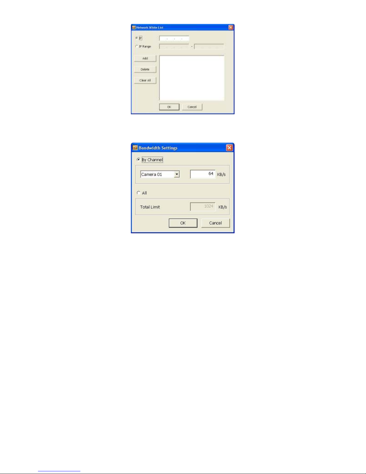
- Network Bandwidth Limit
By Channel: Set the network bandwidth limit by each channel.
All: Set the total network bandwidth consumption limit.
70
Page 77
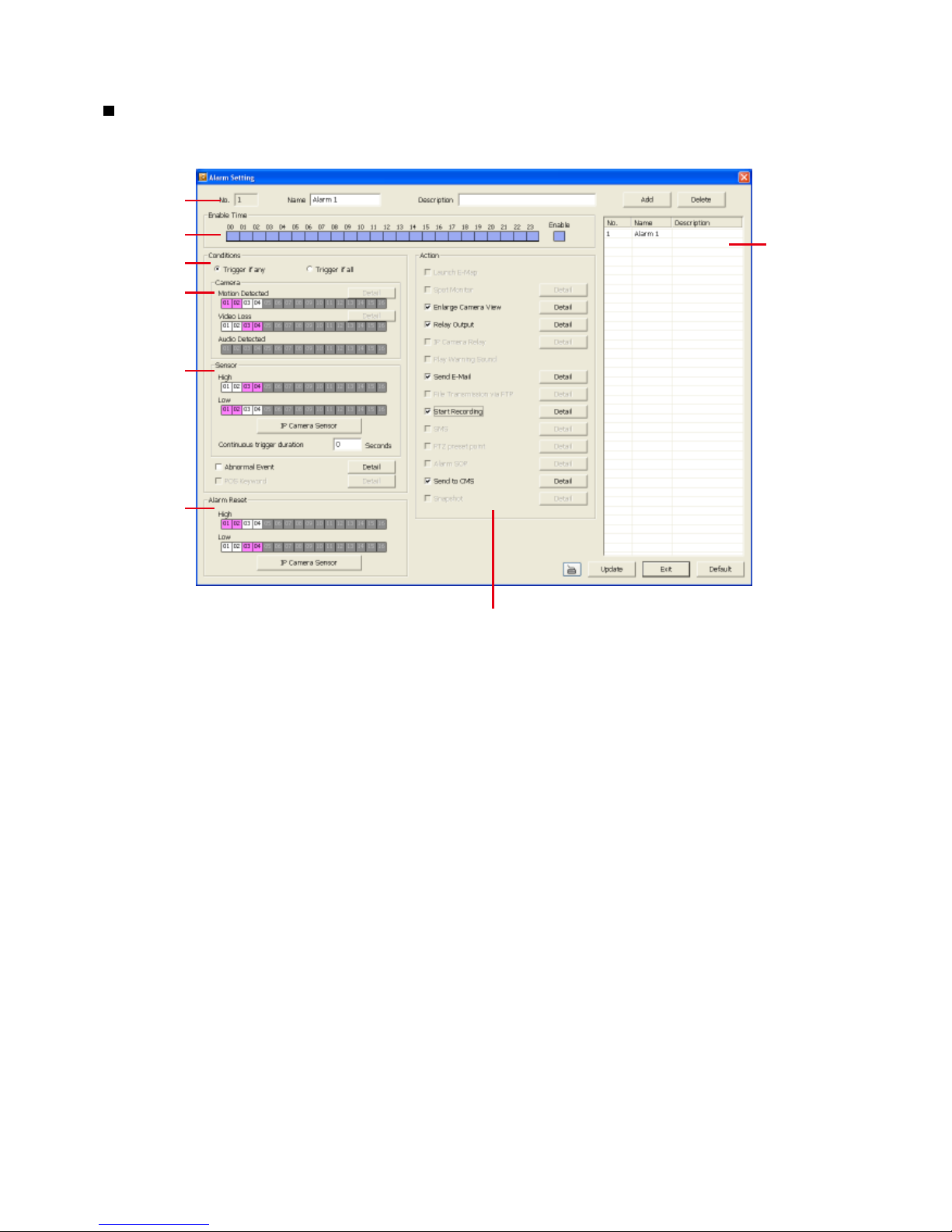
6.1.1.5 Alarm Setting
In the Alarm Setting dialog box, click Add to insert and set new alarm setting, click Delete to remove
the selected alarm setting, click Update to save the setting, Exit to exit without saving, and click on
Default to revert to the factory default values.
(1)
(2)
(3)
(4)
(5)
(6)
1. Click A
(7)
dd to add a new alarm setting. Click the items in (8) Alarm Setting List if you want to modify
(8)
the alarm setting.
2. In (1) No./Name/Description enter alarm name and description. Alarm No. will be created by NVR
system.
3. In (2) Enable Time, the number from 00 to 23 represent the time in 24-hour clock. Select the time and
click the block you want to activate or deactivate the alarm function. When it is deactivated, the color
of the block turns white.
4. In (3) Conditions, you can set “Trigger if any” to activate if it falls under one of the conditions or
“Trigger if all” to activate if it falls under all conditions.
5. In (4) Camera section, select and click on the camera number (01 to 04) in Motion Detected and
Video Loss to set the condition for the system to alarm.
6. In (5) Sensor, select and click on the sensor number to set the condition for the system to alarm. If the
sensor normal status is high, set the sensor condition to low.
- Enable/disable the Abnormal Event check box, to set the condition of the event for system to
alarm.
Reboot: when the NVR system reboots under normal condition, the system will send out the
alarm message.
Abnormal Reboot: when the NVR system reboots under abnormal condition, the system
will send out the alarm message.
Recording is switched off: when the recording has been stopped, the system will send out
the alarm message.
Network is switched off: when the network connection of NVR system is lost, the system
will send out the alarm message.
Hard Disk failed: when the hard disk does not work normally, the system will send out the
71
Page 78
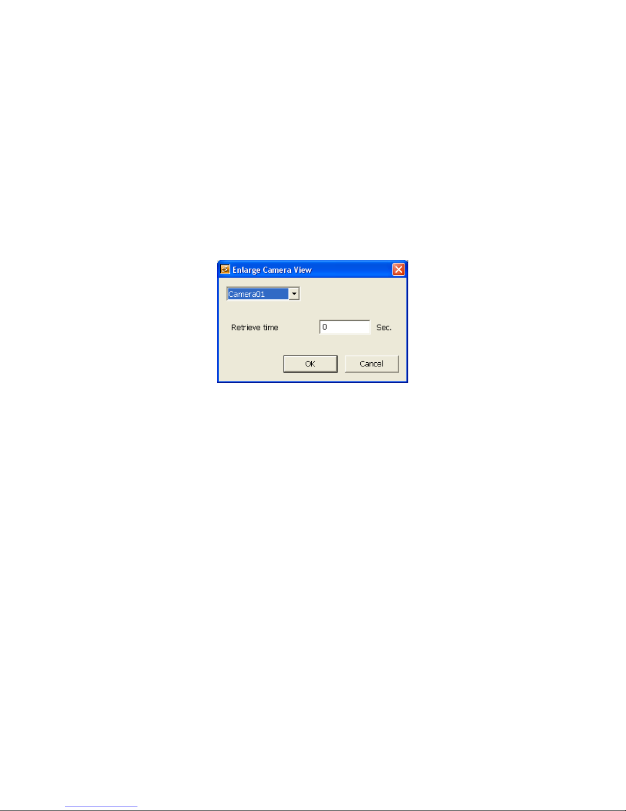
alarm message.
- Continue trigger duration: Set up the trigger duration time. If the sensor is triggered and stays
triggered for this period of time, the alarm will be sent.
7. In (6) Alarm Reset, click the camera number to reset the condition of the alarm. Once alarm is reset,
all alarm action will stop at the moment. If the sensor’s status is normally high, the alarm will reset to
low.
8. In (7) Action, you may now set the alarm action for the system to perform when the alarm condition is
activated.
- Enlarge Camera View
Switch to only display video in Preview mode from where the alarm is activated.
a. Select the camera from drop down list to specify which camera video to be enlarged on the
screen when the alarm is triggered.
b. Retrieve time: set the time duration before system switches back to original Preview mode. If
the retrieve time is un-checked, the alarm video will stay enlarged until user switches back to
Preview mode manually. The retrieve time range is 0~ 600 seconds.
- Relay Output
Set to enable/disable the relay operation when the alarm is activated and to extend additional time
in second before it stops the relay operation.
Enable/disable the relay operation when the alarm is activated and to extend the duration of the
relay output time.
1. Next to the Relay Output check box, click Detail.
2. In the Alarm Relay dialog box, select from the available relay list and in the ON column, set to
enable/disable the relay operation when the alarm is activated.
3. In the Retrieve time check box, you may enable/disable to extend the duration of the relay
output and set the duration in second.
4. Click OK to exit and accept the setting or Cancel to exit without saving the setting.
72
Page 79
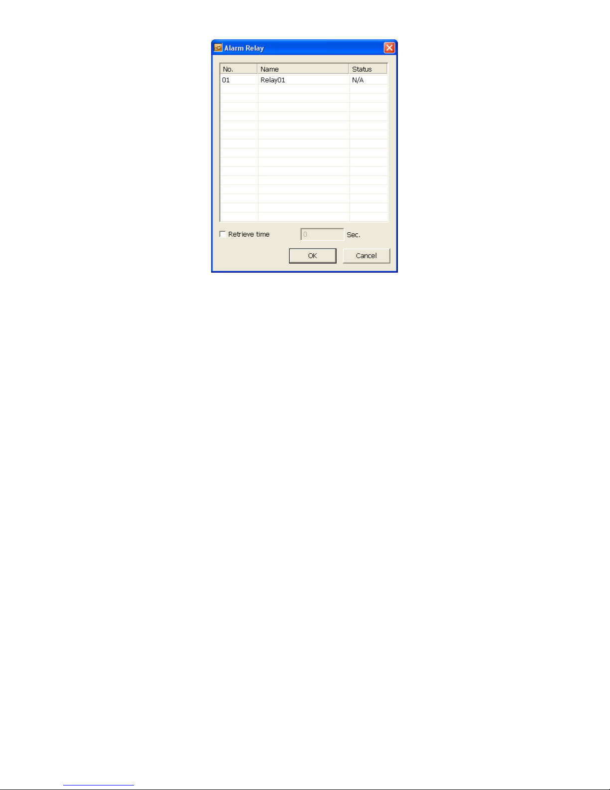
73
Page 80

- Send E-mail
Send an electronic message. Next to the Send Email check box, click Detail.
In the E-mail Setting dialog box, click OK to exit and save the setting or Cancel to exit without
saving the setting.
(1)
(2)
(1) Mail Server
Enter the SMTP Server and port. If your e-mail system requires user identification, enable
Authentication check box and enter ID and Password.
(2) Mail
Fill the mailing information.
From: Enter the sender e-mail address.
To and CC: Enter the recipient email address and separate it with comma or a semicolon (;).
Subject: Enter the message title.
Message: Type the message.
- Start Recording
Record the video from the selected camera.
Next to the Start Recording check box, click
1.
Detail.
2. In the Alarm Recording Setting dialog box,
select the camera to enable/disable video
recording. Enable All to select all cameras.
3. In the Frame Rate selection, select As
Setting to record the number of frames
based on the Recording Setting.
4. In the Start Record prior text box, check
and set the time in seconds for the program
to begin recording before the alarm is
triggered. The time range is 1~10 seconds.
5. In the Stop Record after tex
continue recording after the alarm condition has ended. The time range is 1~999 seconds. If
Stop Record after is not checked, the alarm recording will continue to record until alarm is
reset.
6. Click OK to accept the new settings or Cancel to exit without saving.
t box, check and set the time in seconds for the program to
74
Page 81

- Send to CMS (Central Management System)
- Enable/disable the selected camera to send video to CMS when the alarm is activated.
- Next to the Send to CMS check box, click Detail. In the CMS Setting, select the camera to
enable/disable sending the video to CMS. Enable All to select all cameras. Then, click OK to
accept the new settings or Cancel to exit without saving.
75
Page 82

)
6.2 Familiarizing Yourself with the Buttons in WebViewer
PTZ
(1)
(2)
(3
(4)
(5)
(6)
Name Function
(1) Direction buttons Adjust and position the focal point of the PTZ camera. Click the center to pan
automatically.
(2) Zoom +/- Zoom in and out of the image.
(3) Select PTZ Choose to enable/disable the PTZ camera. In the Select PTZ dialog box, Select
column, click to enable/disable viewing and controlling the PTZ camera.
Click OK to exit and save the setting or Cancel to exit without saving the setting.
(4) Focus +/- Adjust the focus manually to produce clear image.
(5) AutoPan Groups Operate the PTZ cameras automatically based on the selected camera group preset
position number.
(6) Camera preset
position number
Move the PTZ camera to the preset point. The reset point is based on the user setup by
remote control at local site.
76
Page 83

6.3 Familiarizing Yourself with the Buttons in Remote
Console
Name Function
(1) Exit Close the Remote Console.
(2) Split Screen
Mode
(3) Record Start/stop video recording.
(4) Network Enable/disable remote system access. This feature allows you to access NVR server
(5) Setup Configure the Remote Console setting. (see also Chapter 6.3.1)
(6) PTZ Access PTZ control panel (see also Chapter 6.3.2).
(7) Preview Switch to Preview/Playback mode. This allows you to view live camera display.
(8) Playback Switch to Playback mode. This allows you to view the recorded video file. (see also
(9) Status Bar Display the current date, time and hard disk free space.
(10) Camera ID Show the number of cameras that are being viewed. When you are in single screen
(11) Event Log Display the Event logs, Operation logs, System logs, and Network logs.
(12) Snapshot Capture and save the screen shot either in *.jpg or *.bmp format.
(13) Auto Scan Start/stop video screen cycle switch.
(14) Full screen Use the entire area of the screen to only display the video.
(15) Alarm Alert and display warning info. Administrator and user both can reset the alarm.
(16) Audio button Enable/disable the sound.
(17) DirectDraw Enhance the video quality.
Select from 1, 4, or 7+1 split screen type to playback the recorded video file.
from a remote location via internet connection.
Chapter 6.4)
mode, click the camera ID number to switch and view other camera.
To return, Right click the mouse or press ESC on the keyboard.
77
Page 84
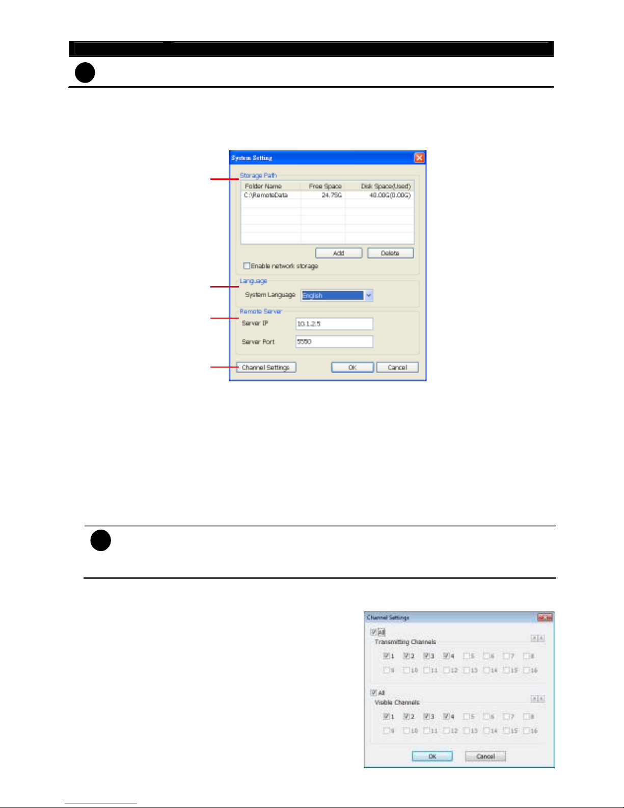
Name Function
Direct Draw function supports certain VGA card. For more information, please contact your VGA card
i
vendor.
6.3.1 To Setup Remote Console Setting
Click Setup button to open System Setting window. Click OK to exit and save the setting or Cancel to
exit without saving the setting.
(1)
(2)
(3)
(4)
(1) Storage Path
Set the directory where the recorded data will be saved. When there is not enough free space to
record one hour data, the system automatically replaces the oldest data. In case you have more than
one storage path, the system automatically saves the data to the next storage path. By default the
data is stored in C:\RemoteData, to insert another storage path, click Add. To remove the selected
path, click Delete.
- Enable network storage
elect the Enable network storage check box to send the recorded video in network-attached
S
storage.
To add network storage, the Internet storage drive/folder must be mapped as Network Driver
i
in NVR server. To know how to assign or connect to a network drive, please refer to your
Windows help file and search “Map Network drive”.
(2) Language
Customize the system to display the tool tips and dialogs based on the selected language. By default
the language is in English.
(3) Remote Server
Enter the NVR Server IP and Server Port number.
(4) Channel Settings
The numbers from 1 to 4 represent the camera ID. In
Transmitting Channels section, enable the camera number to
receive the camera signal from the server. In Visible Channels
section, enable the camera number to view the camera signal
on Remote Console screen. To select all the cameras, enable
the ALL check box.
78
Page 85

)
(2)(3)(4)(5
)
(
(
6.3.2 Familiarizing Yourself with the Buttons in PTZ Camera
Controller
(1)
6)
7)
(8) (9) (10)
Name Function
(1) Close Exit PTZ camera controller.
(2) Setup Configure PTZ cameras.
(3) AutoPan Operate the PTZ cameras automatically based on the selected camera group preset
position number.
(4) Focus +/- Adjust the focus manually to produce clear image.
(5) Zoom +/- Zoom in and out the image.
(6) Direction buttons Adjust and position the focal point of the PTZ camera.
(7) Camera ID pane Display the PTZ camera number that is being operated.
(8) Save Camera
preset position
(9) Camera lens
speed controller
(10) Camera preset
position number
(11) Group AutoPan Select to automatically operate PTZ camera in group.
Save the PTZ camera preset position number. Select the camera and click the preset
position number and save it.
Adjust the moving speed of the PTZ camera lens.
Move the PTZ camera to the preset point.
(11
79
Page 86

6.4 Using the Remote Playback
To use this feature, first you need to select the source of the file. In the Select Playback Mode dialog box,
choose Local Playback to open the file that is recorded in the Remote Console, and Remote Playback
to open the file that is recorded in the NVR server. When you choose Remote Playback, select RealTime
Playback if your internet bandwidth is large enough, otherwise choose Download and Playback.
Click OK to proceed or Cancel to void this operation.
In the Video Playback Date/Time Selection, the number from 00 to 23 represent the time in 24-hour clock.
The numbers from 01 to 04 represent the camera number.
To Make a Selection:
1. Select the date in the calendar. Use and buttons to shift the calendar to the left or right.
2. In the table below, click on the blue block to select and open the recorded file. The blue block turns
red when it is selected. The block that appears in white does not have data. You can only select one
block when you choose Download and Playback.
3. Click OK to proceed or Cancel to void this operation.
4. If you select Download Playback and made the selection, the system divides the selected hour into 16
ideo thumbnails. In the Time Selection screen, click on the video thumbnail you want to download
v
80
Page 87
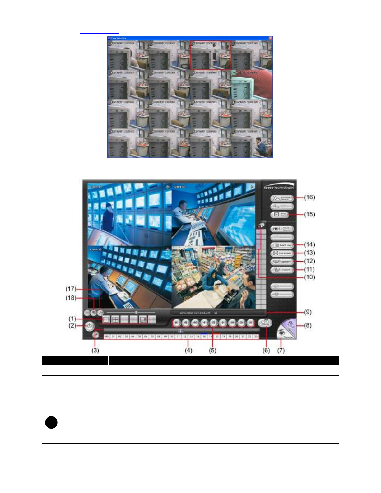
(see also Chapter 6.4.3).
6.4.1 Familiarizing Yourself with the Buttons in Local Playback
Name Function
(1) Split Screen Mode
(2) Exit
(3) Progress bar Show the progress of the file being played. You may move the bar to seek at any
(4) Hour Buttons Select and click to playback the recorded video file on the specific time frame.
The Hour buttons represent the time in 24-hour clock. The blue bar on top of the hour button indicates
i
that there is a recorded video file on that period of time. If there is no recorded data within the hour, there
will be no color bar on top of the hour button. While the red bar indicates that you are currently viewing
the recorded video file.
Select from 1, 4, or 7+1 split screen type to playback the recorded video.
To close the application
location of the track.
81
Page 88
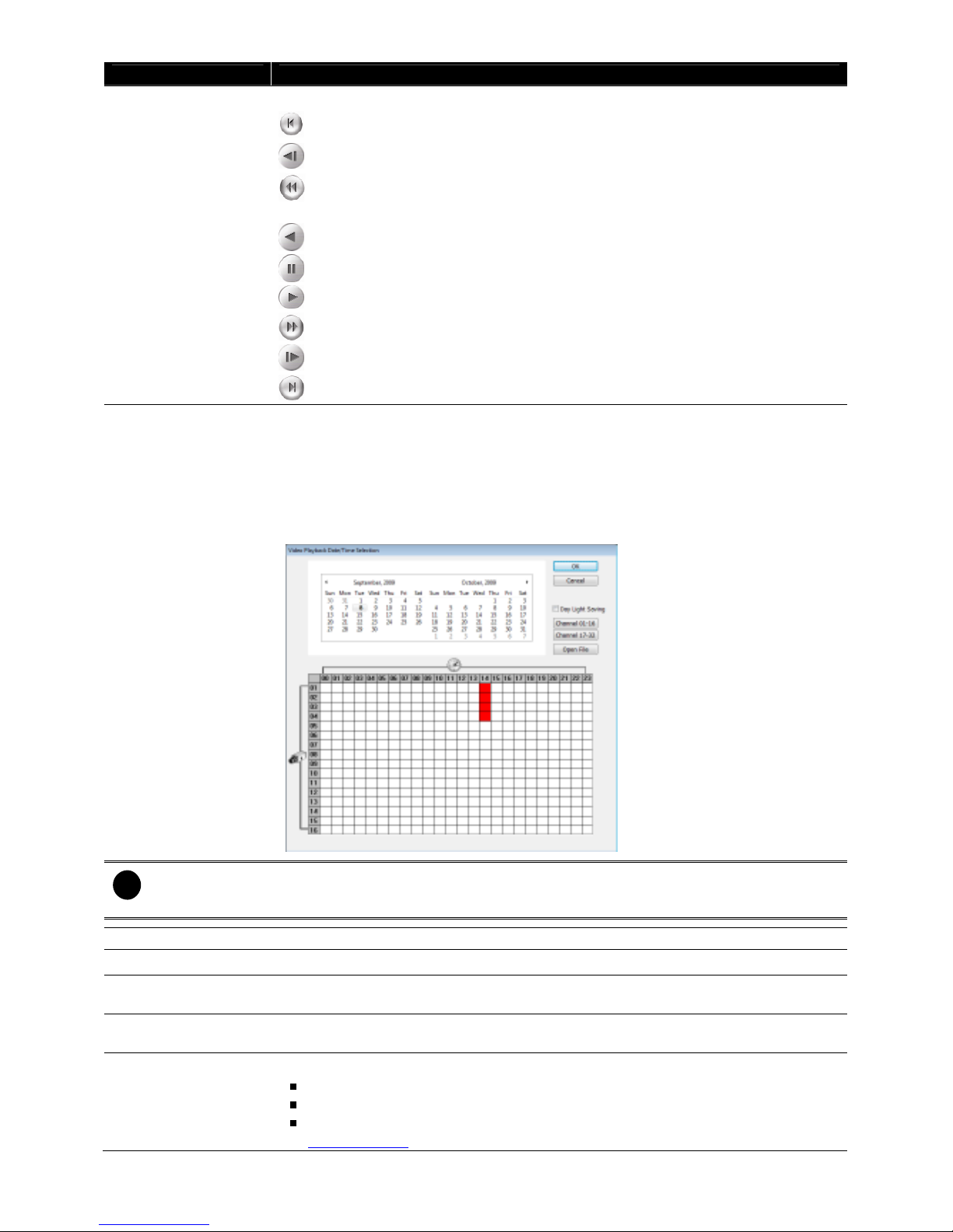
Name Function
(5) Playback Control
Buttons
From left to right order:
Begin:
Move at the beginning of the recorded video file.
Previous:
Slower:
1/32x.
Rewind:
Pause:
Play:
Faster:
Next:
End:
(6) Archive Select the date on the calendar and the time from 00 to 23 to where to start playing the
recorded video file.
– OPEN FILE: Click to open the recorded file from certain location.
– Channel 01~ 16 & Channel 17 ~ 32: Click to switch to different channel group of
playback calendar if the NVR supports more than 16 channels.
Go back to the previous frame.
Play the recorded video file at the speed of 1/2x, 1/4x, 1/8x, 1/16x, or
Wind back the recorded video file.
Briefly stop playing the recorded video file.
Play the recorded video file.
Play the recorded video file at the speed of 2x, 4x, or 8x, 16x or 32x.
Go to the next frame.
Go to the end of the recorded video file.
– Mark Day Light Saving, the playback calendar will show the available playback
records during day light saving period.
The numbers from 00 to 23 represent the time in 24-hour clock. The numbers from 01 to 04 represent the
i
camera ID. While the red colored column indicates on where to start playing the recorded video file. If
there is no any video data, it will be no color bar on top of the date button.
(7) Preview Switch to Preview mode.
(8) Playback Switch to Playback mode. This allows you to view the recorded video file.
(9) Status bar Display the record date, time, HDD capacity in preview mode and play speed in
playback mode.
(10) Camera ID Show the number of cameras that are being viewed. When you are in single screen
mode, click the camera ID number to switch and view other camera.
(11) Export Export includes Snapshot, Print, and Output Video Clip function.
Snapshot: Capture and save the screen shot either in *.jpg format.
Print: Print the screen shot.
Output Video Clip: Save the segmented file in *.dvr, *.avi, *.mpg format (see also
Chapter 6.4.1.1).
82
Page 89

Name Function
(12) Segment Keep a portion of the recorded video you want (see also Chapter 6.4.1.1).
(13) Full screen View in Playback-compact mode. To return, press the right button of the mouse or
ESC on the keyboard.
(14) Event Log Show the record of activities that take place in the system
(15) Find Next Search for the next event. You can use this when you are using Event Search
function.
(16) Intelligent Search Search the changes in the motion detector frame (See also Chapter 3.6.5).
(17) Audio Enable/disable volume
(18) De-interlace To enhance the video quality. Set the de-interlace mode to #1, if you are capturing
motionless picture and #2, if it captures lots of movement.
6.4.1.1 To Cut and Save the Wanted Portion of the Recorded Video
1. Use the Playback Control buttons or drag the bar on the playback progress bar and pause on where
you want to start the segment. Then, click Segment to set the begin mark.
2. Use the Playback Control buttons or drag the bar on the playback progress bar and pause on where
you want to end the segment. Then, click Segment to set the end mark. To cancel segmentation or
set the segment marks from the start, click Segment button again.
3. Click Export >> Output Video Clip button to save the wanted clip.
4. In the Save As dialog box, locate on where you want to save the file, type the filename, and select the
video format.
83
Page 90
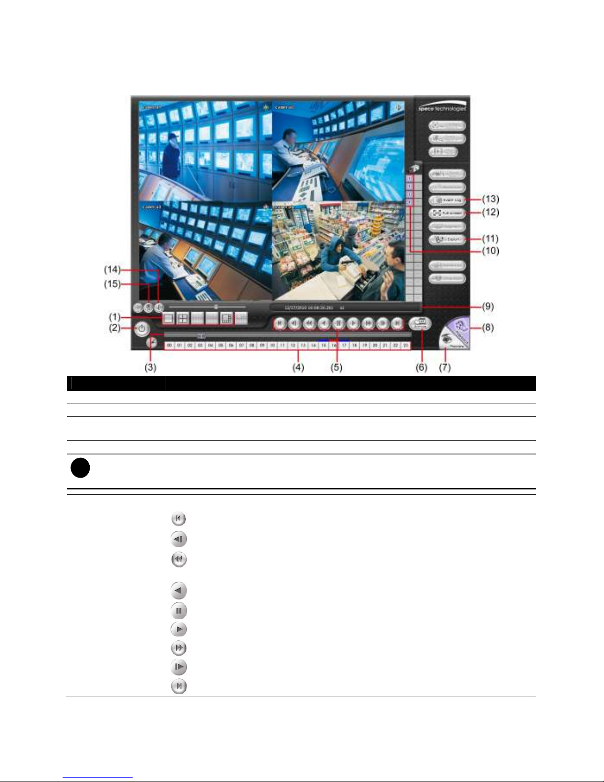
6.4.2 Familiarizing Yourself with the Buttons in RealTime
Playback
Name Function
(1) Split Screen Mode Select 1, 4, or 7+1 split screen type to playback the recorded video file.
(2) Exit
(3) Progress bar Show the progress of the file being played. You may move the bar to seek at any
(4) Hour Buttons Select and click to playback the recorded video file on the specific time frame.
The Hour buttons represent the time in 24-hour clock. The blue bar on top of the hour button indicates
i
that there is a recorded video file on that period of time. While the red bar indicates that you are currently
viewing the recorded video file.
(5) Playback Control
Buttons
To close the application
location of the track.
From left to right order:
Begin:
Previous:
Slower:
1/32x.
Rewind:
Pause:
Play:
Faster:
Move at the beginning of the recorded video file.
Go back to the previous frame.
Play the recorded video file at the speed of 1/2x, 1/4x, 1/8x, 1/16x, or
Wind back the recorded video file.
Briefly stop playing the recorded video file.
Play the recorded video file.
Play the recorded video file at the speed of 2x, 4x, or 8x, 16x or 32x.
Next:
End:
Go to the next frame.
Go to the end of the recorded video file.
84
Page 91

Name Function
(6) Archive Select the date on the calendar and the time from 00 to 23 to where to start playing the
recorded video file.
– OPEN FILE: Click to open the recorded file from certain location.
– Channel 01~ 16 & Channel 17 ~ 32: Click to switch to different channel group of
playback calendar if the NVR supports more than 16 channels.
– Mark Day Light Saving, the playback calendar will show the available playback
records during day light saving period.
The numbers from 00 to 23 represent the time in 24-hour clock. The numbers from 01 to 04 represent the
i
camera ID. The blue colored column indicates that there is a recorded video file on that period of time.
While the red colored column indicates on where to start playing the recorded video file.
(7) Preview Switch to Preview/Advanced mode.
(8) Playback Switch to Playback mode. This allows you to view the recorded video file.
(9) Status bar Display the recorded date, time and play speed.
(10) Camera ID Show the number of cameras that are being viewed. When you are in single screen
mode, click the camera ID number to switch and view other camera.
(11) Export Snapshot: Capture and save the screen shot either in *.jpg or *.bmp format.
(12) Full screen View in Playback-compact mode. To return, press the right button of the mouse or ESC
on the keyboard.
When you switch to full screen in multiple-screen mode, Left click to toggle to only
display one of the video in the multiple-screen mode or all.
(13) Event Log Show the record of activities that take place in the system
(14) Audio Enable/disable volume
(15) De-interlace To enhance the video quality. Set the de-interlace mode to #1, if you are capturing
motionless picture and #2, if it captures lots of movement.
85
Page 92
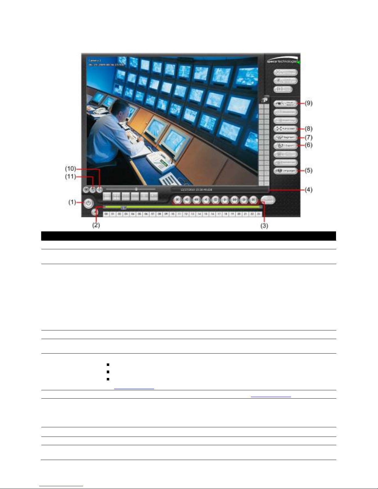
6.4.3 Familiarizing Yourself with the Buttons in Download and
Playback
Name Function
(1) Exit To close the application.
(2) Progress bar Show the progress of the file being played. You may move the bar to seek at any location
of the track.
(3) Playback Control
Buttons
(4) Status bar Display the recorded date, time and play speed.
(5) Language Customize the system to display the tool tips and dialogs based on the selected
(6) Export Export includes Snapshot, Print, and Output Video Clip function.
(7) Segment Keep a portion of the recorded video you want (see also Chapter 6.4.1.1).
(8) Full screen View in Playback-compact mode. To return, press the right button of the mouse or ESC
(9) Visual Search Search from a specific camera by Date, Hour, Minute, 10 Seconds and Second.
(10) Audio Enable/disable volume
(11) De-interlace To enhance the video quality. Set the de-interlace mode to #1, if you are capturing
Begin: Move at the beginning of the recorded video file.
Previous: Go back to the previous frame.
Slower: Play the recorded video file at the speed of 1/2x, 1/4x, 1/8x, 1/16x, or 1/32x.
Rewind: Wind back the recorded video file.
Pause: Briefly stop playing the recorded video file.
Play: Play the recorded video file.
Faster: Play the recorded video file at the speed of 2x, 4x, or 8x, 16x or 32x.
Next: Go to the next frame.
End: Go to the end of the recorded video file.
language. By default the language is in English.
Snapshot: Capture and save the screen shot either in *.jpg or *.bmp format.
Print: Print the screen shot.
Output Video Clip: Save the segmented file in *.mpg, *.avi, or *.dvr format (see also
Chapter 6.4.1.1).
on the keyboard.
When you switch to full screen in multiple-screen mode, Left click to toggle to only
display one of the video in the multiple-screen mode or all.
motionless picture and #2, if it captures lots of movement.
86
Page 93
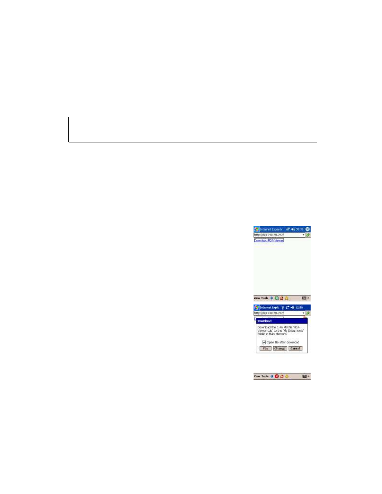
Chapter 7 Using Mobile Device to Access NVR
rver
Se
7.1 Using PDAViewer to Access NVR Server
Users can also use a PDA to access the NVR through the internet. Make sure that your PDA supports IE
er and is connected to the internet. To use this feature, you need to install the PDA Viewer software
brows
either thru ActiveSync connection or download it from the internet. Please check if your PDA meets the
requirements below.
OS: Microsoft Pocket PC 4.20.0, Windows Mobile6 Professional CE OS
5.2.1437, MS Windows CE 4.0, PocketPC 2002/2003, Mobile 5 PDA version
CPU: ARM architecture
7.1.1 To install PDAViewer thru ActiveSync
1. Connect your PDA to your PC. Place the CD into the CD-ROM drive then click Install Web Tool >> PDA Viewer
>> PDAViewer.exe. And follow the on-screen instructions.
2. Click next to continue. The system will then automatically install the application.
3. When you are prompted, click Yes to install the application using the default directory.
7.1.2 To install PDAViewer from the Internet
Make sure you are connected to the internet.
1. Open the web browser and enter the server IP. Then click the
hyperlink Download PDAViewer.
2. When the Download dialog box appears, enable Open file after
download and click Yes.
87
Page 94

3. After the installation, the PDAViewer icon will appear in the
Programs list.
88
Page 95
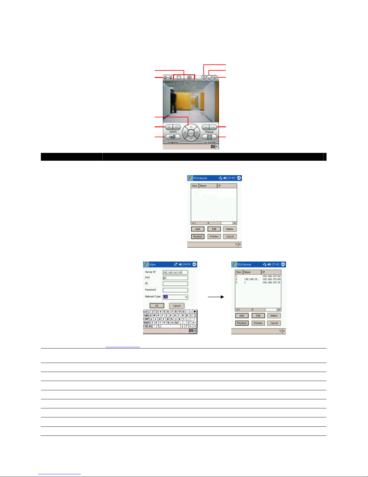
(3)
7.1.3 To Use the PDAViewer
1. Run the PDAViewer in the Programs.
2. Familiarizing Yourself with the Buttons in PDAViewer
(2)
(1)
(4)
(5)
(10)
(9)
(8)
Name Function
(1) Connect Hook up to the NVR server. Make sure you are connected to the internet.
When the iView screen appears, click Add to add the NVR server.
(6)
(7)
Enter the server IP, port, user ID, password and select the connection type. Then, click
OK.
User can playback the recorded video from remote NVR server in PDAViewer.(see also
Chapter 7.1.4)
(2) Split Screen Mode Select between 2 screen display types. It also allows you to switch and view different
camera number or channels.
(3) About Display the PDAViewer software version.
(4) Minimize Reduce the size to taskbar.
(5) Exit Close the PDAViewer.
(6) Focus Adjust the focus of PTZ camera to produce clearer image.
(7) Full Screen Use the entire screen to only display the video.
(8) Snapshot Capture and save the screen shot in *.bmp format.
(9) Zoom Zoom in and out the PTZ camera image.
(10) Direction buttons Adjust and position the focal point of the PTZ camera.
89
Page 96

3. To change the video quality, enable/disable audio, and to display a different camera, tap on the video
screen for a few seconds and the popup menu will appear.
7.1.4 To Playback in PDAViewer
1. Run the PDAViewer in the Programs.
2. Hook up to the NVR server.
3. Click Connect icon and select the NVR server
4. Click Playback to enter playback option screen
5. Select the camera, date, and time
6. Click Playback to start playing the recorded video
7. While in playback, user can view and change status of the I/O devices
8. On the playback screen, tap on video screen and the popup menu will appear
9. Select Remote IO
90
Page 97

10. The sensor and relay devices will be listed as below:
11. User can change the relay status. Select the relay and tap on video screen for a few seconds and the
popup menu will appear, and then, select the status (ON, OFF, Trigger)
7.2 Using JavaViewer to Access NVR Server
Make sure the mobile phone supports Symbian Smart Phone OS and can be connected to the internet. Install the
JAVA Viewer program that can be downloaded with the NVR server through the internet.
7.2.1 To install JavaViewer from the NVR Server
1. Open the web browser and enter the NVR server IP (http://NVR server IP: port/JAVA-Viewer.html).
Then click Connect.
2. When the Download screen appears, select JAVA-Viewer.jad and download it to your mobile phone.
3. After the installation, the JavaViewer will be in your mobile phone system. To find where the
JavaViewer program is located, please refer to your mobile phone user’s manual.
91
Page 98

7.2.2 To Use the JavaViewer
1. Run the JavaViewer program.
2. Enter the NVR IP address, port number, user ID, and
password. Please refer to your NVR server setting for that
information.
3. And then, select the Connect button to connect to the NVR
server.
4. Click Yes to accept the data from NVR server.
5. When connection is successful, you will see the camera video
on the screen.
6. To switch to a different camera view, select menu and select
the channel.
7. The JavaViewer supports PTZ control function, you can refer
to Help file for detailed function control key. Select menu and
go to the bottom of the list to select the Help file.
→→→→
92
Page 99

keyword here
7.3 Using iPhone to Access Remote NVR Server
Using the iPhone to connect to the remote NVR server through the internet to view live image.
7.3.1 Download the SpecoPC Application
To use this feature, it is required to download the SpecoPC application to your iPhone. There are 2 ways
to download the SpecoPC application to your iPhone. User can chose either way to download.
I. Download through the PC
1. Connect your iPhone to the PC.
In iTunes Application, enter keyword “speco” to search.
2.
3. The SpecoPC application will be found and display on iTunes Application.
4. Click SpecoPC application and click GET APP to download the application. And then, enter the ID and
Password to download.
Enter the search
5. After downloading the SpecoPC application, click Application and check the SpecoPC application.
93
Page 100

6. Click Apply button. The SpecoPC application will now be loaded onto your iPhone.
7. To use SpecoPC application, select the SpecoPC application icon on your iPhone. Please refer to
Chapter 7.3.2 on how to use the SpecoPC application.
II. Using iPhone to Download
1. Please make sure your iPhone is connected to the internet.
2. Select App Store from the iPhone main screen.
3. Select Search and enter the keyword “speco” to search.
4. In the search result list, select the SpecoPC. User will see a brief introduction of the SpecoPC
application. Select the Free button, the button will change to the Install button. Select Install to
download the application.
5. And then, enter ID and Password for iTunes login to start the download process.
After download is completed, go back to iPhone main screen and user should see
6.
the menu list. Select it to run the application. Please refer to Chapter 7.3.2 on how to use the
SpecoPC application.
pecoPC
S
icon in
7.3.2 Using the SpecoPC Application
1. After SpecoPC application has been downloaded to your iPhone, select the SpecoPC application to
execute.
2. In the login screen, enter the following information to make a connection with the remote NVR server.
After all necessary information is entered, click Login.
IP: IP address of the remote NVR server.
Port: The connection port of the remote NVR server. The default value is 5550.
ID: The user account to login to the remote NVR server.
Password: The password for login authentication.
94
 Loading...