

Page 1

Intensifier Series
Camera
HTINTB1
HTINTB2
Please read this manual thoroughly before operation and keep
it handy for further reference.
Page 2

Page 3

WARNING & CAUTION
The lighting flash with an arrowhead symbol, within an equilateral triangle is
Intended to alert the user to the presence of un-insulated “dangerous voltage”
within the product’s enclosure that may be of sufficient magnitude to constitute
a risk of electric shock to persons____________________________________
The exclamation point within an equilateral triangle is intended to alert the user
to the presence of important operating and maintenance (serving) instructions
in th e l i t er a t u r e a c c om p a n y i n g t h e a p p l i anc e __ _ _ _ _ _ _ _ _ _ _ __ _ __ _
I N F O R M AT I O N - T h i s e q u i p m e n t h as b e e n te s t e d a n d f o u n d t o c om p a ny w i t h
l i m i t s f o r a c la s s a d i g i t al d e v i ce P u rs u a n t t o p ar t 1 5 o f t h e F C C r u le s .
Th e se l i m i t s a r e d e si g n e d t o p r o vi d e r e a s o na bl e p r o t e ct io n a g a i n s t h a r m f u l
I n t er f er en c e W h e n t he e q u i p m en t s o p e r a te d i n a c o m me r c ia l e n v i ro n me n t .
Thi s e q ui p m e n t g e n e ra t es , u s e s, a n d Ca n R a d i at e r a d i o f r e q u e n c y e n e r g y a n d
if n o t in s t all e d an d use d i n a c c ord a n c e w i t h t h e i n str u c t i o n m a nua l , m ay C a use
Ha r m f ul i nt e r f er e nce t o r a d i o c o mm u n ic a t i o n s. Op e r at i o n o f t hi s e q u i p me n t i n a
r e s i d e n t i a l a r e a i s l i k e l y t o c a u s e h a r m f u l i n t e r f e r e n c e i n w h i c h
Ca s e t h e u s er w il l b e re q ui r ed t o c o rr e c t th e i n t e rfe r enc e a t h is o w n e xpe n se .
WARNING – Change or modification not expressly approved by the manufacturer could void
the u ser’s authori t y to o perate the eq uipm ent_____ _______ _ ________ _____ ___ ____ _
CAUTION : To prevent electric shock and risk of fire hazards.
DO NOT use power sources other than that specified.______
DO NOT expose this appliance to rain or moisture.000
This installation should be made by a qualified service person and should conform to all local codes.
RISK OF ELECTRIC SHOCK
DO NOT OPEN
CAUTION : TO REDUC E THE RIS K O F ELECTR IC SH O CK
D O N O T R E M O V E C O V E R ( O R B A C K ).
N O U SE R S E R VI C E AB L E P AR T S I NS I DE
R E F E R S E R V I C I N G T O Q U A L I F I E D
S E RV I C E P E R SO N N EL . __ _ __ _ _ _ __ _ _ _ __
CAUTION
Page 4

Package Contents
Features
1
3
Contents
Precautions
4
Camera Installation
5
Focusing
6
7
Page 5

Operating Your Camera
Troubleshooting
SET UP
SET UP LENS
SHUTTER SPEED CONTROL
BACK LIGHT
AUTO GAIN (AGC)
WHITE BALANCE
REDUCE NOISE
INTENSIFIER
CAMERA TITLE
DAY/NIGHT/SYNC
MOTION DETECTION
PRIVACY
REVERSE
DETAIL
DEFAULT/RETURN
11
13
15
19
20
21
23
24
25
27
29
31
32
33
9
35
2
34
Specifications / Dimensions
37
Warranty
39
Page 6

PACKAGE CONTENTS
• Please make sure that the following items are included
in the package:
1 SUNSHIELD
1 REMOTE CONTROLLER
1 IR RECEIVER
4 MOUNTING SCREWS
1 M2.6 WRENCH (“L" TYPE)
1 VIDEO TEST CABLE
1 POWER CABLE ADAPTOR (for optional use)
Please leave this manual with the end-user for future
reference.
3
Page 7

PRECAUTIONS
• TO PREVENT A FIRE OR ELECTRICAL HAZARD PLEASE USE
PROPER POWER CABLE
• INSTALLATION SHOULD BE PERFORMED BY QUALIFIED
PERSONNEL
• PLEASE USE A UL APPROVED REGULATED 24 VOLT AC OR
12 VOLT DC POWER SUPPLY
• PLEASE USE APPROPRIATE LOW VOLTAGE POWER CABLE
TO PREVENT FIRE OR ELECTRICAL SHOCK.
• PLEASE INSURE THAT YOUR INSTALLATION AREA CAN
SUPPORT THE WEIGHT OF THE CAMERA.
• PLEASE HANDLE THIS CAMERA CAREFULLY:
- DON
’
T USE A STRONG OR ABRASIVE DETERGENT WHEN
CLEANING THE CAMERA.
- USE A SOFT TISSUE OR LENS CLOTH TO CLEAN THE
FRONT GLASS
- DON
’
T EXPOSE THE CAMERA TO DIRECT SUN
4
Page 8

CAMERA INSTALLATION
CONNECT POWER CABLE
1. WHEN USING 12 VOLTS DC (constant voltage 600 mA)
2. WHEN USING 24 VOLTS AC (40 Volt Amps)
3. CONNECT VIDEO CABLE
-CONNECT BNC CABLE TO THE BNC JACK.
5
POWER SUPPLY
CONNECT
YELLOW:VIDEO OUT
CONNECT
BLACK:(-)
POWER RED(+)
POWER SUPPLY
POWER I NPUT:RED
CENTER:(+)
Page 9
FOCUSING
6
1. SET THE ZOOM OR FIELD OF VIEW BY USING THE
ZOOM CONTROLLER (3-9mm or 5~50mm)
SET THE FOCUS BY USING THE FOCUS CONTROLLER.
LOCK BOTH RINGS INTO POSITION USING THE SETSCREWS.
▣ 3~9 mm
▣ 5~50 mm
VIDEO COLOR CCD CAMERA
ZOOM CONTROLLER
FOCUS CONTROLLER
VIDEO COLOR CCD CAMERA
FOCUS CONTROLLER
ZOOM CONTROLLER
Page 10

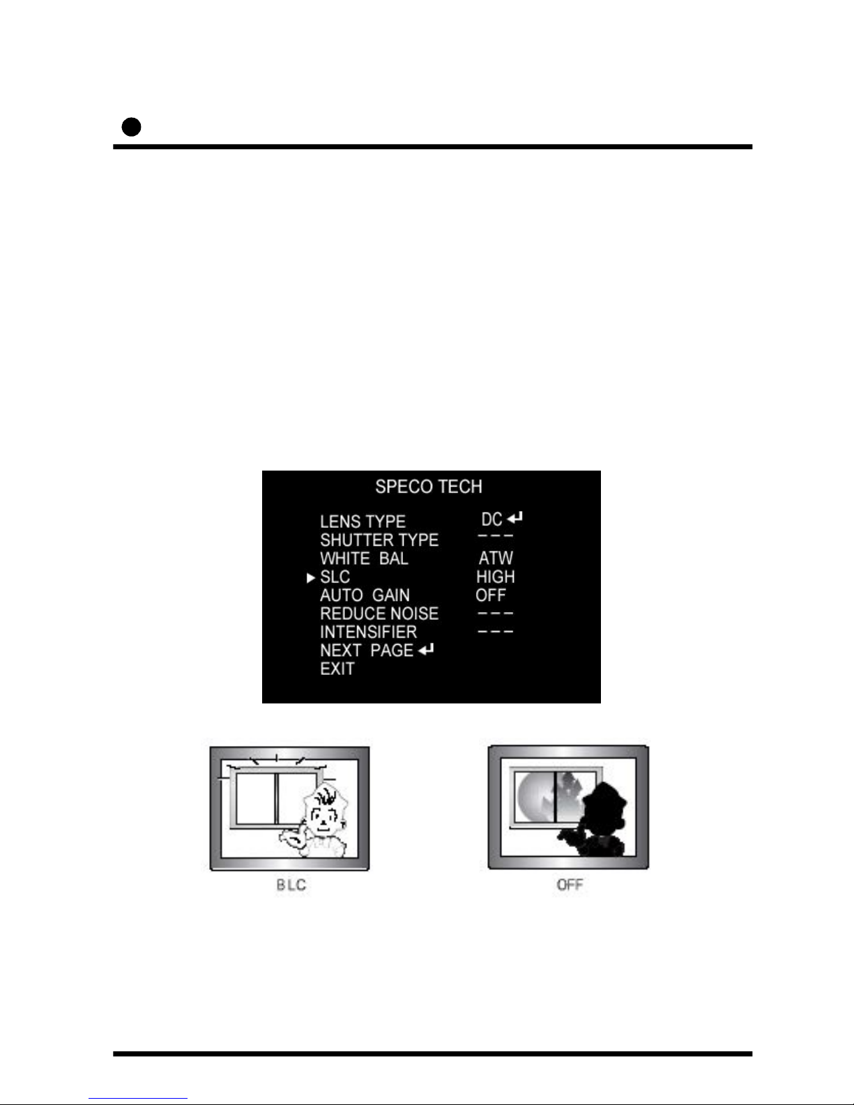
When the image is in front of strong background lighting,
your camera allows you to get the clear image.
SLC
1/3 inch density CCD and digital processor permit
high quality pictures to be captured in very low light
condition.
INTENSIFIER
Horizontal resolution of 530 TV lines is
achieved by using a SONY Double Speed CCD with
410,000 pixels, yielding pictures with a high S/N ratio..
High Resolution
Built in motion detector with adjustable areas of coverage will
flash a warning on the screen when motion is detected.
Motion Detection
Features
7
Page 11

You can control a lot function on the screen.
OSD
The Intensifier camera has a DSP chip that can
remove image noise efficiently showing clean
images in low light conditions.
Dynamic Noise Reduction
The Intensifier camera can show color pictures in all lighting
conditions, or you can have it automatically switch to a B/W
picture in low light conditions
ELECTRONIC DAY/NIGHT
The Intensifier camera will work with auto iris, manual iris and
fixed iris lenses.
MANUAL / AUTO IRIS LENS
8
Page 12

Function
Operating your camera
SETUP MENU
LENS option
●DC ●MANUAL
SHUTTER
●OFF ●F/L ●MANUAL
WHITE BALANCE
●ATW ●AWC MANUAL●
BACKLIGHT
●OFF ●LOW ●MIDDLE ●HIGH
AGC
●OFF ●LOW ●MIDDLE ●HIGH
DNR
●OFF ●LOW ●MIDDLE ●HIGH
SENSE UP
●AUTO ●OFF
SPECIAL
●CAMERA ID ●COLOR ●SYNC
●MOTION DET ●PRIVACY ●MIRROR
●SHARPNESS ●RESET ●RETURN
EXIT
9
Page 13

10
Page 14

Operating your camera
Power Connector
(DC12V in)
485(+),(-)
Baud Rate Setting
Buzzer On/Off
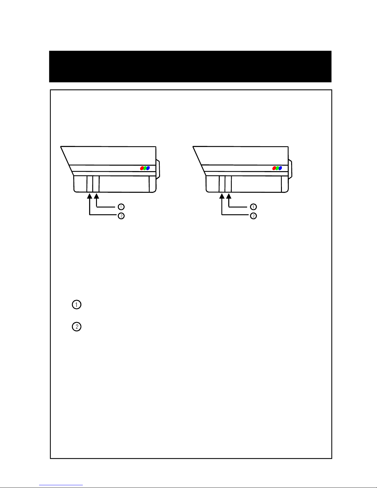
3. When you control by RS-485, Pelco-D protocol (Option), refer to the following.
A. DIP Switch Setting on the Camera
(Factory default : Camera Address = 01, Baud Rate = 2400bps)
B. Receiver Setting to use with IR Remote Controller
(Factory default : Baud Rate = 2400bps, Chart is same as above)
•15 Cameras can be controlled
by 1 IR Remote Controller &
1 Receiver. So you need to set
up each camera’s address by
DIP Switch on the camera
RS485 Address Set①
RS485 Baud rate Set
②
11
Page 15

When you call Camera Address 01
->Push 0 Button
->Push 1 Button
->Push CAM Button
C. System Integration
D. IR Remote Controller (Remocon)
- Remocon can call and control each camera on the monitor by the
following.
Multiplexer
CCD Camera
Monitor
SET buttonUP button
DOWN button
RIGHT button
LEFT button
Receiver
IR Remote
Controller
485(+)
485(-)
12
Page 16

SET UP menu is displayed on the monitor screen.
Operating your camera – SETUP
1. Press the SET button to access the SETUP mode.
Each time you press the UP or DOWN button, the arrow
indicator moves up or down.
Move the arrow indicator to the desired feature item.
2. Select the desired feature using the UP or DOWN button.
If you press RIGHT or LEFT button, it appears available status.
Press the button when gets desired feature.
3. Change the status of the selected feature using the LEFT or
RIGHT button.
4. When completed, move the arrow indicator to ‘EXIT" and press
the SET button.
Notes
You can access submenu using SET button.
For the mode with ‘---’, you may not access submenu.
13
Page 17

Operating your camera – SETUP LENS
① On the SETUP menu screen, move the arrow indicator to the lens
using the UP or DOWN button.
1) Setting up the LENS
Select the lens pressing the RIGHT button.
② Select the desired feature using the LEFT or RIGHT button.
14
Page 18

Operating your camera – SETUP SPEED CONTROL.
①
▶When DC LENS selected, press SET button to control the
BRIGHTNESS.
AUTO IRIS LENS (DC TYPE) is recommended than MANUAL LENS.
Some lens can make a malfunction according to the BRIGHTNES LEVEL.
Notes
15
Page 19

① Press the SET button to display the setup menu and move the arrow
indicator to ‘SHUTTER’ using the UP or DOWN button.
② Set ‘SHUTTER’ to the desired mode using the LEFT or RIGHT button.
▶ OFF : Deactivation
▶ FLK(1/100) : Flicker mode
(When WDR is on, the image can flicker a little.)
2) Shutter status and speed control
You can control brightness of the screen by the shutter speed.
16
Page 20

Operating your camera – SETUP SPEED CONTROL.
②
▶MANUAL : When setting shutter speed manually.
(Only for LENS mode)
You can select speed from ‘1/60’ to ‘1/200,000’sec
17
Page 21

▶ESC : You can control the BRIGHTNESS.
③When completed, press ‘SET’
Don’t make the camera exposed fluorescent lamp directly not to get
unstable image in the internal synchronization modes.
When the SHUTTER menu is set to FLK mode, SENS-UP can not work.
Please control the menu.
Notes
18
Page 22
Operating your camera – BACKLIGHT
▶HIGH▶MIDDLE▶LOW▶OFF
① Press the SET button to display the SETUP menu and move the arrow
indicator to ‘BACKLIGHT’ using the UP or DOWN button.
② SET ‘BACKLIGHT’ to the desired mode using the LEFT or RIGHT button.
19
3) SLC (Speco Light Compensation) - BACKLIGHT
A built-in SR chip provides intelligent light level control to overcome
severe Backlight conditions.
Page 23

① Press the SET button to display the SETUP menu and move the arrow
indicator to ‘AGC’ using the UP or DOWN button.
② SET ‘BACKLIGHT’ to the desired mode using the LEFT or RIGHT button.
▶HIGH▶MIDDLE▶LOW▶OFF
20
4) AUTO GAIN CONTROL (AGC)
AGC allows a brighter picture in low light conditions. Higher GAIN level
will yield a brighter screen but you might notice an increase in noise.
Page 24

Operating your camera – WHITE BALANCE
① Press the SET button to display the SETUP menu and move the arrow
indicator to ‘WHITE BALANCE’ using the UP or DOWN button.
② Set ‘WHITE BAL.’ to the desired mode using LEFT or RIGHT button.
5) WHITE BALANCE (WHITE BAL.)
When needs color control on the screen, use ‘WHITE BALANCE’ function.
▶ ATW (Auto Tracking White Balance)
: When color temperature is 2400~12000K, select this mode.
(ex. A fluorescent lamp, outdoor)
▶ AWC (Auto White Balance Control)
: The white balance is automatically adjusted in a specific environment.
In order to obtain the best result, press the set button while the camera
focuses on white paper. If the environment including the light source is
changed, you have to adjust the white balance again.
21
Page 25

▶MANUAL : To fine adjust, select the Manual mode. You can increase
or decrease the red or blue factor while monitoring the difference on the
screen. Set to ‘MANUAL’ mode and press the SET button. Increase or
decrease the value for RED(R-Gain) and BLUE(B-Gain), watching the color
of the picture, and press the SET button when you obtain the best color.
Proper White Balance may not be obtained under the following conditions
in these cases select the AWC mode.
When the scene contains mostly high color temperature object, such as
a blue sky or sunset.
When the scene is dim.
If your camera faces fluorescent lamp directly or is installed in the place
of the changing illumination.
Notes
22
Page 26

Operating your camera – DNR
① Press the SET button to display the SETUP menu and move the
arrow indicator to ‘DNR’ using the UP or DOWN button.
② SET ‘REDUCE NOISE’ to the desired mode using the LEFT
or RIGHT button.
6) Digital Noise Reduction (Dynamic Noise Reduction)
DNR is to reduce the noise on the screen.
▶HIGH : High reduction of the noise
▶MIDDLE : Middle reduction of the noise
▶LOW : Low reduction of the noise
▶OFF : Deactivation
If you change the ‘GAIN’ menu from AGC-L to AGC-H
sensitivity is increased as well as noise on the screen.
When selected ‘GAIN’ menu OFF, DNR will not work.
Notes
23
Page 27

Operating your camera – INTENSIFIER
① Press the SET button to display the SETUP menu and move the
arrow indicator to ‘SENCE UP’ using the UP or DOWN button.
② SET ‘INTENSIFIER’ to the desired mode using the LEFT or RIGHT button.
7) INTENSIFIER
Allows you to get clear images with this function under night
or low light conditions
If you press SETUP button at ’AUTO’ menu, you can control the
lowlight action maximum magnifications.(X2~X128)
Increasing the amount of Intensification results in brighter pictures
Under low light conditions, and may increase image lag.
Increasing the amount of intensification may cause image noise
which is to be expected as a normal condition.
Notes
▶AUTO : When your camera is under night or low-lighting level,
select this mode.
24
Page 28

Operating your camera – CAMERA TITLE
①
8) NEXT PAGE
If the CAMERA ID feature is set to ‘OFF’, the name will not displayed
in the monitor.
Notes
① Press the SET button to display the SETUP menu and move the arrow
indicator to ‘CAMERA ID’ using the UP or DOWN button.
② SET ‘ON’ using the LEFT or RIGHT button.
① Press the SET button to display the SETUP menu and move the
arrow indicator to ‘SENCE UP’ using the UP or DOWN button.
② SET ‘NEXT PAGE’ to the desired mode using the LEFT or RIGHT button.
(A) CAMERA ID
25
Page 29

Operating your camera – CAMERA TITLE
②
If the CAMERA ID feature is set to ‘OFF’, the name will not displayed
in the monitor.
After erasing the character from right to left, correct the character again.
Notes
③ Press SET button to access the SETUP mode.
④ You can enter up to 15 characters.
a. Move the cursor to character-enter location by using the LEFT
or RIGHT button.
b. Select the desired character by using the UP or DOWN button.
c. Press SET button to confirm the blinking character. The first
character is saved and the cursor in the bottom of the screen
moves to the next position.
d. Repeat steps a, b and c until you create the full name you want.
e. Select the position at which the CAMERA ID will b located on
the screen.
-Move the cursor to ‘POS’ and press SET button.
-Select the position by using the 4-directional buttons, then press
the SET button to confirm the position.
f. When completed, move the cursor to ‘END’ and press SET button.
26
Page 30

Operating your camera – COLOR / SYNC
① Press the SET button to display the SETUP menu and move the
arrow indicator to ‘SENCE UP’ using the UP or DOWN button.
② SET ‘SENCE UP’ to the desired mode using the LEFT or RIGHT button.
B) COLOR
You can choose color and B/W mode electronically. (OPTION)
OSD Key may not work for 3 seconds for the stable when COLOE/ BW mode
is changed
Notes
▶ ON : color mode
▶ AUTO : generally color mode, B/W mode in low luminance.
▶ OFF : B/W mode
27
Page 31

① Press the SET button to display the setup menu and move the arrow indicator
to ‘SYNC’ using the UP and DOWN button.
② SET to the desired mode using the LEFT or RIGHT button.
C) SYNC
When it used in AC power, L/L mode can be used.
In DC12V, the SYNC menu sets ‘INT’ mode.
Notes
Two SYNCHRONIZATION modes are available INTERNAL and EXTERNAL
LINE-LOCK. In LINE-LOCK mode, it synchronous generator.
The line-lock synchronization is only used in the area of 60Hz (NTSC Models)
50Hz(PAL Models)
▶ INT : Internal synchronization
▶ L/L : If you choose ‘L/L’, you can adjust the desired phase.
- Press the SET button.
- You can adjust the desired phase from 0 to 270.
28
Page 32

Operating your camera – MOTION DETECTION
① Press the SET button to display the setup menu and move the arrow
indicator to ‘MOTION DET’ using the UP and DOWN button.
② SET ‘MOTION DET’ to the desired mode using the LEFT or RIGHT button.
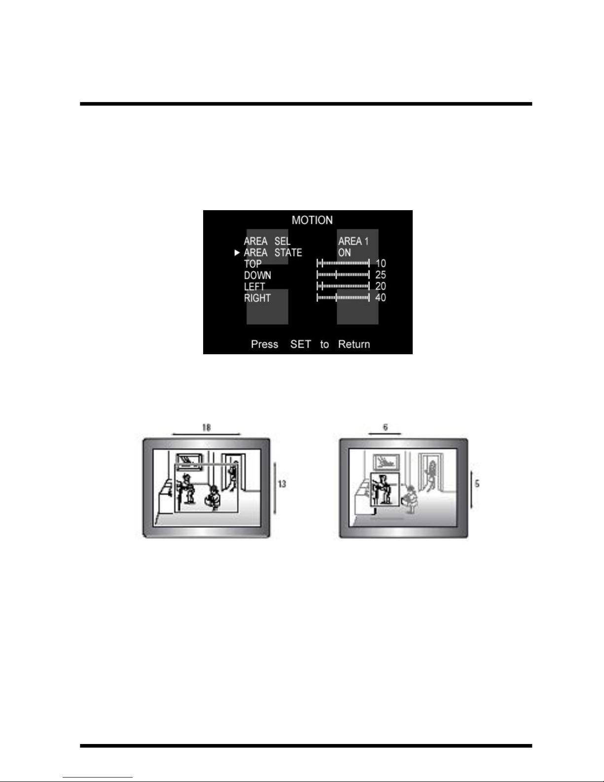
D) Whenever your camera detects motion, THE WORDS “motion
detected’ will appear on the screen.
▶OFF : Deactivation
▶ON : MOTION DET. Activated
- Press SET button.
- Move the arrow indicator to ‘AREA SET’ using UP and DOWN
button, and then press the SET button.
- Set the areas you want to observe.
29
Page 33
30
Max. Min.
Page 34
Operating your camera – PRIVACY
① Press the SET button to display the setup menu and move the arrow
indicator to ‘PRIVACY’ using the UP and DOWN button.
② SET ‘PRIVACY’ to the desired mode using the LEFT or RIGHT button.
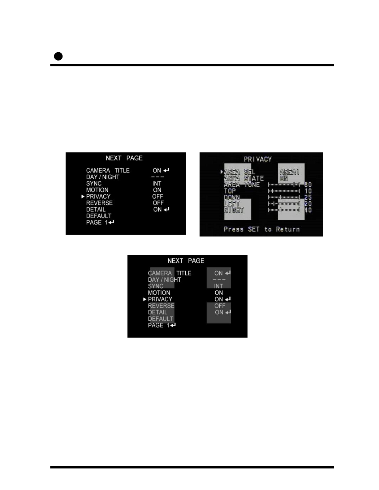
E) PRIVACY
To mask an area that you want to be private.
▶OFF : Deactivation
31
▶ON : PRIVACY mode activated
-Press the SET button.
-Move the arrow indicator to area you want to mask.
-Set ‘ON’ using LEFT or RIGHT button.
-Press the SET button and then set the area’s bounds
as for Motion detection
Page 35

Operating your camera – REVERSE
① Press the SET button to display the setup menu and move the arrow
indicator to ‘REVERSE’ using the UP and DOWN button.
② SET ‘REVERSE’ to the desired mode using the LEFT or RIGHT button.
F) REVERSE
32
▶OFF : Deactivation
▶ON : Reverse the image RIGHT or LEFT.
Page 36
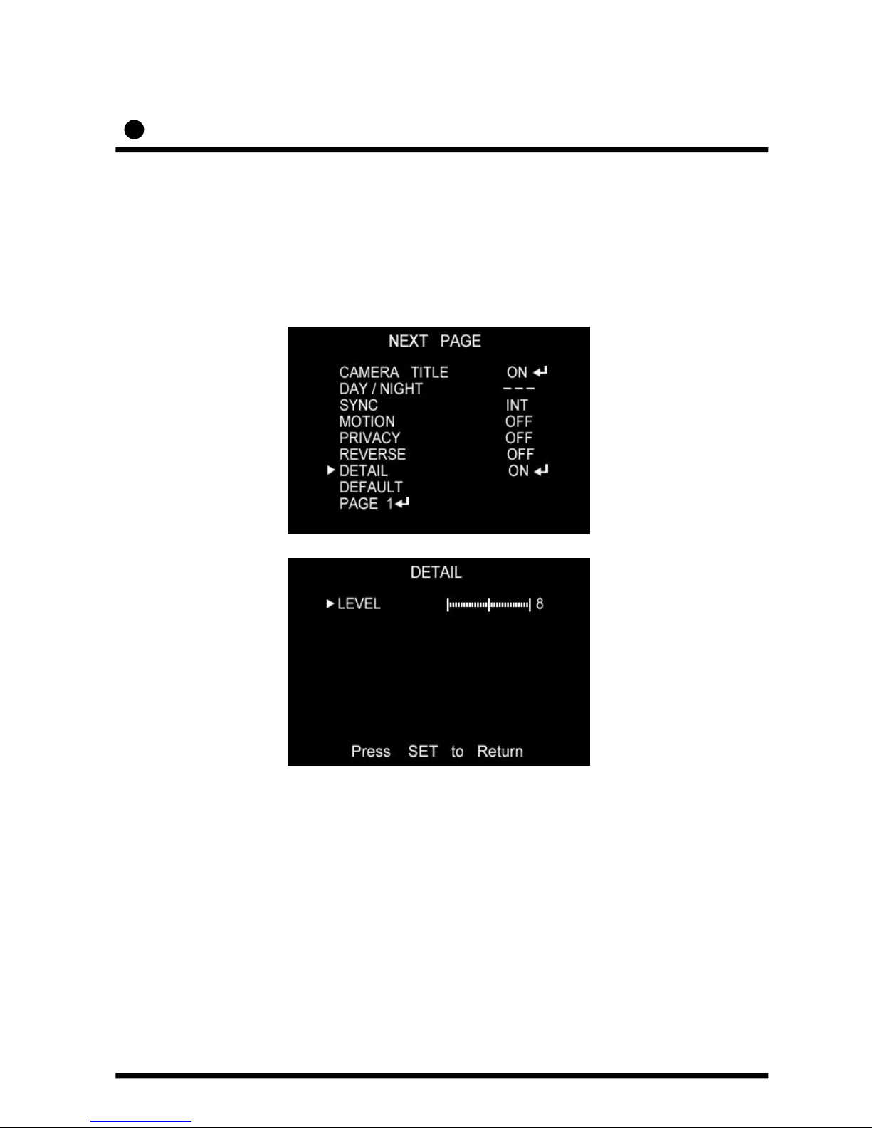
Operating your camera – DETAIL
① Press the SET button to display the setup menu and move the arrow
indicator to ‘DETAIL’ using the UP and DOWN button.
② SET ‘DETAIL’ to the desired mode using the LEFT or RIGHT button.
F) DETAIL
▶OFF : Deactivation
▶ON : DETAIL control mode (level 0~31)
When the level is up, the sharpness will increase.
Control this level to get your best picture quality.
If the level is too high, you can get an unnatural image
with video noise.
33
Page 37

Operating your camera – DEFAULT / PAGE 1
G) DEFAULT
: Use to reset your camera to FACTORY DEFAULT SETTING.
H) PAGE 1
: PAGE 1 : Save the setting of NEXT PAGE function, and then
move to SET UP menu.
34
Page 38

Troubleshooting
If you have trouble operating your camera, refer to the following table.
If the guidelines do not enable you to solve the problem, contact an
authorized technician.
Problem Solution
Nothing appears on
the screen.
● Check that the power cord and line connection
between the camera and monitor are fixed
properly.
● Check that you have properly connected VIDEO
cable the camera VIDEO output jack.
The image on the
screen is dim.
● Is lens stained with dirt? Clean your lens with soft,
clean cloth.
● Set the monitor to proper condition.
● If the camera is exposed to too strong light
change the camera position.
● Adjust the lens’ focus properly.
The image on the
screen is dark.
● Adjust the contrast feature of the monitor.
● If you have an intermediate device, set the
75Ω/Hi-z properly.
The camera is not
working properly, and
the surface of the
camera is not.
● Check that you have properly connected
the camera to an appropriate power source.
MOTION DETECTION
function is not active.
● Have you set ‘MOTION DET.’ menu to off?
● Have you set ‘MD LEVEL’ to too how?
● Have you set ‘MD ARAEA’ properly
35
Page 39

Problem Solution
The color of the
picture is not
matched.
● Check that you have properly set the ‘WHITE BAL’
menu
The image on the
screen flickers.
● Is the camera facing to direct sunlight or fluorescent
lighting? Change the camera option.
L/L mode isn’t able
to be selected.
● Have you connected your camera to DC power
source? Connect it to AC power source.
36
Page 40

SPECIFICATIONS
ITEM
HTINTB1
HTINTB2
Power Source DC 12V & AC 24v ( Dual Voltage )
Power Consumption 280mA(DC) / 3.8W(AC)
Image Sensor 1/3”, SONY SUPER HAD CCD, 410,000 pixels
Total Pixels 811(H) x 508(V) , 1/3” CCD
Effective Pixels 768(H) x 494(V) , 1/3” CCD
LENS TYPE
HTINTB1 : DC VARIFOCAL AUTO IRIS 3mm~9mm
HTINTB2 : DC VARIFOCAL AUTO IRIS 5mm~50mm
Maximum Aperture Ratio 1 : 1.3 ~2.0
Scanning System 2 : 1 Interlaced 525 Lines / 60 Fields / 30 Frames
Synchronization Internal / Line Lock selectable
Video Output 1.0V [p-p] NTSC Composite, 75Ω / BNC Connector
Resolution 530 TV Line
Gain Control AGC-L, AGC-H, OFF selectable
Electric Shutter Speed 1/60 ~ 1/200,000 sec
INTENSIFIER Built-in ( selectable limit ~ X128)
WHITE BALANCE ATW / AWC /MANUAL
Min. Illumination 0.003Lux (intensifier) 0.3Lux (sh)
S/N ( Y signal) 50dB (Weight On)
Reduction Noise OFF / LOW / MIDDLE / HIGH
Motion Detection MD1 / MD2 / OFF
On Screen Display ( O.S.D ) Built - in
PRIVACY Function ON / OFF (4 Programmable Zone)
Operational Temperature -10℃ ~ +50℃ (-14℉ ~122℉)
Operational Humidity 30% ~90% RH
37
Page 41

DIMENSIONS
82
156
92
190
* SIDE VIEW : HTINTB1
* SIDE VIEW : HTINTB2
Speco technologies
Speco technologies
38
Page 42

WARRANTY
39
Page 43

MEMO
Page 44

MEMO
Page 45

VER. 080501
This manual is based on the date as shown in the right and specifications are subject to
Change without notice for quality improvement.
200 New Highway
Amityville, NY 11701
631-957-8700
www.specotech.com
 Loading...