

Page 1

DVR-4TH/8TH/16TH Series
SPECO TECHNOLOGIES 01/09
®
1-800-645-5516
200 New Highway
Amityville, NY 11701
www.specotech.com
DVR-4TH
DVR-8TH
DVR-16TH
Digital Video Recorder Family
With Network/DDNS Video Server
User’s Manual
Page 2

User’s Manual
DVR-4TH/8TH/16TH Series
SPECO TECHNOLOGIES 01/09
1
Page 3
User’s Manual
DVR-4TH/8TH/16TH Series
SPECO TECHNOLOGIES 01/09
2
Caution and Preventive Tips
• Take care not to drop the unit or subject the unit to major shocks or jolts.
• Do not place this unit on an unstable stand, bracket or mount.
• This unit is designed for indoor use only. Do not place the unit near water or in other
extremely humid conditions.
• This unit should not be placed in a built-in installation unless proper ventilation is provided.
• Please check the type of power source available before you plug and operate the unit.
• If the clearing is necessary, note to plug the unit from the outlet before uncovering the top
cover. Do not use liquid cleaners or aerosol cleaners. Use only a damp cloth for cleaning.
• Always power down the system prior to connecting and disconnecting accessories, with
the exception of USB devices.
• Lithium battery: Danger of explosion if battery is incorrectly replaced. Replace with
the same type of battery or equivalent type recommended by the battery manufacturer.
Dispose of used batteries according to the battery manufacturer’s instructions.
This symbol intends to alert the user to the presence of important operating and
maintenance (servicing) instructions in the literature accompanying the
appliance.
This symbol intends to alert the user to the presence of unprotected “Dangerous
Voltage” within the product’s enclosure that may be strong enough to cause a
risk of electric shock.
Page 4

User’s Manual
DVR-4TH/8TH/16TH Series
SPECO TECHNOLOGIES 01/09
3
Important Information
Before proceeding, please read and observe all instructions and warnings in this
manual. Retain this manual with the original bill of sale for future reference and, if necessary,
warranty service. When unpacking your unit, check for missing or damaged items. If any item is
missing, or if damage is evident, DO NOT INSTALL OR OPERATE THIS PRODUCT. Contact your
dealer for assistance.
Rack Mounting
Consult with the supplier or manufacturer of your equipment rack for the proper procedure
and hardware for mounting this product in a safe fashion. Avoid uneven loading or
mechanical instability when rack-mounting units. Make sure the units are installed to get
enough airflow for safe operation. The maximum temperature for rack-mounted units is 104
°F/40 °C. Check product label for power supply requirements to assure that no overloading
of supply circuits or over current protection occurs. Main grounding must be reliable and
uncompromised by any connections.
Page 5

User’s Manual
DVR-4TH/8TH/16TH Series
SPECO TECHNOLOGIES 01/09
4
Table of Contents
1. Overview .....................................................................................................................13
1.1 Product Key Features ........................................................................................14
1.2 Product Application Diagram..............................................................................15
2. System Setup..............................................................................................................16
2.1 Position the Unit.................................................................................................16
2.2 Selecting Video Format......................................................................................16
2.3 Connecting Devices to the Unit..........................................................................16
2.4 Rear Panel Connections....................................................................................17
3. General System Setup ...............................................................................................20
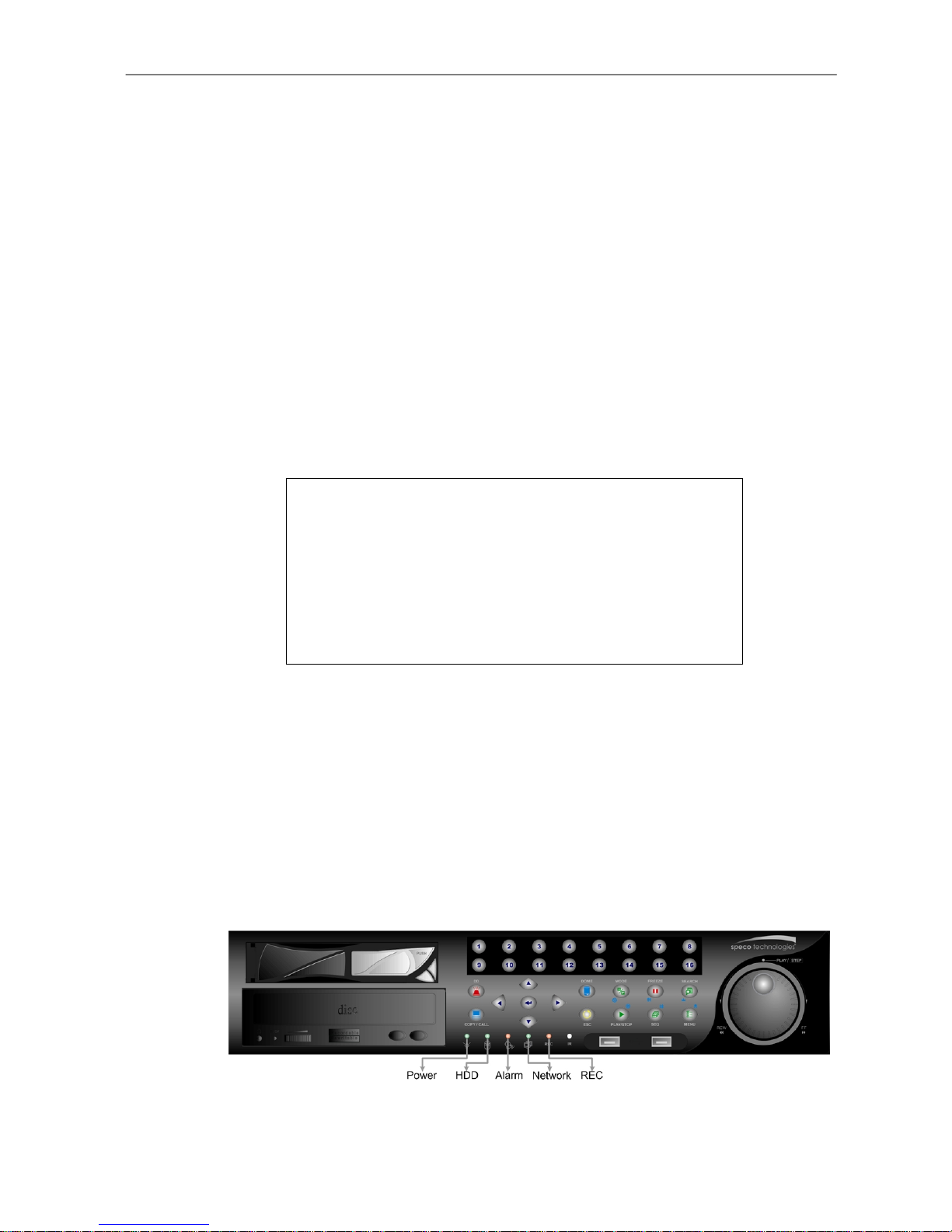
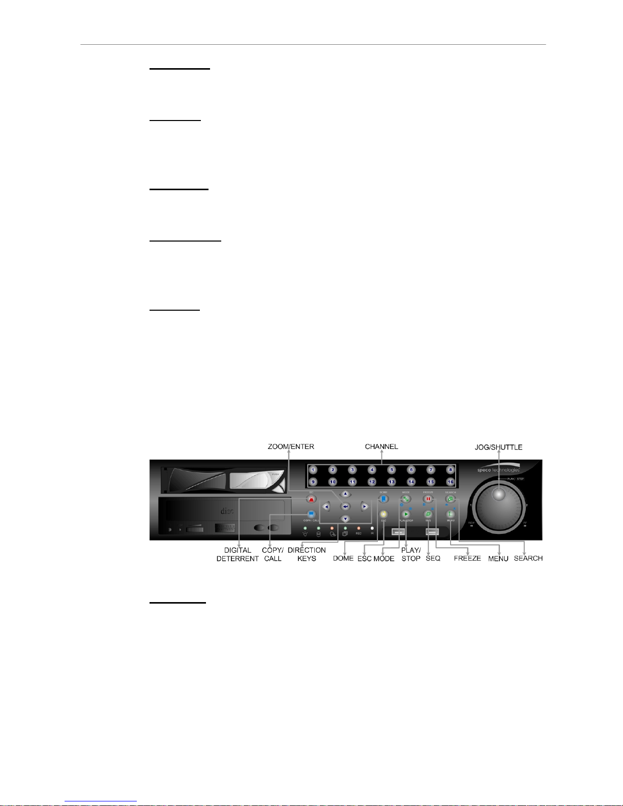
3.1 Front Panel Introduction ....................................................................................20
3.1.1 LED Definition.........................................................................................20
3.1.2 Functional Keys ......................................................................................21
3.2 Entering OSD Setup Menu ................................................................................24
3.2.1 User Management ..................................................................................25
3.3 Configuring the HDD in the unit .........................................................................26
3.4 Power On/ Off the Unit.......................................................................................27
3.5 System Date/ Time Setting ................................................................................28
3.5.1 Set Date/ Time ........................................................................................28
3.5.2 Daylight Saving Time Setup .................................................................29
3.5.3 Network Time Protocol Setup..................................................................30
3.6 IP Camera Setting .............................................................................................31
3.6.1 IP Camera Information ............................................................................31
3.6.2 Connection Setup ...................................................................................32
3.6.3 Device Setup...........................................................................................33
3.6.4 Activated .................................................................................................33
3.6.5 Status ......................................................................................................33
3.7 Record Schedule/ Quality Setting......................................................................34
3.7.1 Record Mode Setup ................................................................................34
3.7.2 Schedule Setup.......................................................................................34
Day/ Night Time Start ..............................................................................35
Day/ Night Time End...............................................................................35
Weekend Schedule.................................................................................35
Weekend Start/ End ................................................................................35
3.7.3 Preset Record Configuration...................................................................35
3.7.4 Per Camera Configuration ......................................................................36
3.7.5 Record Event Video Only........................................................................36
4. Basic Operation..........................................................................................................37
Page 6

User’s Manual
DVR-4TH/8TH/16TH Series
SPECO TECHNOLOGIES 01/09
5
4.1 Viewing Live/ Playback Video............................................................................37
4.1.1 Viewing Modes........................................................................................37
4.1.2 Digital Zoom............................................................................................38
4.1.3 Viewing Live Cameras ............................................................................38
To Freeze Live Image..............................................................................38
4.1.4 Viewing Recorded Video.........................................................................38
Key Usage in Playback ...........................................................................39
Pause Playback and Single Step Forward/ Backward ............................39
4.2 Sequence Setup ................................................................................................40
4.2.1 Sequence on Main Monitor .....................................................................40
4.2.2 Call Monitor Control ................................................................................40
4.3 Searching Recorded Video................................................................................41
4.3.1 Searching by Time ..................................................................................41
4.3.2 Searching by Event.................................................................................42
4.3.3 Search by Text ........................................................................................43
4.4 Video Export ......................................................................................................44
4.4.1 Export from OSD Setup Menu ................................................................44
4.4.1.1 Select the External Device......................................................45
4.4.1.2 Select Video for Exporting.......................................................45
4.4.1.3 Digital Signature......................................................................46
4.4.1.4 Erase Disc...............................................................................47
4.4.2 Quick Video Export through Front Panel.................................................47
4.4.2.1 ezBurn Introduction.................................................................47
4.4.2.2 Export Normal Video...............................................................48
4.4.2.3 Export Event Video .................................................................48
4.5 Deleting Recorded Video...................................................................................49
4.6 Dome Control.....................................................................................................50
4.6.1 Dome Connection ...................................................................................50
4.6.2 Dome Protocol Setup..............................................................................51
4.6.3 RS485 Setup...........................................................................................52
4.6.4 Dome Controlling Key .............................................................................53
4.6.5 Setting Preset Points...............................................................................54
4.6.6 Calling Preset Points...............................................................................55
4.7 2-Way Audio Talk Function ................................................................................56
4.8 UPnP Function...................................................................................................56
4.8.1 Setting Up the DVR and the PC..............................................................57
4.8.2 UPnP NAT Traversal Function ................................................................57
5.
Advanced System Configuration ..............................................................................58
Username and Password ...........................................................................................58
Key Usage in OSD setup menu..................................................................................59
Page 7

User’s Manual
DVR-4TH/8TH/16TH Series
SPECO TECHNOLOGIES 01/09
6
Key Usage in Virtual Keyboard...................................................................................60
5.1 System Setup ....................................................................................................61
5.1.1 System/Version Info ................................................................................61
5.1.1.1 DVR System Information & Version Numbers.........................61
5.1.1.2 Software Upgrade via Local Device ........................................62
5.1.1.3 Software Upgrade via Internet ................................................62
5.1.2 Language................................................................................................63
5.1.3 Date / Time..............................................................................................63
5.1.3.1 Date / Time Setting(s) .............................................................63
5.1.3.2 Time Zone...............................................................................64
5.1.3.3 Date / Time Display.................................................................64
5.1.3.4 Date Display Mode..................................................................64
5.1.3.5 Time Display Mode .................................................................65
5.1.3.6 Date/Time Order .....................................................................65
5.1.3.7 Daylight Saving Time Setup ....................................................65
Daylight Saving Time ..............................................................65
DST Start / End .......................................................................65
DST Bias.................................................................................65
5.1.3.8 Network Time Protocol Setup..................................................65
NTP Server .............................................................................66
Automatically Time Sync.........................................................66
Manually Time Sync................................................................66
5.1.4 Unit Name...............................................................................................66
5.1.5 Show Unit Name .....................................................................................67
5.1.6 User Management ..................................................................................67
5.1.6.1 Password Protection ...............................................................67
5.1.6.2 Account Setup.........................................................................67
5.1.6.3 Authority Setup .......................................................................68
5.1.6.4 Load Default Setting ...............................................................68
5.1.7 Network Setup ........................................................................................69
5.1.7.1 LAN Select ..............................................................................69
5.1.7.2 LAN Setup...............................................................................70
DHCP......................................................................................70
IP ............................................................................................70
Netmask..................................................................................71
Gateway..................................................................................71
DNS ........................................................................................71
PPPoE Account.......................................................................71
PPPoE Password....................................................................72
PPPoE Max Idle......................................................................72
Page 8

User’s Manual
DVR-4TH/8TH/16TH Series
SPECO TECHNOLOGIES 01/09
7
Connect At Booting .................................................................72
Network Restart ......................................................................73
5.1.7.3 Modem Setup..........................................................................73
Dial-in Setup ...........................................................................73
Dial-out Setup .........................................................................76
Dial Port Selection ..................................................................79
5.1.7.4 Trigger Port .............................................................................79
5.1.7.5 Email Address .........................................................................80
5.1.7.6 SMTP Setup............................................................................80
Email via SMTP ......................................................................80
SMTP Server ..........................................................................80
SMTP Port ..............................................................................81
SMTP Account ........................................................................81
SMTP Password .....................................................................82
5.1.7.7 DDNS Setup ...........................................................................82
Enable DDNS..........................................................................82
Host Name..............................................................................83
DDNS Port ..............................................................................83
Submit/ Update .......................................................................83
ezDDNS..................................................................................84
5.1.7.8 UPnP Setup ............................................................................84
UPnP ......................................................................................84
UPnP NAT Traversal ...............................................................84
5.1.8 RS485 Setup...........................................................................................85
5.1.8.1 Unit ID.....................................................................................85
5.1.8.2 Baud Rate...............................................................................85
5.1.8.3 Bits..........................................................................................85
5.1.8.4 Stop.........................................................................................85
5.1.8.5 Parity.......................................................................................85
5.1.9 Audio Output/ Key Beep..........................................................................85
5.1.9.1 Audio Output...........................................................................86
5.1.9.2 Key Beep ................................................................................86
5.1.10 IP Camera Support...............................................................................86
5.2 Monitor Setup ....................................................................................................87
5.2.1 Show Camera Title..................................................................................87
5.2.2 Title Position............................................................................................87
5.2.3 Monitor Brightness ..................................................................................88
5.2.4 Monitor Contrast .....................................................................................88
5.2.5 Monitor Chrominance..............................................................................88
5.2.6 Screen Center Adjust ..............................................................................88
Page 9

User’s Manual
DVR-4TH/8TH/16TH Series
SPECO TECHNOLOGIES 01/09
8
5.2.7 VGA Resolution.......................................................................................89
5.2.8 VGA Frequency.......................................................................................89
5.2.9 Show Color Bar.......................................................................................89
5.3 Camera Setup....................................................................................................90
5.3.1 Analog Camera .......................................................................................90
5.3.1.1 Camera Select ........................................................................90
5.3.1.2 Dome Protocol ........................................................................90
5.3.1.3 Dome ID..................................................................................90
5.3.1.4 Camera Title............................................................................91
5.3.1.5 Covert .....................................................................................91
5.3.1.6 Termination .............................................................................92
5.3.1.7 Brightness...............................................................................92
5.3.1.8 Contrast ..................................................................................92
5.3.1.9 Saturation ...............................................................................92
5.3.1.10 Hue .........................................................................................92
5.3.1.11 Audio Association....................................................................92
5.3.2 IP Camera...............................................................................................92
5.3.2.1 IP Camera Select ....................................................................93
5.3.2.2 IP Camera Title .......................................................................93
5.3.2.3 Hostname/IP ...........................................................................94
5.3.2.4 Model ......................................................................................94
5.3.2.5 Connection Setup ...................................................................94
Account...................................................................................94
Password ................................................................................94
Management Port ...................................................................94
Streaming Format ...................................................................94
Advance Streaming Option .....................................................95
Streaming Port ........................................................................95
Streaming Protocol..................................................................95
IP Dome Protocol....................................................................95
5.3.2.6 Device Setup...........................................................................95
Product ID...............................................................................96
Image Resolution/ FPS/ Compression/ Quality.......................96
Sharpness/ Brightness/ Contrast/ Saturation/Hue...................96
Apply.......................................................................................97
5.3.2.7 Activated .................................................................................97
5.3.2.8 Status ......................................................................................97
5.4 Record Setup.....................................................................................................98
5.4.1 Record Mode Setup ................................................................................98
5.4.1.1 Record Resolution ..................................................................98
Page 10

User’s Manual
DVR-4TH/8TH/16TH Series
SPECO TECHNOLOGIES 01/09
9
5.4.1.2 Record Format ........................................................................99
5.4.1.3 Max Rec. PPS.........................................................................99
5.4.2 Schedule Setup.......................................................................................99
5.4.2.1 Day / Night Time Start / End....................................................99
5.4.2.2 Weekend Schedule.................................................................99
5.4.2.3 Weekend Start / End .............................................................100
5.4.3 Preset Record Configuration.................................................................100
5.4.4 Per Camera Configuration ....................................................................100
5.4.4.1 Camera Select ......................................................................101
5.4.4.2 Normal PPS ..........................................................................101
5.4.4.3 Normal Qlty...........................................................................101
5.4.4.4 Event Max PPS.....................................................................101
5.4.4.5 Event Qlty .............................................................................101
5.4.4.6 Event Active ..........................................................................101
5.4.5 ezRecord Setup ....................................................................................102
5.4.6 Data Lifetime.........................................................................................103
5.4.7 Pre-Alarm Recording ............................................................................103
5.4.8 Circular Recording ................................................................................104
5.4.9 Audio Recording ...................................................................................104
5.4.10 Purge Data............................................................................................104
5.4.10.1 Purge All Data .......................................................................104
5.4.10.2 Purge All Event Data.............................................................104
5.4.10.3 Purge Event Before...............................................................105
5.4.10.4 Start To Purge .......................................................................105
5.5 Sequence Setup ..............................................................................................105
5.5.1 Main / Call Monitor Dwell ......................................................................105
5.5.2 Main / Call Monitor Schedule ................................................................105
5.6 Event Setup .....................................................................................................106
5.6.1 Internal Buzzer......................................................................................106
5.6.2 Event Icon.............................................................................................106
5.6.3 Email Notice..........................................................................................107
5.6.4 Email Attachment ..................................................................................107
5.6.5 Alert Notification Setup..........................................................................107
5.6.5.1 Alert Configuration Set..........................................................108
5.6.5.2 Alert Configuration ................................................................108
5.6.5.3 Alert IP ..................................................................................108
5.6.5.4 Alert Port...............................................................................108
5.6.5.5 Alert Interval..........................................................................108
5.6.6 Event Full Screen..................................................................................108
5.6.7 Event Duration ......................................................................................109
Page 11

User’s Manual
DVR-4TH/8TH/16TH Series
SPECO TECHNOLOGIES 01/09
10
5.6.8 Per Channel Config...............................................................................109
5.6.8.1 Channel Select......................................................................109
5.6.8.2 Video Loss Detect.................................................................109
5.6.8.3 Motion Detect........................................................................109
5.6.8.4 Detection Config ...................................................................110
Detected Area Setup ............................................................. 110
Sensitivity.............................................................................. 110
Area Threshold ..................................................................... 111
5.6.8.5 Alarm In ................................................................................ 111
5.6.8.6 Alarm Out.............................................................................. 111
5.6.8.7 Digital Deterrent – Day/ Night/ Weekend ..............................112
5.7 Database Setup ...............................................................................................114
5.7.1 Total / Free Size of HDD .......................................................................114
5.7.2 Avail. Rec Time ..................................................................................... 114
5.7.3 Internal / External Disks ........................................................................ 115
5.7.4 NAS Device........................................................................................... 116
5.8 Configuration ...................................................................................................117
5.8.1 Load Factory Default............................................................................. 117
5.8.2 Import Configuration .............................................................................117
5.8.3 Export Configuration ............................................................................. 118
5.8.3.1 Copy Destination................................................................... 118
5.8.3.2 Configuration Name .............................................................. 118
5.8.3.3 Begin Export .........................................................................118
5.8.4 Import Deterrent.................................................................................... 119
5.8.5 Export Deterrent.................................................................................... 119
5.9 Video Export .................................................................................................... 119
5.9.1 Select Device........................................................................................120
5.9.2 Select Channel......................................................................................121
5.9.3 From / To Time ......................................................................................121
5.9.4 Select Events........................................................................................121
5.9.5 Data Type..............................................................................................121
5.9.6 Digital Signature....................................................................................122
5.9.7 Erase Disc.............................................................................................122
5.9.8 Begin Export .........................................................................................122
5.10 Text Setup........................................................................................................123
5.10.1 Text Function.......................................................................................123
5.10.2 Text Overlay ........................................................................................123
5.10.3 Exception Text Setup...........................................................................124
5.10.3.1 Exception No.........................................................................124
5.10.3.2 Trigger...................................................................................124
Page 12

User’s Manual
DVR-4TH/8TH/16TH Series
SPECO TECHNOLOGIES 01/09
11
5.10.3.3 Exception String....................................................................124
5.10.3.4 By Numerals .........................................................................124
5.10.4 Input Setup..........................................................................................125
5.10.4.1 Port Selection........................................................................125
5.10.4.2 Input source ..........................................................................126
5.10.4.3 Camera Selection .................................................................126
5.10.4.4 Text Filter ..............................................................................126
5.10.4.5 Manual Filter Setup...............................................................126
5.10.4.6 Input Process........................................................................127
5.10.4.7 Text Baud Rate .....................................................................127
5.10.4.8 Text Bit ..................................................................................127
5.10.4.9 Text Stop ...............................................................................127
5.10.4.10 Text Parity .............................................................................127
5.11 Shutdown.........................................................................................................128
6. Remote Monitoring Software...................................................................................129
6.1 Remote Monitoring System Requirements ......................................................129
6.2 Software Installation.........................................................................................130
6.2.1 Change Internet Settings ......................................................................130
6.2.2 Install Remote Monitoring Software ......................................................132
6.2.2.1 Log in / Log off ......................................................................133
6.2.2.2 Software Upgrades ...............................................................134
6.3 Basic Operation for Remote Monitor................................................................134
6.3.1 View Live Video.....................................................................................134
6.3.1.1 Select Display Mode .............................................................135
6.3.1.2 Operate Cameras with Dome Control ...................................135
6.3.2 Instant Recording..................................................................................136
6.3.2.1 Record Video Instantly..........................................................136
6.3.2.2 Playback Instant Recorded Video .........................................136
6.3.3 Playback Video .....................................................................................137
6.3.3.1 Playback Remote Video........................................................137
6.3.3.2 Playback Local *.drv Files.....................................................138
6.3.3.3 Playback Controls .................................................................138
6.3.4 Verify Digital Signature..........................................................................139
6.3.5 Search from Event List..........................................................................139
6.3.6 Take a Snapshot ...................................................................................139
6.3.7 Remote Monitoring Software Trouble Shooting Guide ..........................140
Appendix A: Technical Specifications .........................................................................141
Appendix B: Preset Record Configuration ..................................................................143
Appendix C: Record Duration.......................................................................................145
Appendix D: Dial-up Connections via Modem ............................................................147
Page 13

User’s Manual
DVR-4TH/8TH/16TH Series
SPECO TECHNOLOGIES 01/09
12
Establishing Dial-in Connection ................................................................................147
Establishing Dial-out Connection..............................................................................151
Appendix E: Verifying Digital Signature ......................................................................156
Appendix F: Alarm I/O Pin Definition ...........................................................................159
Appendix G: HDD PC Player Tool Introduction...........................................................161
Using EXT2IFS on Your PC......................................................................................161
Start Playing the *.drv file..........................................................................................163
Appendix H: IR Remote.................................................................................................165
Appendix I: ezRecord Diagram Sample .......................................................................167
Appendix J: Connect to External Storage Device.......................................................170
Page 14
User’s Manual
DVR-4TH/8TH/16TH Series
SPECO TECHNOLOGIES 01/09
13
1. Overview
The DVR-4TH/ 8TH/ 16TH series unit is an integrated digital video recorder
that combines the features of a time-lapse audio / video recorder, a
multiplexer, and a video server to create a single security CCTV solution.
Its outstanding pentaplex operation enables users to view live or playback
recorded video, have remote access through network simultaneously while
recording other video, and to view previously recorded video instantly by
entering the time and date or selecting recorded video from the event list.
The DVR-4TH/ 8TH/ 16TH series unit is enhanced to provide Multi-Codec
including H.264, MPEG-4, and MJPEG compression mode. Moreover, its
distinctive hybrid solution supports the coexistence of network compatible IP
devices and convenient analog connections.
The DVR-4TH/ 8TH/ 16TH series includes SpecoRemote™, the remote
viewing and configuration software that is a Web-browser plug-in, which
allows users to view live, or recorded video images, and enables remote
configuration. The remote software is stored in the DVR-4TH/ 8TH/ 16TH
series unit and deployed over a LAN, WAN or Internet connection to remote
Windows-based computers. This simplifies the installation and maintenance
of the software components so all remote users are kept up to date.
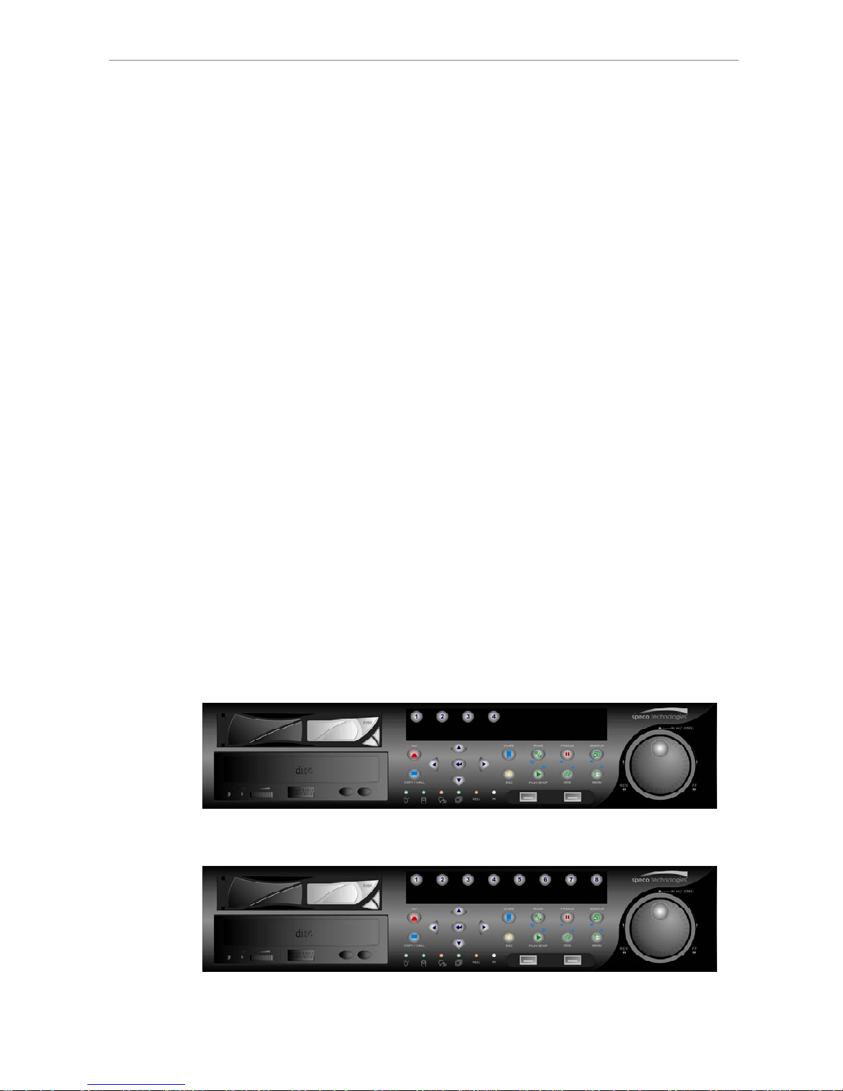
Please refer to the following for the front panel design of the three models.
DVR-4TH
DVR-8TH
Page 15

User’s Manual
DVR-4TH/8TH/16TH Series
SPECO TECHNOLOGIES 01/09
14
DVR-16TH
1.1 Product Key Features
The DVR-4TH/ 8TH/ 16TH series offers advanced features not typically found
in standard multiplexers. It integrates the full features of a DVR, a multiplexer
and a video server (by using the software SpecoRemote™). The key features
of the DVR-4TH/ 8TH/ 16TH series are listed as follows.
Advanced Functions
• H.264 high quality compression
• 4/8/16 channels for video input
• Pentaplex operation enables simultaneous Live/ Playback monitor and
remote access via network, while recording without interruption
• SpecoRemote™ web-based software for remote monitoring and control
via LAN or Internet including CMS
• Embedded Linux operating system
• Real-time “live display” for each channel
• Recording frame rate up to 120 pps(NTSC)/ 100 pps(PAL)
• 16 Channels of audio recording/ playback
• Digital Deterrent
• Two-way audio
• 4 USB2.0 ports for video clip export and/or backup
• Easy software upgrade via USB ThumbDrive
®
, DVD+RW or Internet
Remote Application
• Up to 4 internal hard drives (4
th
drive requires removal of the DVD-RW)
• Supports SATA HDDs up to 1TB
• POS Support
• Gigabit LAN (RJ45) for external storage and NAS for TH series models
• 2X Digital Zoom available in Live and Playback mode
• Automatic camera detection (Plug & Play)
Page 16
User’s Manual
DVR-4TH/8TH/16TH Series
SPECO TECHNOLOGIES 01/09
15
• Covert camera operation provides enhanced security and administrator
control
• Per camera configuration for camera settings, frame rate, picture bit rate,
alarms, motion detection.
• Programmable day/ night/ weekend scheduling
• Programmable main monitor/ call-monitor switching sequence
• Powerful alarm processor allows flexible alarm trigger and responses,
including alarm, motion, and camera failure
• Dome control protocols: Speco, Pelco D, Pelco P, Fastrax 2, AD422,
Panasonic_C, Panasonic_N, DSCP and JVC
• 8 levels of password security
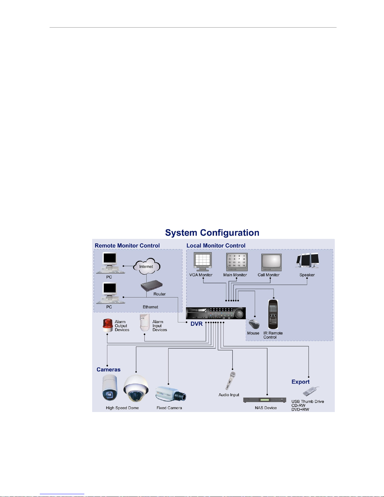
1.2 Product Application Diagram
According to system demand, connect the unit with selective devices as
shown in the system diagram below to complete a video surveillance solution.
The figure also displays the expandability and flexibility of this digital
recording system.
Page 17

User’s Manual
DVR-4TH/8TH/16TH Series
SPECO TECHNOLOGIES 01/09
16
2. System Setup
Prior notices and an introduction on system installation will be described in
this chapter. Please follow the instructions to operate the unit.
In order to prevent the unit from data loss or system damage that might result
from a sudden power fluctuation, the use of an Uninterruptible Power Supply
(UPS) is highly recommended.
2.1 Position the Unit
Position/ mount the DVR-4TH/ 8TH/ 16TH series unit in an appropriate,
steady location and make sure the power is off before making any
connections. The area should avoid hindering or blocking the unit from airflow.
Sufficient airflow is required to protect the unit from overheating. The
tolerable high temperature of the operating environment is 104°F/ 40°C.
The unit utilizes heat-conducting techniques to transfer internal heat to the
case, especially to the bottom side of the unit.
NOTE: Be sure not to remove the rubber feet, and always leave a
space for air ventilation on the bottom side of the unit.
2.2 Selecting Video Format
The DVR-4TH/ 8TH/ 16TH series unit is designed to operate under either
NTSC or PAL video formats. Please contact a qualified service person to
perform the installation procedure.
2.3 Connecting Devices to the Unit
This section lists some important notices that should be read BEFORE
making any connections to the DVR-4TH/ 8TH/ 16TH series unit.
NOTE: Be sure to connect short-term external devices, such as USB
ThumbDrive
®
, USB DVD+RW, USB Hard Disk Drive, etc., ONLY
AFTER the unit is successfully powered on.
Page 18
User’s Manual
DVR-4TH/8TH/16TH Series
SPECO TECHNOLOGIES 01/09
17
Connecting Required Devices
Before powering up, you should connect cameras and a main monitor to the
unit for basic operation. If needed, connect a call monitor for displaying full
screen video of all installed cameras in sequence.
Connecting Short-term Device
If you plan to install any short-term external devices, such as USB DVD+RW,
USB Hard Disk Drive, etc, to the DVR-4TH/ 8TH/ 16TH series and want to
use them as part of the unit system, make sure those devices are
connected only after the DVR-4TH/ 8TH/ 16TH is powered up. The
DVR-4TH/ 8TH/ 16TH series unit can only recognize the external devices
after the power-up process is completed.
2.4 Rear Panel Connections
There are several connectors on the rear panel of the DVR-4TH/ 8TH/ 16TH
series unit available for installations. The following figure shows the
connectors by name and a detailed description of each connector follows.
There are two differences on the rear panels of different models:
1. The BNC channel connectors are provided according to the supported
number of channels, respectively 4-ch, 8-ch, and 16-ch.
2. The terminal blocks of audio in/out and alarm I/O for DVR-4TH/ 8TH is
smaller whereas the terminal blocks of audio in/out and alarm I/O for
DVR-16TH is larger.
The detail description of each connector is as the following.
Page 19

User’s Manual
DVR-4TH/8TH/16TH Series
SPECO TECHNOLOGIES 01/09
18
Main Monitor (S-Video/ BNC/ VGA)
S-Video, BNC, and VGA output connectors are available for connecting to a
main monitor. The main monitor displays live image and playback recorded
video in full-screen or multiple window format.
Call Monitor (BNC)
The call monitor is used to display full screen video of all installed cameras in
sequence. The BNC call monitor connector allows the user to connect an
optional call monitor to the DVR-4TH/ 8TH/ 16TH series unit. Reference to
dual monitor support in section Dual Main Output.
Video Input
A group of BNC connectors is provided for video input streams from installed
cameras. The number of connectors equals to the number of channels. The
DVR-4TH/ 8TH/ 16TH series unit has 4/ 8/ 16 BNC connectors on the rear
panel, respectively.
Video Looping
The other group of BNC connectors positioned on the rear panel is for looping
out video input.
RS-232C
The unit provides a RS-232C communication port for sending and receiving
signals.
Alarm I/O & RS-485 Ports
The unit provides Alarm I/O and RS-485 ports that offer users the flexibility
required to connect the unit to other devices.
Refer to appendix Alarm I/O Pin Definition
for detailed pin definition on the
Alarm I/O for the DVR-4TH/ 8TH/ 16TH series unit.
NAS
The DVR-4TH/ 8TH/ 16TH series unit can connect to a Network Attached
Storage (NAS) device through this connector to increase storage space and
allow vast recording.
Page 20

User’s Manual
DVR-4TH/8TH/16TH Series
SPECO TECHNOLOGIES 01/09
19
Audio In
The DVR-4TH/ 8TH/ 16TH series unit provides 4/ 8/ 16 channels of audio
recording accordingly. The Audio In connectors are offered for connecting
audio source devices (e.g. external amplified microphone) to the unit. The
PIN of upper row is for input of each channel while the lower row is for
ground.
Main Audio Out
One RCA connector is provided for audio output of main monitor.
Audio Out
In addition to the RCA connector, the DVR-4TH/ 8TH/ 16TH series unit
provides 4/ 8/ 16 channels of audio exporting accordingly. The Audio Out
connectors are provided for connecting audio output devices (e.g. amplified
speakers) to the unit. The PIN of upper row is for output of each channel while
the lower row is for ground.
USB 2.0 (x4)
There are two USB 2.0 ports on the rear panel and two on the front panel to
allow users to connect external USB devices to the unit, such as a
ThumbDrive®, DVD+RW, or a USB mouse.
The DVR-4TH/ 8TH/ 16TH series unit allows users to preset the OSD settings
using a USB mouse or a USB keyboard.
LAN (RJ-45)
The DVR-4TH/ 8TH/ 16TH series unit is capable of networking. Once the unit
is connected to the LAN network, the users can remotely access the unit
through SpecoRemote™ on a PC.
Power Switch
The power switch is used to power up or shut down the unit.
Power Supply
Connect the power supply cord shipped with the unit to the power supply jack
to provide power to operate the DVR-4TH/ 8TH/ 16TH series unit.
NOTE: Use of other power supply cord may cause overloading.
Page 21
User’s Manual
DVR-4TH/8TH/16TH Series
SPECO TECHNOLOGIES 01/09
20
3. General System Setup
Before operating the DVR-4TH/ 8TH/ 16TH series unit, some general
configuration should be setup in advance. The following subsections will
introduce functional keys on the front panel and general configuration of the
DVR-4TH/ 8TH/ 16TH series unit.
The regularly displayed OSD information and its positions are shown in the
following figure. The title of the channel is displayed on the upper left-hand
corner of the window, either in full screen mode or in multiple-channel mode.
The current operating mode, including Call mode, Dome Control mode,
Playback mode, Freeze mode and Sequence mode, is displayed on the lower
left-hand corner of the screen. The date/ time information is displayed on the
lower right-hand corner of the screen.
Ch1
►*1
2008/10/22 PM 04:31:55
3.1 Front Panel Introduction
The functional keys on the unit’s front panel enable users to control the unit
and preset programmable settings.
3.1.1 LED Definition
The LED indication lights of the DVR-4TH/ 8TH/ 16TH series unit on the front
panel are described as follows.
Page 22
User’s Manual
DVR-4TH/8TH/16TH Series
SPECO TECHNOLOGIES 01/09
21
Power LED
The LED should be lit when the power is connected.
HDD LED
The LED will be lit while the HDD is processing data to or from the connected
HDD(s).
Alarm LED
The LED should be lit when an alarm is triggered.
Network LED
The LED should be lit when the DVR-4TH/ 8TH/ 16TH series unit is
connected to a network and it should blink when any data is being transferred.
REC LED
The LED should blink while the DVR-4TH/ 8TH/ 16TH series unit is recording.
3.1.2 Functional Keys
The DVR-4TH/ 8TH/ 16TH series unit’s function keys on the front panel are
described below for normal operation.
CHANNEL
• In both Live and Playback modes, press any CHANNEL key to view the
corresponding video in full screen. The number of the CHANNEL keys
corresponds to the number of cameras supported by the unit.
• In Dome Control mode, the key “1” is used to access the Set/ Go Preset
menu while the key “2” is used to hide or display the dome camera setting
parameters.
• In OSD virtual keyboard, press keys 1~9 to input number 1~9, and press
key 10 to input number 0.
Page 23

User’s Manual
DVR-4TH/8TH/16TH Series
SPECO TECHNOLOGIES 01/09
22
Digital Deterrent
Users can trigger warning announcement at certain camera site by pressing
the specific camera key and the digital deterrent key. Refer to section Digital
Deterrent for more detail about the setting of digital deterrent function.
COPY/ CALL
• In Live mode, press this button to enter call monitor control mode.
• In Dome Control mode, press CALL in association with ENTER to enter
the OSD setup menu of the dome camera.
• This is used to quick export video to an external device, such as USB
DVD+RW, USB ThumbDrive®, etc. For more detailed operating
instructions, refer to section Quick Video Export through Front Panel.
• In OSD virtual keyboard, press this key to input a period mark “.”.
Direction Keys
• In Zoom mode, these keys function as normal Direction Keys.
• In the OSD setup menu, the Direction Keys are used to move the cursor to
previous or next fields. To change the value in the selected field, press UP
/ DOWN keys.
ZOOM/ ENTER
• In OSD setup menu or selection interface, press this key to make selection
or to save settings.
• In live full screen viewing mode, press this key to view a 2× zoom image.
Press it again to return.
ESC
• Press to cancel or exit from certain mode or OSD setup menu without
changing the settings made previously.
• If the password protection has been enabled, press ESC for five seconds
to lock up the function of certain keys, including PLAY, MENU, SEARCH,
and DOME. Once users lock up the function of these keys, enter proper
username and password to gain access of the functions of these keys.
NOTE: Please go to the <System Setup> Æ <User Management>
menu to enable or disable the password protection.
Page 24

User’s Manual
DVR-4TH/8TH/16TH Series
SPECO TECHNOLOGIES 01/09
23
DOME
• Press this key to enter Dome Control mode. Please refer to section Dome
Control for more details about dome camera controlling operation.
• In OSD virtual keyboard, press this key to go backspace.
MODE
Press repeatedly to select desired main monitor display format. There are
four viewing modes available: full screen, 4-window (2×2), 9-window (3×3),
and 16-window (4×4). Refer to section Viewing Modes for more detailed
information.
PLAY/ STOP
Press this key to switch between live image and playback video.
NOTE: Video taken within the latest 5 ~ 10 minutes cannot be played
back because the video is still saved in the buffer.
SEQ (Sequence)
Press to start automatic sequencing of the video coming in from the installed
cameras.
FREEZE
• Press FREEZE while viewing live image, the live image will be frozen, but
the date/ time information shown on the monitor will continue updating.
The recording of the video will continue as well. Press FREEZE again to
return to live mode.
• Press FREEZE while playing recorded video, the playback video will be
paused. Press LEFT/ RIGHT to move the recorded video reverse/ forward
by a single step. Press FREEZE again to continue playing video.
MENU
Press this key to access the OSD setup menu.
SEARCH
In both Playback and Live mode, press SEARCH to access the Search menu
to search and playback recorded video by date/ time, events, or text.
Page 25

User’s Manual
DVR-4TH/8TH/16TH Series
SPECO TECHNOLOGIES 01/09
24
JOG/ SHUTTLE
• The jog/ shuttle knob is a dual function knob, including a shuttle ring and
an embedded jog disk, that provides wide range in playback control. Note
that the jog/ shuttle knob is active only when the unit is in Playback mode.
• When playing back videos, the shuttle ring can control playback speed in
either forward or backward directions. Rotate the shuttle ring clockwise/
counterclockwise to fast forward/ reverse playing speed. According to the
angle of rotation, the playing speed changes to 1×, 2×, 4×, 8×, 16×, or 32×,
in both forward and reverse playback.
• When the video is paused, the embedded jog disk can control single-step
playback. Clockwise rotation moves the video image one-step forward,
whereas counterclockwise rotation moves the video image one-step
backward. Note that single-step playback is for JPEG recoding only.
3.2 Entering OSD Setup Menu
The OSD setup menu is a hierarchical list of items for configuring the
DVR-4TH/ 8TH/ 16TH series unit. Collaborating with a USB mouse, setting up
the DVR can be easy as operating on a PC. Press MENU and input a valid
username. There are two preset accounts: “admin” and “user”. “admin” can
be inputted via pressing the hot key MENU, while “user” can be inputted via
pressing the hot key SEARCH. Move to <OK> and press ENTER to proceed.
Input Username
A B C D E F G H I J K L M
N O P QRSTUVWXYZ
a b c d e f g h i j k l m
n o p q r s t u v w x y z
0 1 2 3 4 5 6 7 8 9
.
!@
# − _ , “ + = *
◄ ► Backspace Delete
Cancel OK
The next step is to enter a corresponding password. The preset password for
“admin” is “1234”.
Password Verification
____________
Press Channel Keys To Enter Password
(4-8 Digits)
Press ◄ Key To Delete
Page 26
User’s Manual
DVR-4TH/8TH/16TH Series
SPECO TECHNOLOGIES 01/09
25
NOTE: It is strongly suggested to change the preset password to
prevent unauthorized access to the unit.
An icon displayed at the center-bottom of the screen will show the authority
level of the account. Under logout condition, the icon will show “N”. When an
account is logged in, its authority level number (1~8) will be shown.
Before completely logout, other functions can also be accessed without
having to login again. There are two ways to logout: manually logout by
pressing ESC key at Live mode, or auto logout when keys are not pressed for
5 minutes at Live/ Menu mode.
3.2.1 User Management
The DVR-4TH/ 8TH/ 16TH series unit provides the option to create up to
seven sets of usernames and passwords with customized authority, excluding
the preset “admin” account. From the Main Menu, select <System Setup> Æ
<User Management> and the menu is as the following:
User Management
1. Password Protection
2. Account Setup
3. Authority Setup
4. Load Default Setting
ON
No
Password Protection
Select <ON> to request for username and password for accessing functions
listed in Authority Setup menu, or select <OFF> to allow free access.
Account Setup
Setup customized username, password, and authority level in this menu. The
username is case sensitive. The authority level rank from level 1~8, and level
8 has highest authority. Alternatively, select <Disable> to stop using the
account.
NOTE: The username and authority level of the preset “admin”
account cannot be changed.
Page 27

User’s Manual
DVR-4TH/8TH/16TH Series
SPECO TECHNOLOGIES 01/09
26
Authority Setup
Setup the allowed authority level for accessing the functions listed in this
menu. The functions include: Playback/Search, Dome Control, Call Control,
Export Data, Menu Access, System Setup, Monitor Setup, Camera Setup,
Record Setup, Sequence Setup, Event Setup, Database Setup, Configuration,
Text Setup, and Shutdown. The authority level rank from level 1~8, and level
8 has highest authority. Alternatively, select <Disable> to allow free access.
NOTE: The “Menu Access” cannot be set to <Disable>.
When the account does not have authority to access certain functions, an
error message will be displayed on the screen.
Load Default Setting
Select <Yes> to load the default setting.
3.3 Configuring the HDD in the unit
There is an empty cartridge positioned on the front panel where users can
install a swappable HDD. There are two possible situations after a HDD is
installed into the unit.
• If a brand new HDD is installed, the unit will automatically format it and add
it into the database.
• If a used HDD that has a different data format is installed, the screen will
show “1 disk(s) with wrong data format! Please format then add to the
database manually”. Please follow the steps described below:
- Enter the OSD setup menu using account with appropriate privilege
and access <Database Setup>.
- Access <External Disks>.
- Find the HDD that was just installed, and select <Format> to format it.
- After the HDD is formatted, select <Add> to add it into the database.
Some recommended HDDs are listed as below:
SV35.2 160G / 320G
Barracuda ES.2 500G Seagate
Barracuda 7200.11 1000G
Hitachi
DeskStar 320G
Maxtor
DiamondMax 22 500G
Western Digital
WD AV 160G / 320G / 500G
Page 28
User’s Manual
DVR-4TH/8TH/16TH Series
SPECO TECHNOLOGIES 01/09
27
3.4 Power On/ Off the Unit
If the DVR-4TH/ 8TH/ 16TH series unit must be shutdown for any reason,
always remember to follow proper shutdown and power on procedures in
order to avoid damage to the unit.
To Power On the Unit
First check if the type of power source available is compatible before plugging
into the unit. Then turn on the unit using the power switch on the rear panel.
The system checking information and color bar will be shown on the monitor.
It will disappear when the unit has been properly powered on.
To Restart/ Shutdown the Unit
Press MENU and input the username and password that has sufficient
authority to access the OSD setup menu. Select <Shutdown> in Main menu
and press ENTER to enter the Shutdown menu, which displays as follows.
Shutdown
1. Power Off
2. Reboot
Execute
Execute
<Power Off>
Select this item to shutdown the unit. DO NOT disconnect the power during
shutdown until the message “You can safely turn off DVR now!” displays.
<Reboot>
Select this item to restart the unit. The system checking information and color
bar will be displayed on the monitor until the unit is properly restarted.
NOTE: While the DVR-4TH/ 8TH/ 16TH series unit is shutting down or
rebooting, the recoding and playback of videos will stop to avoid
abnormal images.
Page 29

User’s Manual
DVR-4TH/8TH/16TH Series
SPECO TECHNOLOGIES 01/09
28
3.5 System Date/ Time Setting
The user can set the current date, time and other OSD parameters in the
Date/ Time menu. The login account should have authority to access the
System Setup menu. In the OSD Main menu, select <System Setup> and
press ENTER, then select <Date/ Time> to access the Date/ Time menu; the
menu displays as follows.
Date/Time
1. Date
2. Time
3. Time Zone
4. Date/Time Display
5. Date Display Mode
6. Time Display Mode
7. Date/Time Order
8. Daylight Saving Time Setup
9. Network Time Protocol Setup
2008/02/21
PM10:39:26
OFF
1 Row
Y/M/D
24 HR
Date First
3.5.1 Set Date/ Time
Set Date/ Time
Select <Date>/ <Time> and press ENTER to adjust the settings. LEFT/
RIGHT keys are used to move the cursor to previous or next field, ENTER is
for selecting, and UP/ DOWN are used to change the value in the selected
field.
NOTE: The reset date/ time setting applies for recording new video,
the date and time of previously recorded video will not be changed.
NOTE: To avoid record database corruption, after changing the date/
time setting, it is recommended to clear the database.
Date/ Time Display
Users are allowed to choose to set the date/ time OSD displays in 1 or 2 rows.
Use the UP/ DOWN keys to change the setting. The default is to display the
date/ time OSD in one row.
Date Display Mode
This function allows user to set the OSD display type of the date/ time. There
are three options to select from: <Y/M/D>, <M/D/Y> or <D/M/Y>. “Y”
represents “Year”, “M” represents “Month” and “D” represents “Day”.
Page 30
User’s Manual
DVR-4TH/8TH/16TH Series
SPECO TECHNOLOGIES 01/09
29
Move to the desired item and press ENTER, the option starts blinking. Use
UP / DOWN keys to change the setting. The default setting is <Y/M/D> in
both NTSC/ PAL formats.
Time Display Mode
The user can choose to set the time format to <12 hour> or <24 hour>. Use
the UP/ DOWN keys to change the format. The default setting is <12 hour>.
Date/ Time Order
This item is used to set the order of the date/ time display to <Date First> or
<Time First>. Use UP/ DOWN keys to change the setting.
3.5.2 Daylight Saving Time Setup
The items in this sub-menu are for those people whom live in certain regions
to observe Daylight Saving Time.
Daylight Saving Time
Select <ON> to enable, or <OFF> to disable the function.
If the function is disabled, the DST Start/ End time and DST Bias will be
grayed out and cannot be accessed.
NOTE: If this function is enabled, the date/ time information will be
shown on the screen with a DST icon when playing back recorded
video or searching video in the event list. “S” indicates summer time
and “W” indicates wintertime.
DST Start/ End
This is used to program the daylight saving duration. Use Direction keys to
move the cursor to the next or previous field, use UP/ DOWN to change the
settings in the selected field.
DST Bias
<DST Bias> allows the user to set the amount of time to move forward from
the standard time for daylight saving time. The available options are <30>,
<60>, <90> and <120> minutes.
Page 31

User’s Manual
DVR-4TH/8TH/16TH Series
SPECO TECHNOLOGIES 01/09
30
3.5.3 Network Time Protocol Setup
This section guides you to synchronize your unit to fit the local time.
Go the <System Setup> Æ <Date/ Time> Æ <Time Zone>. Refer to below
figure and select your time zone from the options.
Then go to <System Setup> Æ <Date/ Time> Æ <Network Time Protocol
Setup> and select <ON> for the item <Automatically Time Sync>. When this
function is ON, time sync will be performed every hour in order to observe
correct time of your local zone.
NOTE: If you want the unit to automatically synchronize the local time,
the <Time Zone> item MUST NOT be set to <OFF>, or the function
cannot be activated.
Page 32

User’s Manual
DVR-4TH/8TH/16TH Series
SPECO TECHNOLOGIES 01/09
31
3.6 IP Camera Setting
The distinctive hybrid solution of the DVR enables users to connect IP
camera(s) while others are analog cameras. First enter the OSD setup menu
with a proper account and access <System Setup> Æ <IP Camera Support>
to select the number of IP cameras to be connected. The supported channels
of IP cameras will be from the largest numbers, for example CH16 for 16ch
models.
NOTE: The DVR must be rebooted in order to apply the change of IP
Camera Support option.
To configure setting of an IP camera, access <Camera Setup> and select the
channel with the largest number. The menu will be shown as follows.
IP Camera
1. IP Camera Select
2. IP Camera Title
3. Hostname/IP
4. Model
5. Connection Setup
6. Device Setup
7. Activated
8. Status
CH16
CH16
X.X.X.X
No
NOTE: If the IP camera is already activated, menu items 3 to 5 will be
grayed out and cannot be accessed.
3.6.1 IP Camera Information
IP Camera Title
Access this item to enter the name of the IP camera to be shown on the
monitor.
Hostname/IP
Access this item to enter the hostname or IP address of the IP camera, for
example 192.168.1.123.
Model
Access this item to select the model of the connected IP camera.
Page 33

User’s Manual
DVR-4TH/8TH/16TH Series
SPECO TECHNOLOGIES 01/09
32
3.6.2 Connection Setup
Enter <Connection Setup> to configure the connection and data transmission
setting of the connected IP Camera. The menu will be shown as below.
Connection Setup
1. Account
2. Password
3. Management Port
4. Streaming Format
5. Advance Streaming Option
6. Streaming Port
7. Streaming Protocol
8. IP Dome Protocol
****
****
80
MPEG4
OFF
554
RTP+RTSP
NONE
Account / Password
Access these two items to enter a valid account name and password of the
connected IP camera.
Management Port
Access this item to enter the default port of the IP camera.
Streaming Format
Access this item to select the streaming format, <MPEG4>, <MJPEG> or
<H264>, of the IP camera.
Advance Streaming Option
Select <OFF> and the Streaming Port and Streaming Protocol will be set
automatically according to the camera model selected. Alternatively, select
<ON> to manually set the Streaming Port and Streaming Protocol.
Streaming Port
Access this item to enter the streaming port, for transmitting video and related
commands, of the IP camera.
Streaming Protocol
Access this item to select the streaming protocol of the IP camera. The option
includes <RTP+RTSP>, <RTP/RTSP>, <RTP/RTSP/HTTP>, and <HTTP>.
NOTE: Please contact manufacturer of the IP camera for assistance if
the IP camera’s Management Port / Streaming Port / Streaming
Format / Streaming Protocol are unknown.
Page 34

User’s Manual
DVR-4TH/8TH/16TH Series
SPECO TECHNOLOGIES 01/09
33
IP Dome Protocol
If the connected device is an IP Dome Camera, then select an appropriate IP
Dome Protocol from the provided options.
3.6.3 Device Setup
Enter <Device Setup> to configure the basic settings of the IP camera. The
basic settings include the IP camera’s product name, image quality, image
adjustment, etc. Set the item <Apply> to <Yes> to apply the changes.
NOTE: The <Device Setup> menu may have fewer or more menu
items according to different IP camera models.
3.6.4 Activated
Access this item and select <Yes> to activate the connection to the IP camera.
To deactivate the connection, select <No>.
NOTE: Once the connection to the IP camera is activated, menu items
<Hostname/IP>, <Model>, and <Connection Setup> will be grayed out
and cannot be accessed.
3.6.5 Status
After the connection to the IP camera is activated, users can check the
connection status. The menu will be shown as below.
Status
1. Model
2. Streaming Format
3. Resolution
4. PPS
5. Bandwidth
6. Pkg. lost rate
****
MPEG4
640x480
10
20 KB/Sec
0.1%
The information shown on the monitor is “read only”.
Page 35

User’s Manual
DVR-4TH/8TH/16TH Series
SPECO TECHNOLOGIES 01/09
34
3.7 Record Schedule/ Quality Setting
The Record Setup menu allows users to set recording quality, recording
schedules, and other recording parameters. Login with a proper account to
access Record Setup menu. In the Main menu, move the cursor to <Record
Setup> and press ENTER; the following menu is displayed.
Record Setup
1. Record Mode Setup
2. Schedule Setup
3. Preset Config
4. Per Camera Config
5. ezRecord Setup
6. Data Lifetime
7. Pre-Alarm Recording
8. Circular Recording
9. Audio Recording
10. Purge Data
Best Quality
0 Days
15 Sec
ON
ON
3.7.1 Record Mode Setup
The Record Mode Setup menu is for selecting resolution and recording format.
The relative record settings, such as preset configuration, will follow the
record mode setting. In normal circumstance, it is recommended to select
half-D1 resolution and H.264 recording format.
Move the cursor to <Record Mode Setup> and press ENTER, then select
desired record resolution and format.
3.7.2 Schedule Setup
This submenu is used to set the day and night time, or weekend recording
schedule. The Night and Day schedules are used to define daytime and
nighttime; the Weekend schedule is tailored for weekends and holidays.
Select <Schedule Setup> from the Record Setup menu and press ENTER.
Schedule Setup
1. Day Time Start
2. Day Time End
3. Night Time Start
4. Night Time End
5. Weekend Schedule
6. Weekend Start
7. Weekend End
06:00
18:00
18:00
06:00
YES
Fri PM18:00
Mon
AM 06:00
Page 36

User’s Manual
DVR-4TH/8TH/16TH Series
SPECO TECHNOLOGIES 01/09
35
• Make appropriate changes for the start time of the Day Time and Night
Time schedule using the Direction keys.
• Press ENTER to confirm the settings or ESC to cancel.
• If you want to record over the weekend, choose <YES> to enable the
Weekend Schedule in advance and then set the Weekend Start/ End time.
• Press ESC to back to previous page.
Day/ Night Time Start
The Day/ Night Start Time determines the beginning of day/ night recording
time. The time is indicated in 1-minute increments. The time display format in
this menu is based on the setting of Time Display Mode.
Day/ Night Time End
The Day/ Night End Time determines the end point of day/ night recording
time. The time is indicated in 1-minute increments. The time display format in
this menu is based on the setting of Time Display Mode.
Weekend Schedule
The Weekend Schedule determines whether a weekend schedule is in effect.
Choose <YES> to take effect the related weekend settings.
Weekend Start/ End
The Weekend Start Time indicates the specific day and time that a weekend
begins, for example, FRI 18:00. The Weekend End Time indicates the specific
time and day that a weekend ends, for example, MON 06:00. Time is
indicated in 1-minute increments.
Note that the value you have set indicates when the regular Day and Night
scheduling ends, and when the Weekend recording begins.
3.7.3 Preset Record Configuration
The <Preset Config> is used to preset recording quality and frame rate for
normal video and event video. In normal circumstances, it is strongly
suggested to set the item to <Best Quality>, the default. Please refer to
appendix Record Configuration for tables showing the PPS and picture size
under various setting. For further information about setting up the
configuration, please refer to section Preset Record Configuration.
Page 37

User’s Manual
DVR-4TH/8TH/16TH Series
SPECO TECHNOLOGIES 01/09
36
3.7.4 Per Camera Configuration
This function is used to set the Day/ Night/ Weekend PPS (Picture per
Second) and Quality for each channel. The Preset Configuration must be set
to <OFF> for accessing these schedules. The menu displays as follows:
(Record Mode: 352×240@120PPS in NTSC/ 352×288@100PPS in PAL).
Per Camera Config
Cameral Select
Normal PPS
Normal Qlty
Event Max PPS
Event Qlty
Event Act
Day
7.5
Best
30
Best
Both
Night
7.5
Best
30
Best
Both
CH1
Weekend
7.5
Best
30
Best
Both
• First, select a Camera to set its record configuration. The image and
record settings from the selected camera will be displayed on the screen.
• Move the cursor using the Direction keys and press ENTER to select an
item.
• Change the value using UP/ DOWN keys.
• Press ENTER to confirm the settings or ESC to abort.
• Press ESC to return to Record Setup menu.
Please note that the total normal pps for all channels cannot exceed 120
NTSC (352×240@120PPS)/ 100 PAL (352×288@100PPS). To increase one
channel’s pps, you may have to reduce other’s first. Event pps is not
restricted to this rule, since a smart event schedule will correct the total pps
automatically..
3.7.5 Record Event Video Only
If you want your DVR unit to start recording only under the alarm is triggered,
follow the steps:
• Enter the OSD setup menu with a proper account.
• In the OSD setup menu, select <Record Setup> menu. Move the cursor to
the item <Preset Config>, and select <Event only>.
Refer to section Preset Record Configuration for more detailed information.
Page 38

User’s Manual
DVR-4TH/8TH/16TH Series
SPECO TECHNOLOGIES 01/09
37
4. Basic Operation
The DVR-4TH/ 8TH/ 16TH series unit allows the user to easily access some
general operations through the front panel. The following sections introduce
the general operation of the unit.
4.1 Viewing Live/ Playback Video
The general functions in live and playback mode are described in the sections
that follow.
4.1.1 Viewing Modes
The DVR-4TH/ 8TH/ 16TH series unit provides several ways of viewing both
live and recorded video. The following descriptions explain the view formats
that are available.
Viewing in Full Screen
Press any CHANNEL key directly to view the corresponding camera image in
full screen format.
Viewing in Multi-Window
Various multi-window viewing formats are available for selection. To switch
between these viewing formats, press MODE repeatedly.
The available viewing formats are illustrated in the following figure. Note that
3x3 viewing mode is only available in DVR-8TH/16TH models, whereas 4x4
viewing mode is only available in DVR-16TH models.
Page 39

User’s Manual
DVR-4TH/8TH/16TH Series
SPECO TECHNOLOGIES 01/09
38
4.1.2 Digital Zoom
Users are able to view a 2× full screen in live and playback mode. To view the
2× full screen, follow these steps:
• Press the CHANNEL key to view the corresponding camera in full screen.
• Press ZOOM to enter a 2× full screen zoom mode of the selected camera.
• If you need to view a specific area of the 2× zoomed screen, use Direction
keys to pan/ tilt the zoomed area around the original image.
• Either press ZOOM again or ESC to leave the zoom mode.
4.1.3 Viewing Live Cameras
Users are allowed to view live cameras in several viewing modes, including
full-screen, 2×2, 3x3 and 4×4. General operation under live mode is
described as follows.
To Freeze Live Image
Press FREEZE while viewing a live image, the image then pauses, but the
date/ time information does not, and the system clock continues running.
Press FREEZE to pause the live image; press FREEZE again to resume the
live camera view.
4.1.4 Viewing Recorded Video
To view recorded video, the user can press the PLAY/ STOP key directly.
When the PLAY/ STOP key is pressed, the unit starts to continue playing back
the recorded video from the suspended point of record. If the PLAY/ STOP
key is being used for the first time, the unit will playback from the very
beginning of the record. Alternatively, a user can select records from the
Search menu to play specific video. Refer to section Searching Recorded
Video for more information.
The Forward or Backward playing speed indicator will be shown on the
bottom-left of the screen in Playback mode.
General operation for Playback mode is described as follows.
Page 40

User’s Manual
DVR-4TH/8TH/16TH Series
SPECO TECHNOLOGIES 01/09
39
Key Usage in Playback
Key usage changes slightly in Playback mode as follows.
<LEFT> (Backward Playback)
This key is used to play recorded video fast backward. Press the key
repeatedly to increase the speed of backward playback by 1×, 2×, 4×, 8×, 16×,
or 32×.
<RIGHT> (Forward Playback)
This key is used to play recorded video fast forward. Press the key repeatedly
to increase the speed of forward playback by 1×, 2×, 4×, 8×, 16×, or 32×.
<FREEZE>
Press FREEZE to pause the playback video. When the recorded video is
paused, press LEFT/ RIGHT to move playback video a single step backward/
forward, respectively. Press FREEZE again to continue playing video.
<PLAY/ STOP>
Press to start playing back video, or to stop playing back video and return to
live mode.
Pause Playback and Single Step Forward/ Backward
To pause and move recorded video single step forward/ backward, follow
these steps.
• Press one of the CHANNEL keys to display the corresponding camera in
full screen.
• Press FREEZE to pause the current playback image.
• Press LEFT/ R IGHT keys to move the recorded video a single step
backward/ forward. Press and hold LEFT/ RIGHT keys to move backward/
forward the video single steps continuously.
• Press FREEZE again to resume the playback operation.
NOTE: Single step backward is available in JPEG recording only.
Page 41

User’s Manual
DVR-4TH/8TH/16TH Series
SPECO TECHNOLOGIES 01/09
40
4.2 Sequence Setup
This section introduce how to view in sequence mode with both Main Monitor
and Call Monitor, if connected. Sequence function can avoid manually
backtracking and give more flexibility in surveillance.
4.2.1 Sequence on Main Monitor
The automatic sequence function can be displayed in any viewing mode.
Select certain viewing format and press SEQ to start the automatic sequence.
Press ESC to stop and return to live mode. The figure below shows the
example of displaying sequence in 4-channel viewing mode.
4.2.2 Call Monitor Control
Users can use front panel of the DVR-4TH/ 8TH/ 16TH series unit to control a
call monitor display without having to access the Main menu. Two viewing
modes can be displayed on call monitor: Sequence display and Single
camera display. To program the call monitor sequence, refer to section
Sequence Setup.
Follow the steps below to control the call monitor.
• Press the CALL key on the front panel to enter call monitor control mode,
the message “Call Mode” will then be shown on the bottom-left of the
screen.
Press 1-16 Key To Select Channel
Press SEQ To Enable Sequence
Call Mode
• Press any CHANNEL key to display the image of the corresponding
camera on the call monitor.
• Alternatively, press SEQ repeatedly to display the sequence of cameras
previously programmed in Call Monitor Schedule menu.
• Press ESC to return the front panel to Main Monitor Control mode.
Page 42

User’s Manual
DVR-4TH/8TH/16TH Series
SPECO TECHNOLOGIES 01/09
41
4.3 Searching Recorded Video
The DVR-4TH/ 8TH/ 16TH series unit is capable of searching and playing
back recorded video by date/ time, events, or text. In live or playback mode,
press SEARCH to enter the Search menu, which is shown as follows.
Search
----------------------------Search By Time---------------------------From:
End:
Select:
2008/01/01 00:00:00
2008/05/01 00:00:00
2008/01/01 00:00:00
Begin Playback
----------------------------Search By Event---------------------------Select Channel: CH1 CH2 CH3 CH4
Event List
-----------------------------Search By Text---------------------------- Text Query Page
4.3.1 Searching by Time
Follow these steps to search video by date and time.
• Press SEARCH key to enter the Search menu.
• Move the cursor to “From Time” and press ENTER will start playing
recorded video from the specified “From Time”.
• Move the cursor to “End Time” and press ENTER will start playing
recorded video from the specified “End Time”.
• Use Direction keys to move the cursor for setting the start time. Adjust the
date and time values by UP / DOWN keys.
• Press ENTER to confirm the settings or ESC to abort.
• Move the cursor to <Begin Playback> and press ENTER to start playing
back the selected video.
• Press the PLAY/STOP key to return to live video.
NOTE: If there is no available recorded video that matches the
specified time and date, the unit starts playback from the next
available video.
NOTE: The date/time information will be shown on the screen with a
DST icon if the Daylight Saving Time function is enabled. “S” indicates
summer time and “W” indicates winter time.
Page 43

User’s Manual
DVR-4TH/8TH/16TH Series
SPECO TECHNOLOGIES 01/09
42
4.3.2 Searching by Event
“Event List” will be displayed, as shown below, when users searched
recorded video by event. Users can scroll down the Event List to look for
interested event video.
Event List
First Page
Date Time
2008/03/17 11:26:50
2008/03/17 09:53:03
2008/03/16 16:14:42
2008/03/15 03:45:31
2008/03/12 22:27:56
2008/03/12 10:09:29
2008/03/11 12:18:20
2008/03/10 05:16:00
2008/03/08 17:11:37
2008/03/08 16:29:10
2008/03/08 03:22:17
Ch.
2
5
3
1
1
7
6
4
2
8
2
Type
Motion
A
larm
A
larm
Motion
A
larm
Motion
Motion
A
larm
Motion
Motion
A
larm
The list displays the first 9999 events by date, time, triggered camera, and
alarm type. As some events are deleted, event items beyond 9999 will be
displayed. The latest recorded event video will be listed on the top.
Follow these steps to search event video through the Event List:
• Press SEARCH to enter the Search menu.
• To search event video recorded on a specific channel, press LEFT/ RIGHT
to move the cursor and press ENTER to select or de-select a channel.
• Move the cursor to <Event List> and press ENTER to list the event video
from the selected channels.
• To exit the event list, press ESC.
Follow these steps to playback selected event video from the Event List.
• Press and hold UP/ DOWN to scroll through the Event List.
• Press ENTER to playback the selected event video.
• Press PLAY/ STOP to return to live mode.
Page 44

User’s Manual
DVR-4TH/8TH/16TH Series
SPECO TECHNOLOGIES 01/09
43
4.3.3 Search by Text
When a POS device is connected to the DVR, users can search for videos
with text data. The “Text Query Page” is displayed as below:
Text Query Page
By Text
Item
Item
By Numerals
Value
Value (Upper Limit)
By Date/Time
From:
To:
By Channel
OFF
OFF
OFF
2008/01/01 AM00:00:00
2008/05/01 AM00:00:00
OFF
Text Query List
There are three ways to search: by text, by numerals, or by text and numerals.
In the mean time, date/time and/or channel can be specified to narrow down
range, thus the search will be faster. Refer to below for search options.
By Text:
• Exception: Search for video with data containing the exception string set
in the OSD setup menu.
• OR: Enter two sets of word strings. Search for videos with data containing
EITHER ONE of the word strings.
• AND: Enter two sets of word strings. Search for videos with data
containing BOTH of the word strings.
• Specific: Specify one set of word string. Search for videos with data
containing the specific word string.
By Numerals:
• Outside The Range: Enter two numbers to specify a range. Search for
videos with data containing number(s) out of the range.
• Inside The Range: Enter two numbers to specify a range. Search for
videos with data containing number(s) within the range.
• Less Equal Than: Enter one number. Search for videos with data
containing number(s) less than or equal to the specific number.
• Greater Equal Than: Enter one number. Search for videos with data
containing number(s) greater than or equal to the specific number.
• Specific: Specify a number. Search for videos with data containing the
specific number.
Page 45

User’s Manual
DVR-4TH/8TH/16TH Series
SPECO TECHNOLOGIES 01/09
44
4.4 Video Export
The following sections are instructions for video export via OSD setup menu
and via hot keys on the front panel.
NOTE: The Central Management System (CMS) software can also
remotely execute video export function. Please refer to the CMS
user’s manual for more details.
4.4.1 Export from OSD Setup Menu
The Video Export menu enables only the accounts with proper authority to
export recorded video with digital signature to a USB ThumbDrive® or a
DVD+RW drive. Login with a proper account to export video.
The exported video will be identified by the exporting date/ time, and
classified by event type. The exportation of each recorded video consist of
four files if digital signature is necessary, including *.gpg, *.drv, *.sig and
readme.txt.
If an external storage device will be the destination of the exporting video,
make sure it is available and connected to the appropriate port.
From the Main menu, select <Video Export> and press ENTER. The menu is
displayed below.
Video Export
1. Select Device
2. Select Ch:
3. From:
4. To:
5. Select Events
6. Data Type
7. Export Format
8. Digital Signature
9. Erase Disc
10. Begin Export
CH1 CH2 CH3 CH4
2008/03/19 AM07:50:05
2008/03/28 PM03:09:18
Normal
DRV
No
No
No
Page 46

User’s Manual
DVR-4TH/8TH/16TH Series
SPECO TECHNOLOGIES 01/09
45
4.4.1.1 Select the External Device
The available external devices for exporting video will be listed by name and
free size in Select Device menu. The Select Device menu displays as follows.
Select Device
Device Name
xxx-xxx-x-x-xx
xx-xxx-xx-xxxx
Available
256 MB
1.5 GB
Sel
No
No
The DVR-4TH/ 8TH/ 16TH series unit only supports EXT3 file system. If an
external HDD will be connected to the unit, ensure the format of the HDD is
EXT3. If not, please format this HDD to EXT3 first.
Device Name
The item shows the name of the available device.
Available
The item shows the free space of the available device.
Select
Set to <Yes> to select it as the exporting destination, or <No> to deselect.
4.4.1.2 Select Video for Exporting
Select video from desired channel(s) with specific date / time and/or event(s),
and set the item <Begin Export> to <Yes> to start exporting. Following are the
items for selecting video.
Select Channel
Select the channel to export. Move the cursor to the desired channel using
LEFT / RIGHT keys, select or de-select a channel by pressing ENTER.
From / To Time
The items are used to set the time which data export begins and ends. Move
the cursor using LEFT / RIGHT keys, and press ENTER to select the date/
time items; adjust the selected date and time value by UP / DOWN keys.
NOTE: The exported data between the Start Time and End Time
includes both normal and event video.
Page 47

User’s Manual
DVR-4TH/8TH/16TH Series
SPECO TECHNOLOGIES 01/09
46
Select Events
Select this item to display the event list. Move the cursor to scroll through the
event list and press ENTER to select event(s) to be exported.
Data Type
The item is used to select exporting video type. The options are <Normal>
(export normal video only), <Event> (export event video only) and <Both>
(export both normal and event video).
NOTE: To export event video only, se the “From” and “To” items at the
same date and time. Otherwise, not only the event video but also the
normal video included between the “From” date/ time and “To” date/
time will be exported.
Export Format
This item is for selecting exporting video format. The options are <DRV> and
<AVI>.
The *.drv file can only be played back with SpecoRemote™ and
SpecoPlayer™, and multiple camera video can be played from one file. The
*.avi file can be played back with media players. Note that if multiple channels
are exported, each channel is exported to a separate file.
4.4.1.3 Digital Signature
The user can export a video clip with or without a digital signature. Set the
item to <YES> to export with the signature file, or <NO> to export without the
signature file.
Each recorded video with a digital signature will be exported automatically
into four files, including *.gpg, *.drv, *.sig and readme.txt. The *.gpg file name
is the same as the last eight digits of MAC (Media Access Control) address of
the unit.
Make sure that an external storage device, such as a USB Hard Drive or USB
ThumbDrive®, is available and connected to the appropriate port for export.
For more information about verifying a digital signature, see appendix
Verifying Digital Signature
.
Page 48

User’s Manual
DVR-4TH/8TH/16TH Series
SPECO TECHNOLOGIES 01/09
47
4.4.1.4 Erase Disc
This function is used to remove information found on a DVD+RW disk prior to
exporting new information to the drive. Select <Yes> and press ENTER to
start deleting data.
4.4.2 Quick Video Export through Front Panel
The unit provides an easy and quick way, called ezBurn, to export video files
to the built-in DVD+RW or an external device, such as a USB ThumbDrive®.
The video exported via ezBurn is saved as *.drv file.
If an external device will be the destination of the video, make sure it has
been connected to the unit and the port has been set appropriately.
NOTE: Once an external device has been connected to the unit, the
device has priority over the built-in DVD+RW. That means the video
will be exported to the external device instead of the built-in DVD+RW.
Exporting process may take about 10 minutes to 1 hour depending on the file
size of the video.
4.4.2.1 ezBurn Introduction
The ezBurn function provides users a convenient way to export video with
built-in DVD-RW or to external storage devices, such as USB ThumbDrive®.
TWO keys (SEARCH and COPY) and THREE touches are all that will be
needed to complete the export. The whole exporting process is done through
the front panel operation, but no need to access the OSD setup menu.
The ezBurn export process is illustrated as the following:
The process is described step by step in the following sections.
Page 49

User’s Manual
DVR-4TH/8TH/16TH Series
SPECO TECHNOLOGIES 01/09
48
4.4.2.2 Export Normal Video
To export normal video to an external device, follow these steps:
• Press SEARCH and play desired normal video by entering date and time.
• When the playback starts, press COPY once to mark the starting point of
the export video. The playback continues.
• Press COPY again to mark the ending point of the export video. Then the
“ezBurn” window will be displayed as shown below. The information shown
on the window is “read only”.
ezBurn confirmation
Selected Device: Built-in-DVD+RW
All data on the disc will be erased.
Exported Required Size = 11 MB
Real Export Range:
From: 2008/11/07 AM10:41:13
To: 2008/11/07 AM10:41:21
Enter: YES ESC: NO
or
Press CH N to assign
Digital Deterrent File Sound_N
NOTE: For more information about setting of Digital Deterrent
function, please refer to section Digital Deterrent.
• Press ENTER to start the export, or press ESC to abort.
• If there is no exportable external device connected to the unit, then a
warning message will be displayed on the screen, as shown below:
No exportable device detected.
Please install the target device/media
to the DVR.
Enter: Retry ESC: Exit
or
Press CH N to assign
Digital Deterrent File Sound_N
4.4.2.3 Export Event Video
To export event video, follow these steps:
• Press SEARCH and playback desired event video. For details on how to
playback event video, refer to section Searching by Event.
• When the playback starts, press COPY. The “ezBurn” window will be
displayed as follows. The information shown on the window is “read only”.
Page 50

User’s Manual
DVR-4TH/8TH/16TH Series
SPECO TECHNOLOGIES 01/09
49
ezBurn confirmation
Selected Device: Built-in-DVD+RW
All data on the disc will be erased.
Exported Required Size = 11 MB
Export Event Info:
Data Time Ch Type
205/11/07 AM10:42:35 13 Motion
Enter: YES ESC: NO
• Press ENTER to start the export, or press ESC to abort.
• If there is no exportable external device connected to the unit, then a
warning message will be displayed as shown in the previous section.
NOTE: The DVD will be ejected when its capacity is 99% full.
4.5 Deleting Recorded Video
The account with appropriate privilege can delete recorded video in the Purge
Data menu. Select <Record Setup> from Main menu and press ENTER, then
move the cursor to <Purge Data> and press ENTER. The Purge Data menu
will be displayed.
Purge Data
1. Purge All Data
2. Purge All Event Data
3. Purge Event Before
4. Start to Purge
No
No
2000/01/01
No
The first three items are used to select the data to be purged. After the data is
selected for deletion, set the forth item <Start to Purge> to <Yes> and press
ENTER to start the deleting process. The menu items are described below.
Purge All Data
Select this item to delete all normal and event videos from the database.
Purge All Event Data
Select this item to delete all event videos from the database.
Purge Event Before
This item is for deleting event videos that are recorded before a specific date.
Page 51

User’s Manual
DVR-4TH/8TH/16TH Series
SPECO TECHNOLOGIES 01/09
50
4.6 Dome Control
The DVR-4TH/ 8TH/ 16TH series unit allows the user to control a dome
camera via the front panel.
In Live mode, users can press a CHANNEL key to display the corresponding
dome camera in full screen. To enter Dome Control mode, press the DOME
key and the hint screen will be displayed. Press ESC or DOME to exit Dome
Control mode and return to live mode. To configure settings regarding dome
camera control, see the following sections.
4.6.1 Dome Connection
Follow the steps below to install a dome camera.
• Refer to appendix Alarm I/O Pin Definition for RS-485 port pin definition.
• Using a RS-485 cable, connect the R+, R- terminals from the dome
camera to the D+, D- terminals on the RS-485 port respectively. Refer to
the following illustration.
Page 52

User’s Manual
DVR-4TH/8TH/16TH Series
SPECO TECHNOLOGIES 01/09
51
4.6.2 Dome Protocol Setup
The Dome Protocol item lists the dome protocols available for communicating
with dome cameras connected to the DVR-4TH/ 8TH/ 16TH series unit. From
the Main menu, select <Camera Setup> and press ENTER. The following
menu is displayed.
Analog Camera
1. Analog Camera Select
2. Dome Protocol
3. Dome ID
4. Camera Title
5. Covert
6. Termination
7. Brightness
8. Contrast
9. Saturation
10. Hue
1 1. Audio Association
CH1
None
0
CH1
No
Yes
0
0
0
0
Yes
To configure dome protocol, first select a camera then set the communication
protocol associated with that dome camera using the direction keys and press
ENTER. The available protocols include <Speco>, <DSCP>, <AD422>,
<Pelco D>, <Pelco P>, <Fastrax 2>, <JVC>, <Panasonic_C>,
<Panasonic_N>, and <None>.
NOTE: The settings only become effective after saving the changes
and exiting from the menu.
Page 53

User’s Manual
DVR-4TH/8TH/16TH Series
SPECO TECHNOLOGIES 01/09
52
4.6.3 RS485 Setup
The DVR-4TH/ 8TH/ 16TH series unit controls the dome cameras via RS-485
communication protocol. The RS-485 parameters for the DVR-4TH/ 8TH/
16TH series unit must be set to the same parameters set in the dome
camera.
Users are allowed to change the RS-485 settings for the DVR-4TH/ 8TH/
16TH series unit. Select <System Setup> in the Main menu, then select
<RS485 Setup> from the System Setup menu and press ENTER. The
following menu is displayed.
RS485 Setup
1 Unit ID
2 Baud Rate
3 Bits
4 Stop
5 Parity
224
9600
8
1
None
The Unit ID number must match the ID address of the dome camera. The
range of the Unit ID is from 1 to 255 while the default is 224. Note that no two
devices on the same bus should be given the same ID address, or a conflict
may occur.
The default RS-485 settings of the DVR-4TH/ 8TH/ 16TH series unit are 9600
Baud, 8 Data Bits, 1 Stop Bit, and No Parity.
NOTE: The settings only become effective after saving the changes
and exiting from the menu.
Page 54

User’s Manual
DVR-4TH/8TH/16TH Series
SPECO TECHNOLOGIES 01/09
53
4.6.4 Dome Controlling Key
The function keys used for Dome Control are illustrated below.
Enter / Auto
• In OSD setup menu, press this key to make selection.
• In dome control mode, press this key to activate automatic adjustment of
focus and iris.
Set / Go Preset
This key is used to enter the Dome Preset menu to enable the set up of a
specific position as a preset and to go to the predetermined preset positions.
Toggle Hint Screen
This function is used to avoid showing the dome parameter information while
controlling the dome camera. Press this key to hide the information. Press the
key again to recover it.
Pan / Tilt
• In OSD setup menu, these keys function as direction keys.
• In dome control mode, press these keys to pan and tilt the lens of dome
camera.
ESC
Press this key to leave dome control mode and return to live mode.
Page 55

User’s Manual
DVR-4TH/8TH/16TH Series
SPECO TECHNOLOGIES 01/09
54
Iris Open
Press this key to open the Iris and let in more light to the dome camera.
Iris Close
Press this key to close the Iris and let in less light to the dome camera.
Focus Near
Press this key to focus the lens of the dome camera at a near position.
Focus Far
Press this key to focus the lens of the dome camera at a far position.
Zoom In
Press this key to zoom in the lens of the dome camera. This enables the user
to enlarge the designated viewing area.
Zoom Out
Press this key to zoom out the lens of the dome camera. This allows the user
to get a wider range of viewing area.
4.6.5 Setting Preset Points
The DVR-4TH/ 8TH/ 16TH series unit allows users to set preset positions.
The maximum amount of preset points allowed depends on the brand and
model of the dome camera.
Follow these steps to set preset points.
• Press the channel key of any dome camera to view in full screen mode.
• Then press DOME to enter dome control mode.
• Use Pan/ Tilt keys to adjust the dome camera to desired position.
• Press 2 to show or hide the dome control Hint Screen.
Hint Screen
DOME / ESC: Exit
MODE / PLAY: Iris Open / Close
SEQ / FREEZE: Focus Near / Far
MENU / SEARCH: Zoom In / Out
ENTER: Auto Focus / Iris
◄▲▼►: Pan / Tilt
CH1: Set / Go Preset
CH2: Hint Screen On / Off
Dome Control
Page 56

User’s Manual
DVR-4TH/8TH/16TH Series
SPECO TECHNOLOGIES 01/09
55
• Press 1 to access the Set/Go Preset function. The Preset List is then
displayed as follows.
Dome Preset
First Page
Index
1
2
3
4
5
6
7
8
9
Set Preset
No
No
No
No
No
No
No
No
No
Go Preset
No
No
No
No
No
No
No
No
No
• Use UP / DOWN keys to select the desired preset number from the list.
• Change the <Set Preset> of the selected preset number to <Yes>, and
press ENTER to save the position. Now the preset is set and ready to be
called.
4.6.6 Calling Preset Points
Follow these steps to call preset points.
• Press the channel key of any dome camera to view in full screen mode.
• Then press DOME to enter dome control mode.
• Press 2 to show or hide the dome control Hint Screen.
• Press 1 to access the Set/Go Preset function.
Dome Preset
First Page
Index
1
2
3
4
5
6
7
8
9
Set Preset
No
No
No
No
No
No
No
No
No
Go Preset
No
No
No
No
No
No
No
No
No
• Use UP / DOWN keys to select the desired preset number from the menu.
• Change the <Go Preset> of the selected preset number to <Yes>, and
press ENTER to call the preset position.
• Now the dome camera automatically rotates to the called preset position.
Page 57

User’s Manual
DVR-4TH/8TH/16TH Series
SPECO TECHNOLOGIES 01/09
56
4.7 2-Way Audio Talk Function
2-way audio talk function enables the DVR site to communicate with the
camera site. To initiate communication, press and hold any channel key for 2
seconds. When the communication starts, below message will be shown on
the screen:
2-WAY AUDIO
YOU ARE NOW COMMUNICATING WITH CHANNEL
02
At this time, users will be able to hear audio from the camera site, even if the
audio output setting is disabled in the OSD setup menu. To start speaking to
the camera site, press and hold the D.D. key. Once the D.D. key is released,
the audio from the camera site will be heard again.
To terminate 2-way audio talk, press the same channel key or press ESC.
NOTE: 2-way audio talk function is not available for channel 1.
4.8 UPnP Function
UPnP is the abbreviation for Universal Plug and Play, which is a relatively
new technology that integrates a universal protocol for widespread
plug-and-play devices to ease the network implementation. When a PC and a
DVR both installed the UPnP function, the PC can automatically recognize
the DVR in the same local area network.
The advantage of this function is that PCs can connect to the DVR via the
remote control software by directly clicking on the icon representing the DVR
in <My Network Places> folder.
Page 58

User’s Manual
DVR-4TH/8TH/16TH Series
SPECO TECHNOLOGIES 01/09
57
4.8.1 Setting Up the DVR and the PC
Enable the UPnP function in the DVR:
Enter the OSD menu with proper account and access <System Setup> Æ
<Network Setup> Æ <UPnP Setup>. The menu is as the following:
UPnP Setup
1. UPnP
2. UPnP NAT Traversal
ON
No
Set the first item UPnP to <ON> and the DVR is ready.
Install the UPnP interface components in a PC:
• Click <Start> Æ <Control Panel> Æ <Add or Remove Programs>.
• Then click <Add/Remove Windows Components> on the left.
• In Windows Components Wizard, double click on <Networking Services>,
then check the box in front of <Universal Plug and Play>.
• Click <OK>, then <Next> and the installation process will begin.
• When the installation is completed, the icon representing the DVR can be
found in <My Network Places> folder.
• Double click on the icon will open an internet browser that connects to the
DVR via the remote control software.
4.8.2 UPnP NAT Traversal Function
The UPnP NAT traversal function will help to automatically setup a router if
the DVR connects to the internet via a router.
When a PC connects to a DVR not in the same local area network, a real IP
address and corresponding port number is required. However if the DVR is
behind a router, the communication between the PC and the DVR will be
transmitted back and forth by the router. The router will need to setup port
mapping (forwarding) before images from the DVR can be remotely viewed
on the PC. For each individual DVR, the setting needs to be done individually.
Imagine if there is tens or hundreds of DVRs. The setting will take a long time.
Fortunately, if the DVR has UPnP NAT traversal function, the setting of the
router will be done automatically when it is enabled. Just select <Yes> for the
menu item UPnP NAT Traversal in the UPnP setup menu and it will take care
of everything.
Page 59
User’s Manual
DVR-4TH/8TH/16TH Series
SPECO TECHNOLOGIES 01/09
58
5. Advanced System Configuration
The detailed functions and settings of the DVR-4TH/ 8TH/ 16TH series unit
can be set by using the hierarchical OSD setup menu. Collaborating with a
USB mouse, setting up the DVR can be easy as operating on a PC. This
chapter describes the menu items and options in the OSD setup menu.
Username and Password
Press MENU and input a valid username. There are two preset accounts:
“admin” and “user”. “admin” can be inputted via pressing the hot key MENU,
while “user” can be inputted via pressing the hot key SEARCH. Move to <OK>
and press ENTER to proceed.
Input Username
A B C D E F G H I J K L M
N O P QRSTUVWXYZ
a b c d e f g h i j k l m
n o p q r s t u v w x y z
0 1 2 3 4 5 6 7 8 9
.
!@
# − _ , “ + = *
◄ ► Backspace Delete
Cancel OK
The next step is to enter a corresponding password. he preset password for
“admin” is “1234”.
Password Verification
____________
Press Channel Keys To Enter Password
(4-8 Digits)
Press ◄ Key To Delete
NOTE: It is strongly suggested to change the preset password to
prevent unauthorized access to the unit.
An icon displayed at the center-bottom of the screen will show the authority
level of the account. Under logout condition, the icon will show “N”. When an
account is logged in, its authority level number (1~8) will be shown.
Page 60

User’s Manual
DVR-4TH/8TH/16TH Series
SPECO TECHNOLOGIES 01/09
59
Before completely logout, other functions can also be accessed without
having to login again. There are two ways to logout: manually logout by
pressing ESC key at Live mode, or auto logout when keys are not pressed for
5 minutes at Live/ Menu mode.
After entering the correct password, the Main menu is displayed.
Main Menu
1. System Setup
2. Monitor Setup
3. Camera Setup
4. Record Setup
5. Sequence Setup
6. Event Setup
7. Database Setup
8. Configuration
9. Video Export
10. Text Setup
11. Shutdown
Key Usage in OSD setup menu
<Direction Keys>
In the OSD setup menu, Direction keys are used to move the cursor to select
menu items. UP / DOWN are used to change the value in the selected field.
<ENTER>
In OSD setup menu or selection interface, press this key to select or save
settings.
<ESC>
Press to cancel or exit from certain OSD setup menu without saving any
changes.
Page 61

User’s Manual
DVR-4TH/8TH/16TH Series
SPECO TECHNOLOGIES 01/09
60
Key Usage in Virtual Keyboard
A virtual keyboard shows is some setting items, such as camera title, e-mail
address, etc. The virtual keyboard displays as follows.
A B C D E F G H I J K L M
N O P QRSTUVWXYZ
a b c d e f g h i j k l m
n o p q r s t u v w x y z
0 1 2 3 4 5 6 7 8 9
.
!@
# − _ , “ + = *
◄ ► Backspace Delete
Cancel OK
<To input characters>
Move the cursor by pressing Direction keys and press ENTER to select
characters. Alternatively, press channel keys 1~9 to directly enter number 1~9,
press channel key 10 to directly enter number 0, or press “CALL” key to
directly enter a period mark “.”. The hot keys are for speeding up inputs of IP
addresses or etc.
<To move the cursor in title entry>
Select <◄> / <►> and press ENTER, or press MODE and <◄> / <►>
simultaneously to move the cursor to left / right in the title entry field.
<To delete previous character>
Select <Backspace> and press ENTER, or press DOME.
<To delete current character>
Select <Delete> and press ENTER.
<To exit the virtual keyboard>
Select <OK> and press ENTER to save the settings and exit, or press ESC to
exit without saving changes.
NOTE: If a USB keyboard is connected and when any key on the
keyboard is pressed, the cursor on the virtual keyboard will be
automatically moved to “OK”.
Page 62

User’s Manual
DVR-4TH/8TH/16TH Series
SPECO TECHNOLOGIES 01/09
61
5.1 System Setup
Select <System Setup> from the Main Menu and press ENTER to enter the
System Setup menu.
System Setup
1. System/Version Info
2. Language
3. Date/Time
4. Unit Name
5. Show Camera Title
6. User Management
7. Network Setup
8. RS485 Setup
9. Audio Output/Key Beep
10. IP Camera Support
English
DVR
Yes
0
The items found in the System Setup menu are described in the following
sections.
5.1.1 System/Version Info
The Version menu allows the user to view system information such as
hardware and software versions. From the System Setup menu, select
<Version> and press ENTER. The following menu is displayed.
System/Version Info
Model Name
Video System
Hardware
Software
DSP
Mac Address1
Mac Address2
Software Upgrade via Local Device
Software Upgrade via Internet
xxxxxxx
NTSC
xx-xx-xx
xxxx-xxxx-xxxx-xxxx
xxxx-xxxx-xxxx-xxxx
xx-xx-xx-xx-xx-xx
xx-xx-xx-xx-xx-xx
The items in this menu are described in the following subsections.
5.1.1.1 DVR System Information & Version Numbers
The first seven items listed DVR system information and version numbers of
hardware and software. These information is “read only”.
Page 63

User’s Manual
DVR-4TH/8TH/16TH Series
SPECO TECHNOLOGIES 01/09
62
5.1.1.2 Software Upgrade via Local Device
This item is used for updating the DVR-4TH/ 8TH/ 16TH series unit software
by local device. The menu is displayed as follows.
Software Upgrade via Local Device
Upgrade Version
xxxx-xxxx-xxxx-xxxx
Select
No
Connect a USB drive that contains the upgrade software to the unit; the
upgrade files that are available will then be listed in the menu. To update the
system, select a file and use UP / DOWN keys to choose <Yes>. Press
ENTER to confirm the selection and start the upgrade process. The
DVR-4TH/ 8TH/ 16TH series unit uploads the software, updates the system
files, and reboots automatically.
The upgrade process may take several minutes to complete. After rebooting
the unit, please check the software version again.
NOTE: If you want to upgrade your unit with a USB ThumbDrive®
contains the newest software, make sure the software you want to use
to update the unit should be fold into a folder named “upd_200s”,
otherwise, the unit cannot recognize it.
NOTE: Power interruption cannot occur during the software upgrade
process. Ensure that no power interruption can happen until the unit is
completely rebooted.
NOTE: Do not remove the external USB ThumbDrive®/DVD+RW
before the unit has completely shut down (hard drive and fan are off).
Removing the external USB ThumbDrive®/DVD+RW before shut down
can cause the system to update improperly.
5.1.1.3 Software Upgrade via Internet
This item is used to upgrade the unit’s software via the internet. Select one of
the listed software versions and choose <Yes>. The DVR-4TH/ 8TH/ 16TH
series unit uploads the software, updates the system files and reboots
automatically.
Page 64
User’s Manual
DVR-4TH/8TH/16TH Series
SPECO TECHNOLOGIES 01/09
63
5.1.2 Language
The Language item allows the user to select the language for the OSD menu
and screen messages. Language selection takes effect immediately when the
selection is done. Press UP / DOWN to select from languages listed and
press ENTER to confirm.
5.1.3 Date / Time
The user can set the current date, time and other OSD parameters in this
menu. The login account should have authority to access the System Setup
menu. In the System Setup menu, select <Date/Time> and press ENTER; the
Date/Time menu displays as follows.
Date/Time
1. Date
2. Time
3. Time Zone
4. Date/Time Display
5. Date Display Mode
6. Time Display Mode
7. Date/Time Order
8. Daylight Saving Time Setup
9. Network Time Protocol Setup
2008/02/21
10:39:26
OFF
1 Row
Y/M/D
24 HR
Date First
NOTE: The reset date/ time setting applies only to future recorded
video, the date and time of previously recorded video will not be
changed.
NOTE: After the Date/Time setting is changed, clearing the database
is recommended for avoiding record database corruption.
5.1.3.1 Date / Time Setting(s)
Select <Date> or <Time> and press ENTER to adjust the settings. LEFT /
RIGHT keys are used to move the cursor to previous or next field, ENTER is
for selecting, and UP / DOWN are used to change the value in the selected
field.
Page 65

User’s Manual
DVR-4TH/8TH/16TH Series
SPECO TECHNOLOGIES 01/09
64
5.1.3.2 Time Zone
You can adjust the unit to the local time either by manually setting the date/
time and day light saving time, or by setting this item and let unit automatically
adjusts the two items mentioned above according to the time zone you select.
The default time zone is set to the “+8” area, please refer to the figure below
and select you local time zone.
NOTE: After selecting the time zone, you MUST go to <Network Time
Protocol Setup> Æ <Manually Time Sync> and synchronize the local
time once, or the time zone setting will not be activated.
5.1.3.3 Date / Time Display
Users are allowed to choose to set the Date / Time OSD displays in 1 or 2
rows. Use the UP / DOWN keys to change the setting. The default is to
display the date / time OSD in one row.
5.1.3.4 Date Display Mode
This function allows the user to set the OSD display type for the date / time.
There are three options to select from: <Y/M/D>, <M/D/Y> or <D/M/Y>. “Y”
represents “Year”, “M” represents “Month” and “D” represents “Day”.
Use UP / DOWN keys to change the setting. The default setting is <Y/M/D> in
both NTSC / PAL formats.
Page 66

User’s Manual
DVR-4TH/8TH/16TH Series
SPECO TECHNOLOGIES 01/09
65
5.1.3.5 Time Display Mode
The user can choose to set the time format to <12 hour> or <24 hour>. Use
the UP / DOWN keys to change the format. The default setting is <12 hour>.
5.1.3.6 Date/Time Order
This item is used to set the order of Date/Time display to <Date First> or
<Time First>. Select this item and press ENTER, then use UP / DOWN keys
to change the setting.
5.1.3.7 Daylight Saving Time Setup
This menu is for people who live in certain regions to observe Daylight Saving
Time (DST).
Daylight Saving Time
Select <ON> to enable, or <OFF> to disable the function.
If the function is disabled, the DST Start/ End time and DST Bias will be
grayed out and cannot be accessed. If this function is enabled, the date/time
information will be shown on the screen with a DST icon when playing back
recorded video or searching video in the event list. “S” indicates summer time
and “W” indicates wintertime.
DST Start / End
These items are used to set the daylight saving duration. Use LEFT / RIGHT
to move the cursor to the next or previous field, UP / DOWN to change the
settings.
DST Bias
This item allows the user to set the amount of time to move forward from the
standard time for daylight saving time. Available options are <30>, <60>,
<90> and <120> minutes.
5.1.3.8 Network Time Protocol Setup
The submenu allows you to setup the Network Time Protocol (NTP) server, to
automatically synchronize your unit to fit the local time per hour, and to
manually synchronize the local time.
Network Time Protocol Setup
1. NTP Server
2. Automatically Time Sync
3. Manually Time Sync
Time.nist.gov
OFF
OFF
Page 67

User’s Manual
DVR-4TH/8TH/16TH Series
SPECO TECHNOLOGIES 01/09
66
NTP Server
The item shows IP address of the NTP server. If you want to change to
another NTP server, press ENTER and fix it through a virtual keyboard.
Automatically Time Sync
Select <ON> to synchronize the local time automatically every hour.
NOTE: If you want the unit to automatically synchronize the local time,
the <Time Zone> item MUST NOT be set to <OFF>, or the function
cannot be activated.
Manually Time Sync
Select <ON> to instantly synchronize the local time.
5.1.4 Unit Name
Users are allowed to assign a name, up to 11 characters, to the DVR-4TH/
8TH/ 16TH series unit.
Follow the steps below to edit the unit name.
• Select <Unit Name> from System Setup menu and press ENTER. A virtual
keyboard displays.
Unit Name
A B C D E F G H I J K L M
N O P QRSTUVWXYZ
a b c d e f g h i j k l m
n o p q r s t u v w x y z
0 1 2 3 4 5 6 7 8 9
.
!@
# − _ , “ + = *
◄ ► Backspace Delete
Cancel OK
• Use Direction keys to move the cursor to the desired character.
• Press ENTER to add the character to the entry field (up to 11 characters).
• When done, move the cursor to <OK> and press ENTER to save the
settings and exit.
Page 68

User’s Manual
DVR-4TH/8TH/16TH Series
SPECO TECHNOLOGIES 01/09
67
5.1.5 Show Unit Name
Select <Yes> to show the DVR-4TH/ 8TH/ 16TH series unit name on the
monitor or <No> hide the unit name.
5.1.6 User Management
The DVR provides the option to create up to seven sets of usernames and
passwords with customized authority, excluding the preset “admin” account.
The menu is as the following.
User Management
1. Password Protection
2. Account Setup
3. Authority Setup
4. Load Default Setting
ON
No
5.1.6.1 Password Protection
Select <ON> to request for username and password for accessing functions
listed in Authority Setup menu, or select <OFF> to allow free access.
5.1.6.2 Account Setup
Setup customized username, password, and authority level in this menu.
Press Direction keys and ENTER to select items. The username(ID) is case
sensitive. The authority level rank from level 1~8, and level 8 has highest
authority. Alternatively, select <Disable> to stop using the account.
Account Setup
Account
admin
user
user1
user2
user3
user4
user5
user6
user7
ID
Edit
Edit
Edit
Edit
Edit
Edit
Edit
Edit
Edit
PWD
Edit
Edit
Edit
Edit
Edit
Edit
Edit
Edit
Edit
Authority
Level 8
Level 4
Level 4
Level 4
Level 4
Level 4
Level 4
Level 4
Level 4
NOTE: The username and authority level of the preset “admin”
account cannot be changed.
Page 69

User’s Manual
DVR-4TH/8TH/16TH Series
SPECO TECHNOLOGIES 01/09
68
5.1.6.3 Authority Setup
Setup permitted authority level for accessing the functions listed in this menu.
The functions include: Playback/Search, Dome Control, Call Control, Export
Data, Menu Access, System Setup, Monitor Setup, Camera Setup, Record
Setup, Sequence Setup, Event Setup, Database Setup, Configuration, Text
Setup, and Shutdown. Press Direction keys and ENTER to select items. The
authority level rank from level 1~8, and level 8 has highest authority.
Alternatively, select <Disable> to allow free access.
Authority Setup
FIRST PAGE
Item
Playback/Search
Dome Control
Call Control
Export Data
Menu Access
System Setup
Monitor Setup
Camera Setup
Record Setup
Authority
Level 4
Level 4
Level 4
Level 4
Level 4
Level 4
Level 4
Level 4
Level 4
NOTE: The “Menu Access” cannot be set to <Disable>.
When the account does not have authority to access certain functions, an
error message will be displayed on the screen.
5.1.6.4 Load Default Setting
This item is for restoring the default settings. Select <Yes> to load default
setting or select <No> to exit.
Page 70

User’s Manual
DVR-4TH/8TH/16TH Series
SPECO TECHNOLOGIES 01/09
69
5.1.7 Network Setup
The Network Setup menu allows the account with appropriate privilege to
configure the network by specifying the network related settings, such as IP
address and Netmask, etc.
See your network administrator and/or network service provider for more
specific information.
Some settings under the Network Setup menu, such as IP and PPPoE
Account, need to be configured through the virtual keyboard. The function key
usage pattern is slightly modified, please refer to section Key Usage in Virtual
Keyboard.
From the System Setup menu, select <Network Setup> and press ENTER.
The following menu displays.
Network Setup
1. LAN Select
2. LAN Setup
3. Modem Setup
4. Trigger Port
5. Email Address
6. SMTP Setup
7. DDNS Setup
8. UPnP Setup
LAN
80
Items in this menu are described in the following sections.
5.1.7.1 LAN Select
PPPoE stands for Point-to-Point Protocol over Ethernet, which is a
specification for connecting the users by Ethernet to the Internet through a
common broadband medium.
This item allows you to select your service type between <LAN>, <PPPoE> or
<None>; if you are using an intranet for communication, please select <LAN>,
if you are using a broadband medium, such as DSL Line or cable modem,
please select <PPPoE>.
If <None> is selected, then there is no need to set further LAN setting,
therefore, the second item <LAN Setup> will not be accessible.
Page 71

User’s Manual
DVR-4TH/8TH/16TH Series
SPECO TECHNOLOGIES 01/09
70
5.1.7.2 LAN Setup
The network related settings in the LAN Setup menu should be associated
with the network service type. If you select <LAN> for <LAN Select>, then 6th
to 8th item will not be available.
Select <LAN Setup> in Network Setup menu and press ENTER for setting the
parameters; the menu displays as follows.
LAN Setup
1. DHCP
2. IP
3. Netmask
4. Gateway
5. DNS
6. PPPoE Account
7. PPPoE Password
8. PPPoE Max Idle
9. Connect At Booting
10. Network Restart
OFF
192.168.1.150
255.255.255.0
192.168.1.1
0.0.0.0
35min
Yes
No
DHCP
This item allows the user to obtain a dynamic IP address from a DHCP
(Dynamic Host Configuration Protocol) server while the unit boots up. When
using DHCP, the settings are dynamic and they will change every time you
power up and power off the unit, depending on your network's setup.
If the DHCP is enabled (ON), a dynamic IP will be assigned to the DVR-4TH/
8TH/ 16TH series unit. In this case, the user does not need to configure a
static IP or the Ethernet settings including IP address, Netmask, Gateway,
and DNS settings will be “read only”. The default setting is <ON>.
If you are using permanent addressing, set DHCP to <OFF> for setting the IP
Address, Netmask, Gateway, and DNS. See your network system
administrator or IT personnel for appropriate values for these setting.
IP
This item is used to configure the IP (Internet Protocol) address of the unit.
The IP address is the identifier for your computer or device on a TCP/IP LAN
or WAN. Please note that to set a static IP address, DHCP must be set to
<OFF>.
Page 72

User’s Manual
DVR-4TH/8TH/16TH Series
SPECO TECHNOLOGIES 01/09
71
Netmask
A netmask is a 32-bit mask used to divide an IP address into subnets and
specify the networks available hosts. Its value is defined by your network
administrator. It takes the form as ***.***.***.***, for example,
255.255.255.255.
This item allows the user to enter the value of the Netmask for the unit.
Please note that to configure the item, DHCP must be set to <OFF>.
Gateway
A Gateway is a node on a network that serves as an entrance to another
network.
Users are allowed to specify the IP address of the gateway or router
associated with this unit. To configure this item, DHCP must be set to <OFF>.
DNS
DNS is the abbreviation for “Domain Name System”, which is an Internet
service that translates domain names into IP addresses because domain
names are easier to remember.
This item allows the user to specify the IP address of the Domain Name
System associated with the unit. To configure this item, DHCP must be set to
<OFF>.
If the network server is unavailable when using DHCP, the unit searches for
the network server and boots up more slowly. This network search continues
until it times out.
PPPoE Account
This item allows the user to setup the PPPoE login username.
NOTE: For accessing the PPPoE settings, select <PPPoE> as the
Network Type in Network Setup menu.
Page 73

User’s Manual
DVR-4TH/8TH/16TH Series
SPECO TECHNOLOGIES 01/09
72
To setup the login username, follow the steps below:
• Select <PPPoE Account> from the LAN Setup menu and press ENTER. A
virtual keyboard displays.
PPPoE Account
A B C D E F G H I J K L M
N O P QRSTUVWXYZ
a b c d e f g h i j k l m
n o p q r s t u v w x y z
0 1 2 3 4 5 6 7 8 9
.
!@
# − _ , “ + = *
◄ ► Backspace Delete
Cancel OK
• Use Direction keys to move the cursor to the desired character.
• Press ENTER to add the character to the username entry field.
• When done, move the cursor to <OK> and press ENTER to save the
settings and exit.
PPPoE Password
This item allows the user to setup the PPPoE password. Follow these steps to
setup the login password.
• Select <PPPoE Password> from LAN Setup menu and press ENTER. A
virtual keyboard displays.
• Use Direction keys to select character.
• Press ENTER to add the selected character to the password entry field.
• When done, move the cursor to <OK> and press ENTER to save the
settings and exit.
PPPoE Max Idle
This item indicates the time that the modem connection remains active if
there is no acknowledgement from the remote PC. You can select the idle
time from 0 to 600 minutes. The default is 35 minutes.
Connect At Booting
The unit can connect to the Internet automatically when powered up. Select
<YES> to connect at booting, otherwise select <NO>.
Page 74
User’s Manual
DVR-4TH/8TH/16TH Series
SPECO TECHNOLOGIES 01/09
73
Network Restart
Network restart is required after changing network settings. Select
<Yes> to restart the network connection. After pressing ENTER, a message
“Network restarting Please stand by” will be shown on the screen. A message
box will be displayed within 30 seconds.
Network restart…………………….….√
UPnP NAT setting………..……..…….X
DDNS submitted………………………√
WAN connection………………………√
The “√” symbol indicates that the device is working properly whereas the “X”
symbol indicates that the device is NOT working properly. The definitions of
the items on the message box are described below.
5.1.7.3 Modem Setup
The DVR-4TH/ 8TH/ 16TH series unit can connect to the internet via an
external installed modem.
Modem Setup
1. Dial-in Setup
2. Dial-out Setup
3. Dial Port Selection
NONE
Dial-in Setup
The Dial-in function enables the user to establish dial-up modem
communication to and from the DVR-4TH/ 8TH/ 16TH series unit for remote
software use. The user is allowed to connect only one modem to a DVR-4TH/
8TH/ 16TH series unit.
For more information on dial-up setting on PC, see appendix Dial-up
Connections via Modem.
NOTE: The Dial-in Service is not available if there is no modem
connected to the unit.
Page 75

User’s Manual
DVR-4TH/8TH/16TH Series
SPECO TECHNOLOGIES 01/09
74
In Network Setup menu, select <Dial-in Setup> and press ENTER to enter the
Dial-in menu. The menu displays as follows.
Dial-in Setup
1. Dial-in Service
2. Dial-in Account
3. Dial-in Password
4. Server IP
5. Client IP
6. Dial-in Idle Time
7. Dial-in Max Time
OFF
User
XXXX
192. 168. 0. 1
192. 168. 0. 2
0 Min
0 Min
Dial-in Service
If the DVR-4TH/ 8TH/ 16TH series unit does not connect to the Internet, the
user can communicate to the unit from a remote PC through a modem as well.
Select <ON> to enable the Dial-in function, or <OFF> to disable.
Dial-in Account
This item enables user to protect access to the unit by establishing or
changing a dial-in user name for modem connection.
To setup the Dial-in Account, follow these steps.
• Select <Dial-in Account> from Dial-in Setup menu and press ENTER. A
virtual keyboard displays.
Dial-in Account
A B C D E F G H I J K L M
N O P QRSTUVWXYZ
a b c d e f g h i j k l m
n o p q r s t u v w x y z
0 1 2 3 4 5 6 7 8 9
.
!@
# − _ , “ + = *
◄ ► Backspace Delete
Cancel OK
• Use Direction keys to move the cursor to the desired character.
• Press ENTER to add the selected character to the username entry field.
• When done, move the cursor to <OK> and press ENTER to save the
settings and exit.
NOTE: The Server IP and the Client IP must not be identified as the
same IP address; but they have to be set in the same domain.
For example: Server IP= 192.168.0.1 ; Client IP= 192.168.0.2
Page 76

User’s Manual
DVR-4TH/8TH/16TH Series
SPECO TECHNOLOGIES 01/09
75
Dial-in Password
This item allows the user to setup the Dial-in password. Follow these steps to
setup the login password.
• Select <Dial-in password> from Dial-in Setup menu and press ENTER. A
virtual keyboard displays.
• Use Direction keys to select character.
• Press ENTER to add the selected character to the password entry field.
• When done, move the cursor to <OK> and press ENTER to save the
settings and exit.
Server IP
This item is for setting the IP address that identifies the DVR-4TH/ 8TH/ 16TH
series unit over a modem connection. To set the server IP, follow these steps:
• Select <Server IP>.
• Using LEFT/ RIGHT to move the cursor over the IP, and stop where you
want to make the change.
• Press ENTER, and then use UP/ DOWN to change the value.
• When done, press ENTER again to exit.
• Repeat the procedure until the IP is completely set.
Client IP
This item determines the remote PC’s IP address for connecting with the
DVR-4TH/ 8TH/ 16TH series unit. To set the Client IP, follow these steps:
• Select <Client IP>.
• Using LEFT/ RIGHT to move the cursor over the IP, and stop where you
want to make the change.
• Press ENTER, then use UP/ DOWN to change the value.
• When done, press ENTER again to exit.
• Repeat the procedure until the IP is set completely.
Dial-in Idle Time
This item indicates the longest amount of time that the modem connection
remains active if there is no acknowledgement from the remote pc. The value
can be set from 0 min to 600 min.
Dial-in Max Time
The item indicates the longest amount of time that the connection via modem
remains active. The value can be set from 0 min to 600 min.
Page 77
User’s Manual
DVR-4TH/8TH/16TH Series
SPECO TECHNOLOGIES 01/09
76
Dial-out Setup
The Dial-out function enables the user to establish dial-up modem
communication to and from the DVR-4TH/ 8TH/ 16TH series unit for remote
notification use. The user can connect one modem to the DVR-4TH/ 8TH/
16TH series unit. For more information for dial-up setting on PC, see
appendix Dial-up Connections via Modem.
NOTE: The Dial-out Service is not available if there is no modem
connected to the unit.
In the Network Setup menu, select <Dial-out Setup> and press ENTER to
enter the Dial-out menu. The menu displays as follows.
Dial-out Setup
1. Dial-out DHCP
2. Dial-out IP
3. Dial-out Netmask
4. Dial-out Gateway
5. Dial-out DNS
6. Phone Number
7. Dial-out Account
8. Dial-out Password
9. Dial-out Idle Time
10. Dial-out Max Time
11. Connect
OFF
0. 0. 0. 0
0. 0. 0. 0
0. 0. 0. 0
0. 0. 0. 0
0 Min
0 Min
No
Dial-out DHCP
This item allows the user to obtain a dynamic IP address from a DHCP
(Dynamic Host Configuration Protocol) server over a modem connection. If
the item is enabled (ON), a dynamic IP will be assigned to the DVR-4TH/
8TH/ 16THseries unit. In this case, the user does not need to configure a
static IP and the following settings will be “read only.”
Select <ON> to enable the DHCP function, or <OFF> to set the dial-out IP
address, Netmask, Gateway and DNS manually. The default setting is <ON>.
Dial-out IP
This item is for setting a static IP address that identifies the DVR-4TH/ 8TH/
16TH series unit over a modem connection. Set the <Dial-out DHCP> to
<OFF> for accessing this item.
Move the cursor over <Dial-out IP> and press ENTER, then press UP /
DOWN keys to change the values in the selected field.
Page 78

User’s Manual
DVR-4TH/8TH/16TH Series
SPECO TECHNOLOGIES 01/09
77
Dial-out Netmask
This item is for setting the Netmask that identifies the DVR-4TH/ 8TH/ 16TH
series unit over a modem connection. To configure the item, DHCP must be
set to <OFF>.
Move the cursor over <Dial-out Netmask> and press ENTER, and then press
UP / DOWN keys to change the values in the selected field.
Dial-out Gateway
Users are allowed to specify the IP address of the gateway or router
associated with this unit. To configure this item, DHCP must be set to <OFF>.
Move the cursor over <Dial-out Gateway> and press ENTER, and then press
UP / DOWN keys to change the values in the selected field.
Dial-out DNS
This item allows the user to specify the IP address of the Domain Name
System (DNS) associated with the unit. To configure this item, DHCP must be
set to <OFF>.
Move the cursor over <Dial-out DNS> and press ENTER, and then press UP /
DOWN keys to change the values in the selected field.
Phone Number
This item is used to set the dial-out phone number. Follow these steps to
setup the phone number.
• Select <Phone Number> from Dial-out Setup menu and press ENTER. A
virtual keyboard displays.
• Use Direction keys to move the cursor for selecting a number.
• Press ENTER to add the selected number to the phone number entry
field.
• When done, press ENTER to save the settings and exit.
Dial-out Account
This item enables the user to set the Dial-out user name, which is needed for
dialing out to Internet Service Provider server. Contact your network service
provider for more specific information.
Page 79

User’s Manual
DVR-4TH/8TH/16TH Series
SPECO TECHNOLOGIES 01/09
78
To setup the Dial-out Account, follow these steps.
• Select <Dial-out Account> from the Dial-out Setup menu and press
ENTER. A virtual keyboard displays.
Dial-out Account
A B C D E F G H I J K L M
N O P QRSTUVWXYZ
a b c d e f g h i j k l m
n o p q r s t u v w x y z
0 1 2 3 4 5 6 7 8 9
.
!@
# − _ , “ + = *
◄ ► Backspace Delete
Cancel OK
• Use the Direction keys to move the cursor to the desired character.
• Press ENTER to add the selected character to the username entry field.
• When done, move the cursor to <OK> and press ENTER to save the
settings and exit..
Dial-out Password
This item allows user to setup the Dial-out password. Follow these steps to
setup the login password.
• Select <Dial-out password> from Dial-out Setup menu and press ENTER.
A virtual keyboard displays.
• Use Direction keys to move the cursor for selecting a character.
• Press ENTER to add the selected character to the password entry field.
• When done, move the cursor to <OK> and press ENTER to save the
settings and exit.
Dial-out Idle Time
This item indicates the longest amount of time that the modem connection
remains active if there is no acknowledgement from the remote pc. The value
can be set from 1 min to 600 min. If selecting <0>, the modem connection
keeps active continuously.
Dial-out Max Time
This item indicates the longest amount of time that the connection via modem
remains active. The value can be set from 1 min to 600 min, or <0> to keep
the connection indefinitely.
Page 80

User’s Manual
DVR-4TH/8TH/16TH Series
SPECO TECHNOLOGIES 01/09
79
Connect
When the Dial-out related settings are configured, set this item to <YES> to
starting dial-out or select <NO> to disconnect.
Dial Port Selection
The Dial Port Selection enables users to assign the Dial-In/Out or Text to the
designated port of the DVR. For instance, when the cable of a modem is
inserted to the Serial Port of the DVR, enter the Dial Port Selection menu and
assign Dial-In/Out to the Serial Port, the DVR-4TH/ 8TH/ 16TH series unit will
now be able to use the modem to connect to the internet.
Dial Port Selection
1. Serial Port
2. USB Port-Front
3. USB Port-Rear Top
4. USB Port-Rear Bottom
Dial-In/Out
NONE
NONE
NONE
5.1.7.4 Trigger Port
To avoid the possibility of the default service port (port 100)being blocked, this
item enables the user to change port 100 into another port. To change the
trigger port, move the cursor over <Trigger Port> and press ENTER, then
adjust the setting by UP / DOWN keys. After you have entered a different port
and pressed ENTER, a message “Network restarting Please stand by” will be
shown on the screen. A message box will be displayed in approximately 30
seconds.
Port allocated………………….……√
UPnP NAT setting……………………
X
DDNS submitted……………………√
WAN connection……………………
X
When the trigger port that you have just modified can be allocated, the 1
st
item “Port allocated” will be followed by a “√” symbol indicating that the
designated port is allocated. “X” indicates that the port cannot be allocated.
Note that the DDNS port will be automatically changed to the same port as
the trigger port. For instance, when you have set the trigger to 123, the DDNS
port will be automatically changed to port 123. Therefore, when the ports are
allocated, “Port allocated” and “DDNS submitted” will both be followed by the
“√” symbol. The 2nd to 4th item will be discussed in Network Restart section.
Page 81

User’s Manual
DVR-4TH/8TH/16TH Series
SPECO TECHNOLOGIES 01/09
80
5.1.7.5 Email Address
This item is used to edit the e-mail address where alarm event information will
be sent. Follow these steps to setup the e-mail address.
• Select <Email Address> from Network Setup menu and press ENTER. A
virtual keyboard displays.
• Use Direction keys to move the cursor for selecting character.
• Press ENTER to add the selected character to the password entry field.
• When done, move the cursor to <OK> and press ENTER to save the
settings and exit.
5.1.7.6 SMTP Setup
Simple Mail Transfer Protocol (SMTP) is a protocol for sending e-mail
messages between servers. SMTP is a relatively simple, text-based protocol,
where one or more recipients of a message are specified and the message
text is transferred.
Select < SMTP Setup> from Network Setup menu and press ENTER; the
menu displays as follows.
SMTP Setup
1. Email via SMTP
2. SMTP Server
3. SMTP Port
4. SMTP Account
5. SMTP Password
ON
25
Email via SMTP
This item enables the user to determine if the unit sends e-mail via SMTP.
Select <YES> to send e-mail via SMTP using direction keys; if not, select
<NO>.
SMTP Server
This item enables the user to set the SMTP server. Contact your network
service provider for more specific information.
Page 82

User’s Manual
DVR-4TH/8TH/16TH Series
SPECO TECHNOLOGIES 01/09
81
Follow these steps to setup the SMTP Server.
• Select <SMTP Server> from SMTP Setup menu and press ENTER. A
virtual keyboard displays.
SMPT Server
A B C D E F G H I J K L M
N O P QRSTUVWXYZ
a b c d e f g h i j k l m
n o p q r s t u v w x y z
0 1 2 3 4 5 6 7 8 9
.
!@
# − _ , “ + = *
◄ ► Backspace Delete
Cancel OK
• Use Direction keys to move the cursor to the desired character.
• Press ENTER to add the selected character to the username entry field.
• When done, move the cursor to <OK> and press ENTER to save the
settings and exit.
SMTP Port
This item is used to change the SMTP port to another port, if necessary.
SMTP is usually assigned to operate over Internet port 25.
To change the SMTP port, move the cursor to <SMTP Port> in SMTP Setup
menu and press ENTER. Use UP / DOWN keys to change the values in the
selected field.
SMTP Account
This item allows user to setup the SMTP username. Follow these steps to
setup the login password.
• Select <SMTP Account> from SMTP Setup menu and press ENTER. A
virtual keyboard displays.
• Use Direction keys to move the cursor for selecting character.
• Press ENTER to add the selected character to the SMTP Account entry
field.
• When done, move the cursor to <OK> and press ENTER to save the
settings and exit.
Page 83

User’s Manual
DVR-4TH/8TH/16TH Series
SPECO TECHNOLOGIES 01/09
82
SMTP Password
This item allows the user to setup the SMTP password. Follow these steps to
setup the password.
• Select <SMTP password> from SMTP Setup menu and press ENTER. A
virtual keyboard displays.
• Use Direction keys to move the cursor for selecting a character.
• Press ENTER to add the selected character to the password entry field.
• When done, move the cursor to <OK> and press ENTER to save the
settings and exit.
5.1.7.7 DDNS Setup
Dynamic Domain Name System (DDNS) allows a DNS name to be constantly
synchronized with a dynamic IP address. In other words, it allows those using
a dynamic IP address to be associated with a static domain name so others
can connect to it by the static name.
Once the setting is completed, the DDNS address will be:
http://yourhostname.ddns.specoddns.net
Fore example, if the chosen Host name is “SPECO”, then the address will be:
http://speco.ddns.specoddns.net
Select <DDNS Setup> from Network Setup and press ENTER. The menu
displays as below figure.
DDNS Setup
1. Enable DDNS
2. Host Name
3. DDNS Port
4. Submit/Update
5. ezDDNS
ON
XXXX_XXXXXX
80
No
No
Enable DDNS
This item is used to enable or disable the Dynamic Domain Name Service.
Select <ON> to enable the service, or <NO> to disable.
Page 84

User’s Manual
DVR-4TH/8TH/16TH Series
SPECO TECHNOLOGIES 01/09
83
Host Name
This item allows the user to setup a domain name, which is used when
entering the DVR-4TH/ 8TH/ 16TH series unit through the Internet on your
remote PC.
To setup the Host Name of the unit, follow the steps.
• Select <Host Name> from DDNS Setup menu and press ENTER. A virtual
keyboard displays as shown.
Host Name
A B C D E F G H I J K L M
N O P QRSTUVWXYZ
a b c d e f g h i j k l m
n o p q r s t u v w x y z
0 1 2 3 4 5 6 7 8 9
.
!@
# − _ , “ + = *
◄ ► Backspace Delete
Cancel OK
• Use Direction keys to select a character.
• Press ENTER to add the selected character to the Host Name entry field.
• When done, move the cursor to <OK> and press ENTER to save the
settings and exit.
NOTE: No any two DVR-4TH/ 8TH/ 16TH series units should be set to
the same Host Name.
DDNS Port
This item allows the user to setup the port for DDNS. Press UP / DOWN
Direction keys to change the port.
Submit/ Update
When done, move the cursor to this item and press ENTER to submit the
settings.
NOTE: If there are two DVR-4TH/ 8TH/ 16TH series units set with the
same domain name, the later setting will not be submit successfully.
Page 85

User’s Manual
DVR-4TH/8TH/16TH Series
SPECO TECHNOLOGIES 01/09
84
ezDDNS
ezDDNS enables the users to register for the host name automatically. Press
ENTER and select YES. The following screen will be displayed:
ezDDNS Submit/update ok!
Host name is XXXX_XXXXXX
Press any key to return
NOTE: The DVR must be connected to the *Real IP address, or be
assigned a specific port using **Port Forwarding technique.
*A "Real IP" is the IP address that is assigned to you by your ISP.
**A "Virtual IP" is the IP address assigned either manually or through
DHCP. When the user is assigned a Virtual IP, the user must use Port
Forwarding technique to assign a specific port to the DVR.
5.1.7.8 UPnP Setup
Universal Plug and Play (UPnP) integrates a universal protocol for
widespread plug-and-play devices to ease the network implementation. When
a PC and the DVR-4TH/ 8TH/ 16TH series unit both installed the UPnP
function, the PC can automatically recognize the DVR-4TH/ 8TH/ 16TH series
unit in the same local area network.
UPnP Setup
1. UPnP
2. UPnP NAT Traversal
ON
No
UPnP
Select <ON> to enable the UPnP function, or select <OFF> to disable UPnP.
UPnP NAT Traversal
The UPnP NAT traversal function will help to automatically setup a router if
the DVR-4TH/ 8TH/ 16TH series unit connects to the internet via a router.
Select <Yes> to enable, or else select <No> to disable.
Page 86

User’s Manual
DVR-4TH/8TH/16TH Series
SPECO TECHNOLOGIES 01/09
85
5.1.8 RS485 Setup
This menu allows the user to setup the parameters of the unit’s RS-485
communications port. From the Main menu, select <RS485 Setup> and press
ENTER. The following menu is displayed.
RS485 Setup
1. Unit ID
2. Baud Rate
3. Bits
4. Stop
5. Parity
224
9600
8
1
None
5.1.8.1 Unit ID
This item is used to change the RS-485 ID address of the unit. The ID is with
the range of <1> to <255>. The default is <224>.
5.1.8.2 Baud Rate
The Baud rate options for association with the protocol are <2400>, <4800>,
<9600>, <19200>, <38400> and <57600>. The default is <9600> baud.
5.1.8.3 Bits
The user can specify the bits in a word that are associated with this protocol.
The available options are <6>, <7> and <8> bits. The default is <8> bits.
5.1.8.4 Stop
The user can specify the stop bit associated with this protocol. Options are
<1> and <2> stop bits. The default is <1> stop bit.
5.1.8.5 Parity
This item is used to specify the parity associated with this protocol. Options
are <ODD>, <EVEN>, and <NONE>. The default is <NONE>.
5.1.9 Audio Output/ Key Beep
Enter this menu to setup the audio output or key beep.
Audio Output/ Key Beep
1. Audio Output
2. Key Beep
Live/PB
ON
Page 87

User’s Manual
DVR-4TH/8TH/16TH Series
SPECO TECHNOLOGIES 01/09
86
5.1.9.1 Audio Output
The item is used to set the audio output mode. The available options are as
listed as follows.
<Live/PB>
Select this item to play the recording sounds of live image in live mode, and
sounds of recorded video in playback mode respectively.
<Always Live>
Select this item to play live sounds in both live mode and playback mode.
<OFF>
Select this item to disable the audio output function.
5.1.9.2 Key Beep
This item is used to enable or disable the key tone. Select <ON> to enable
the key tone, or <OFF> to disable.
5.1.10 IP Camera Support
Enter this item to add IP cameras to the DVR. The DVR supports up to 4 IP
cameras. Select <0> will make the DVR act as a traditional analog DVR.
Select <1> to <4> allows users to add 1 to 4 IP cameras to the DVR.
After the <IP Camera Support> is set to <1> to <4>, the following message
will be displayed. Press ENTER to apply the changes, or ESC to exit.
Notice!!
DVR must reboot to apply the change
ENTER: Yes ESC: No
NOTE:
1. The existing database will NOT be re-formatted after switching to
this function.
2. Alarm I/O, Motion detection function, and audio of the IP camera
are NOT currently supported
Page 88

User’s Manual
DVR-4TH/8TH/16TH Series
SPECO TECHNOLOGIES 01/09
87
5.2 Monitor Setup
The Monitor Setup menu allows user to set the quality of the displayed image.
Select <Monitor Setup> from the Main menu and press ENTER. The following
menu is displayed.
Monitor Setup
1. Show Camera Title
2. Title Position
3. Monitor Brightness
4. Monitor Contrast
5. Monitor Chrominance
6. Screen Center Adjust
7. VGA Resolution
8. VGA Frequency
9. Show Color Bar
YES
Fit VGA
0
0
0
800x600
60Hz
Execute
The following sections describe the items found in the Monitor Setup menu.
5.2.1 Show Camera Title
This item allows the user to choose whether to display the camera title on the
screen or not. The default is <YES>, which displays the camera titles with the
video.
5.2.2 Title Position
This item sets the DVR to display the proper screen size either on a PC
Monitor (VGA) or a CRT CCTV Monitor (BNC). For instance, if you are using
a CRT CCTV monitor, set this item to <Fit BNC>; or set this item to <Fit VGA>
for PC monitor.
CH1 CH2 CH3 CH4
H1
H2
H3
H4
CH5 CH6 CH7 CH8
H5
H6
H7
H8
CH9 CH10 CH11 CH12
H9
H10
H11
H12
CH13 CH14 CH15 CH16
After switching to
<Fit VGA> mode.
H13
H14
H15
H16
<Wrong Setting> <Correct Setting>
Page 89

User’s Manual
DVR-4TH/8TH/16TH Series
SPECO TECHNOLOGIES 01/09
88
PC Monitor was used in the example above. In the <Wrong Setting>, the Title
Position was set to <Fit BNC>, which was supposed to be set to <Fit VGA>.
Since it was not the right setting, the titles of CH1, CH5, CH9, and CH13 were
shifted slightly toward the middle of each channel. After switching to <Fit
VGA>, the titles have been shifted back to the proper position as shown in the
<Correct Setting>.
5.2.3 Monitor Brightness
This function allows the user to adjust the brightness of the image displayed
on the monitor. Move the cursor to the item then press ENTER, and use UP /
DOWN keys to adjust the numeric value. The range of brightness values is
<-32> to <31>. The default setting is <0>.
5.2.4 Monitor Contrast
This item is used to adjust the color contrast of image. The range of contrast
values is <-32> to <31>; the default setting is <0>.
5.2.5 Monitor Chrominance
Move the cursor over this item and press ENTER for adjusting the
chrominance of the image displayed on the monitor. Use UP / DOWN keys to
adjust the numeric value. The range of chrominance values is <-32> to <31>;
the default setting is <0>.
5.2.6 Screen Center Adjust
This item is used to adjust the screen center of the main monitor display area.
Follow these steps to set the center point.
• Select <Screen Center Adjust> from the Monitor Setup menu and press
ENTER. The adjusting screen displays as follows.
Screen Center Adjust
▲
◄ + ►
▼
• Position the screen center position using the Direction keys.
• Press ENTER to exit when finished.
Page 90

User’s Manual
DVR-4TH/8TH/16TH Series
SPECO TECHNOLOGIES 01/09
89
5.2.7 VGA Resolution
This item allows the user to select appropriate VGA resolution for the VGA
monitor connected to the unit. The options are <800×600> (default),
<1024×768> and <1280× 1024>. When the resolution is set to <1024×768>
or <1280× 1024>, the BNC and S-Video monitors will be unavailable.
NOTE: If the selected VGA resolution is too high for the monitor, the
message “No Signal’’ will be shown on screen. Then please press
ESC on the front panel to restore the original setting.
5.2.8 VGA Frequency
This item allows the user to select appropriate VGA frequency for the VGA
monitor connected to the unit. The options are <60Hz> and <70Hz>.
5.2.9 Show Color Bar
Choose this item to display a color bar pattern on the screen. The color bar
helps to adjust the monitor hue, saturation, text color, and display options.
Press ESC to exit the color bar pattern and return to the OSD menu.
Page 91

User’s Manual
DVR-4TH/8TH/16TH Series
SPECO TECHNOLOGIES 01/09
90
5.3 Camera Setup
The items in the Camera Setup menu enable the user to set camera
parameters, including camera title, dome protocol and ID for each connected
camera. Note that there will be separated menus for analog camera and IP
camera. Please refer to <Analog Camera> section if you are using an analog
camera, or refer to <IP Camera> when you are using an IP camera.
5.3.1 Analog Camera
If you are using an analog camera, please continue with this section. Items in
this menu are described in the following subsections.
Analog Camera
1. Analog Camera Select
2. Dome Protocol
3. Dome ID
4. Camera Title
5. Covert
6. Termination
7. Brightness
8. Contrast
9. Saturation
10. Hue
1 1. Audio Association
CH1
None
0
CH1
No
Yes
0
0
0
0
Yes
5.3.1.1 Camera Select
This item is used to select a camera for setting parameters. The settings can
then be set for the related camera, such as dome protocol and camera title.
Move the cursor to <Camera Select> and press ENTER, then select a
channel using UP / DOWN keys.
5.3.1.2 Dome Protocol
Select the communications protocol associated with your dome camera using
the ENTER and Direction keys. The available protocol includes <Speco>,
<DSCP>, <AD422>, <Pelco D>, <Pelco P>, <Fastrax 2>, <JVC>,
<Panasonic_C>, <Panasonic_N> and <None> (default).
5.3.1.3 Dome ID
This item is used to assign an ID number to the selected dome camera. Note
that ID number must match the ID address set by the dome.
Page 92

User’s Manual
DVR-4TH/8TH/16TH Series
SPECO TECHNOLOGIES 01/09
91
5.3.1.4 Camera Title
This item allows the user to change the title of each camera connected to the
unit. By default, the titles of cameras are numbered from 1 through 16
respectively. The title is displayed on screen after the title changes are set.
Follow these steps to enter a new title for a camera.
• In the Camera setup Menu, move the cursor to Camera Title and press
ENTER. A virtual keyboard with alphanumeric characters is displayed.
Camera Title
A B C D E F G H I J K L M
N O P QRSTUVWXYZ
a b c d e f g h i j k l m
n o p q r s t u v w x y z
0 1 2 3 4 5 6 7 8 9
.
!@
# − _ , “ + = *
◄ ► Backspace Delete
Cancel OK
• Use Direction keys to position the cursor in the title entry field above the
virtual keyboard.
• Use Direction keys to move the cursor through the lists of characters to
the one you need. Press ENTER to select a character. Continue until the
name is established. Each title can contain up to 11 characters in it.
• After the title entry is finished, move the cursor to <OK> and press ENTER;
otherwise, either press ESC, or move the cursor to <Cancel> and press
ENTER to abort.
5.3.1.5 Covert
This function allows the user to choose a specific camera to be covert while
the unit is continuing to record video. Choosing <Yes> means to covert the
selected camera; and <No> the selected camera remains non-covert. The
default setting is <No>.
To set a camera to be covert, follow these steps:
• Select the channel that you want to be covert from the <Channel Select>
item.
• After selecting the channel, move the cursor to Covert> item and select
<Yes>.
Page 93

User’s Manual
DVR-4TH/8TH/16TH Series
SPECO TECHNOLOGIES 01/09
92
5.3.1.6 Termination
This item is used to enable / disable the 75-termination resistor inside the unit
that adjusts the image quality of each camera. <Yes> = termination resistor
enabled (default), <No> = termination resistor disabled.
NOTE: If the camera loop-out connectors have not been used, the
termination resistor should be enabled for appropriate signal
termination.
5.3.1.7 Brightness
Move the cursor to this item and press ENTER to adjust the brightness of the
camera. Use UP / DOWN keys to adjust the numeric value. The range of
brightness values is <-128> to <127>. The default setting is <0>.
5.3.1.8 Contrast
Move the cursor to this item and press ENTER to adjust the contrast of the
camera. Use UP / DOWN keys to adjust the value.
5.3.1.9 Saturation
Move the cursor to this item and press ENTER to adjust the color saturation
of the camera using UP / DOWN keys. This value will be ignored on
monochrome monitors. The range of saturation values is <-128> to <127>.
The default setting is <0>.
5.3.1.10 Hue
Move the cursor to this item and press ENTER to adjust the hue of the
camera. Use UP / DOWN keys to adjust the value.
5.3.1.11 Audio Association
This item is used to establish the connection between the selected camera
and the its audio-in channel. Move the cursor to <Audio Association> and
press ENTER, then select <Yes> to set up the connection. Alternatively,
select <No> to disable the connection.
5.3.2 IP Camera
If you are using an IP camera, please continue with this section. Items in this
menu are described in the following subsections.
Page 94

User’s Manual
DVR-4TH/8TH/16TH Series
SPECO TECHNOLOGIES 01/09
93
IP Camera
1. IP Camera Select
2. IP Camera Title
3. Hostname/IP
4. Model
5. Connection Setup
6. Device Setup
7. Activated
8. Status
CH16
CH16
No
5.3.2.1 IP Camera Select
Select the corresponding channel. If <IP Camera Support> is set to <1>, then
the last channel will be the corresponding channel for the IP camera. When
<IP Camera Support> is set to <2>, the last two channels can be used to
setup the IP cameras.
5.3.2.2 IP Camera Title
This item allows the users to change the title of each connected camera. By
default, the titles of cameras are numbered from 1 through 16 respectively.
The title will be displayed on screen after the changes of the titles are set.
Follow these steps to enter a new title for a camera.
• Move the cursor to <Camera Title> and press ENTER. A virtual keyboard
with alphanumeric characters is displayed as below.
IP Camera Title
A B C D E F G H I J K L M
N O P QRSTUVWXYZ
a b c d e f g h i j k l m
n o p q r s t u v w x y z
0 1 2 3 4 5 6 7 8 9
.
!@
# − _ , “ + = *
◄ ► Backspace Delete
Cancel OK
• Use Direction keys to select character.
• Press ENTER to add the selected character to the entry field.
• When it’s done, move the cursor to <OK> and press ENTER to save the
settings and exit.
Page 95

User’s Manual
DVR-4TH/8TH/16TH Series
SPECO TECHNOLOGIES 01/09
94
5.3.2.3 Hostname/IP
This item allows users to enter the hostname or IP address of the IP camera
(e.g. 192.168.1.123).
5.3.2.4 Model
Enter this item to select matching model of the IP camera. The DVR supports
the following IP camera models: <Speco SIP Cameras>, <NH Series>, <ACTi
Series>, <SONY SNC>, <AXIS 200>, <ViVoTek 7000>, <D7521>, <HUNT>,
<SANYO>, and <LUXON>.
5.3.2.5 Connection Setup
This item allows users to setup the connection of the IP camera. Enter this
item and the following menu will be displayed.
Connection Setup
1. Account
2. Password
3. Management Port
4. Streaming Format
5. Advance Streaming Option
6. Streaming Port
7. Streaming Protocol
8. IP Dome Protocol
****
****
80
MPEG4
OFF
554
RTP+RTSP
NONE
Account
Enter the login account name of the IP camera.
Password
Enter the login password of the IP camera.
Management Port
The management port is the default port of the IP camera. Different IP
cameras may have different management ports.
Streaming Format
Enter this item to select the streaming format of the IP camera. The DVR
supports three types of streaming format: <MPEG4>, <MJPEG> and <H264>.
Page 96

User’s Manual
DVR-4TH/8TH/16TH Series
SPECO TECHNOLOGIES 01/09
95
Advance Streaming Option
Select <OFF> and the Streaming Port and Streaming Protocol will be set
automatically according to the camera model selected. Alternatively, select
<ON> to manually set the Streaming Port and Streaming Protocol.
Streaming Port
Streaming port is used for transmitting video and related commands.
Streaming Protocol
Enter this item to select the streaming protocol of the IP camera. The DVR
supports the following streaming protocols: <RTP+RTSP>, <RTP/RTSP>,
<RTP/RTSP/HTTP>, and <HTTP>.
NOTE: Please contact manufacturer of the IP camera for assistance if
the IP camera’s Management Port/ Streaming Port/ Streaming Format/
Streaming Protocol are unknown.
IP Dome Protocol
If the connected device is an IP Dome Camera, then select an appropriate IP
Dome Protocol from the provided options.
5.3.2.6 Device Setup
Enter this item to setup the basic settings of the IP camera. Upon entering this
item, the following message will be displayed.
Collecting data
Please wait!
If the connection cannot be detected, the following message will be displayed.
Please check the <Hostname/IP>, <Model>, and <Connection Setup> again
to make sure the settings are correct.
Cannot get config from the IP device
Page 97

User’s Manual
DVR-4TH/8TH/16TH Series
SPECO TECHNOLOGIES 01/09
96
When the connection is detected, the following menu will be displayed.
Device Setup
1. Product ID
2. Image Resolution
3. FPS
4. Compression
5. Quality
6. Quality
7. Sharpness
8. Brightness
9. Contrast
10. Hue
11. Apply
****
CIF
15
40
Best
0
20
50
30
40
No
NOTE: The contents of the Device Setup menu differ from camera
model to camera model. For instance, when IP Camera Brand A is
connected, all items may be available. However, when IP Camera
Brand B is connected, the menu may contain only 8 items. Refer to the
following comparing table for example.
<IP Camera Brand A> <IP Camera Brand B>
Product ID
This item will display the product name of the IP camera.
Image Resolution/ FPS/ Compression/ Quality
These can be used to setup the Image Resolution/ FPS (Frames Per
Second)/ Compression/ Quality of the IP camera.
Sharpness/ Brightness/ Contrast/ Saturation/Hue
Move the cursor to the items and press ENTER to adjust the Sharpness/
Brightness/ Contrast/ Saturation/ Hue of the camera. Use UP / DOWN keys to
adjust the numeric value.
Page 98

User’s Manual
DVR-4TH/8TH/16TH Series
SPECO TECHNOLOGIES 01/09
97
Apply
Select <Yes> to apply the above settings, and the following message will be
displayed.
Re-collecting data
Please wait!
When the settings cannot be applied, the following message will be displayed.
Try to reduce the resolution or FPS of the IP camera. Note that the login
account of the IP camera should have appropriate privilege.
Cannot set the IP device
Otherwise, the <Device Setup> setting is completed.
NOTE: After changing any item under Device Setup menu, users
MUST set <Apply> to <Yes> to apply the changes, or the settings will
remain unchanged.
5.3.2.7 Activated
Access this item and select <Yes> to activate the connection to the IP camera.
To deactivate the connection, select <No>
NOTE: Once the connection to the IP camera is activated, menu items
<Hostname/IP>, <Model>, <Connection Setup> will be grayed out and
cannot be accessed.
5.3.2.8 Status
After the connection to the IP camera is activated, users can check the
connection status. The menu will be shown as below
.
Status
1. Model
2. Resolution
3. PPS
4. Bandwidth
5. Pkg. lost rate
****
720*480
10
20 KB/Sec
0.1%
The information shown on the monitor is “ready only”.
Page 99

User’s Manual
DVR-4TH/8TH/16TH Series
SPECO TECHNOLOGIES 01/09
98
5.4 Record Setup
The following three factors will effect the total record time of the DVR-4TH/
8TH/ 16TH series unit:
• HDD capacity
• Recording rate (Picture per Second)
• Image quality settings
The greater the recording rate and the higher the quality setting, the shorter
the recording time. Most of the related factors can be set here in this
submenu.
The Record Setup menu allows user to set recording quality, recording
schedules, and other recording parameters. The account with appropriate
privilege is required to access Record Setup menu. In the Main menu, move
the cursor to <Record Setup> and press ENTER. The following menu is
displayed.
Record Setup
1. Record Mode Setup
2. Schedule Setup
3. Preset Config
4. Per Camera Config
5. ezRecord Setup
6. Data Lifetime
7. Pre-Alarm Recording
8. Circular Recording
9. Audio Recording
10. Purge Data
Best Quality
0 Days
15 Sec
ON
ON
5.4.1 Record Mode Setup
The Record Mode Setup menu is for selecting resolution and recording format.
The relative record settings, such as preset configuration, will follow the
record mode setting. The menu displayed as the following.
Record Mode Setup
1. Record Resolution
2. Record Format
3. Max Rec. PPS
352*240
H264
120
5.4.1.1 Record Resolution
Select resolution of the recorded video. If the recording is set to NTSC system,
the selections are 720*480, 720*240, and 352*240. If the recording is set to
PAL system, the selections are 720*576, 720*288, and 352*288.
Page 100

User’s Manual
DVR-4TH/8TH/16TH Series
SPECO TECHNOLOGIES 01/09
99
5.4.1.2 Record Format
Select format of the recorded video from <H264>, <MPEG4>, or <MJPG>.
5.4.1.3 Max Rec. PPS
This item will be automatically changed according to the setting of the
previous two items. It is “read only”.
5.4.2 Schedule Setup
This submenu is used to set the day and night time, or weekend recording
schedule. The Night and Day schedules are used to define daytime and
nighttime; the Weekend schedule is tailored for weekends and holidays.
Select <Schedule Setup> from the Record Setup menu and press ENTER;
the following menu is displayed.
Schedule Setup
1. Day Time Start
2. Day Time End
3. Night Time Start
4. Night Time End
5. Weekend Schedule
6. Weekend Start
7. Weekend End
06:00
18:00
18:00
06:00
YES
Fri 18:00
Mon
06:00
• Make appropriate changes for the start time of the Day Time and Night
Time schedule using the Direction keys.
• Press ENTER to confirm the settings or ESC to cancel.
• If you want to record over the weekend, choose <YES> to enable the
Weekend Schedule in advance and then set the Weekend Start/End time.
• Press ESC to back to previous page.
5.4.2.1 Day / Night Time Start / End
The Day/Night Start Time determines the duration of day/ night recording time.
Time is indicated in 1-minute increments. The time display format in this menu
is based on the setting of Time Display Mode.
5.4.2.2 Weekend Schedule
The Weekend Schedule determines whether a weekend schedule is in effect.
Choose <YES> to take effect the related weekend settings.
 Loading...