

Page 1
INSTRUCTION
MANUAL CDD11HW
960H Diamond Indoor Dome Camera
S250
Page 2

Content
Content
Warning & Caution
General Features
Composition
Dimension
Connection
Product Overview
Installation
Specification
OSD Menu
OSD Menu Setting
Trouble Shooting
1
2
3
4
5
6
7
8
11
12
13
14
1
Page 3
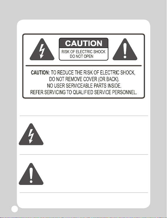
Warning & Caution
This symbol is intended to alert the user to the presence
of un-insulated “dangerous voltage” within the product’s
enclosure that may be of sufficient magnitude to
constitute a risk of electric shock to persons.
This symbol is intended to alert the user to the
presence of important operating and maintenance
(servicing) instructions in the literature accompanying
the appliance persons.
2
Page 4

General Features
• Resolution : 700 TV Lines
• Built in Fixed Lens 3.6 mm
• Min.illumination :
Color : 0.1Lux, B/W : 0.01Lux
• Tact Switch type OSD Control
•
Motion Detection, Privacy Zone, Mirror Function
•
2nd Video-out connector for installer
• Dynamic 3-Axis Movement for Free Lens Rotation
• Power DC 12V
• DNR : 2D
• DWDR: Digital Wide Dynamic Range
Power Wire Maximum Distance
Wire Gauge
18 AWG 200 m
DC12V
3
Page 5
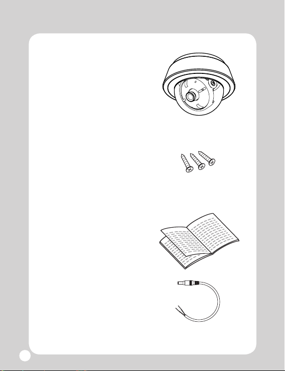
Composition
1. Camera
2. Mounting Screws
Tapping Screws 4 x 25
3 pcs
3. Instruction Manual
Pig Tail
4.
4
Page 6
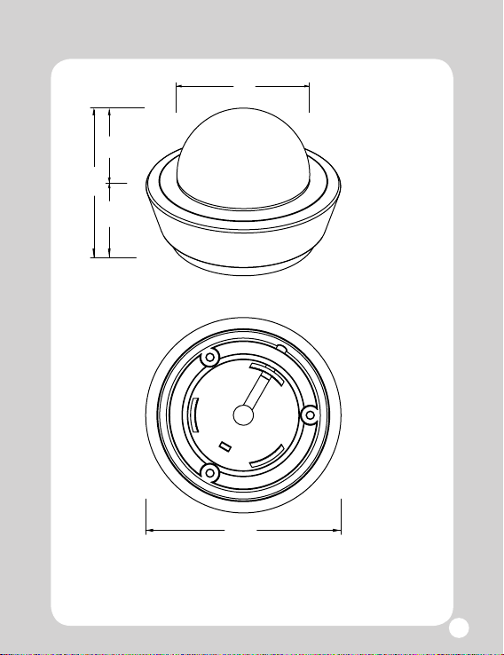
2.5”
Dimension
2.4”
1.2” 1.3”
3.4”
Units : inch
5
Page 7
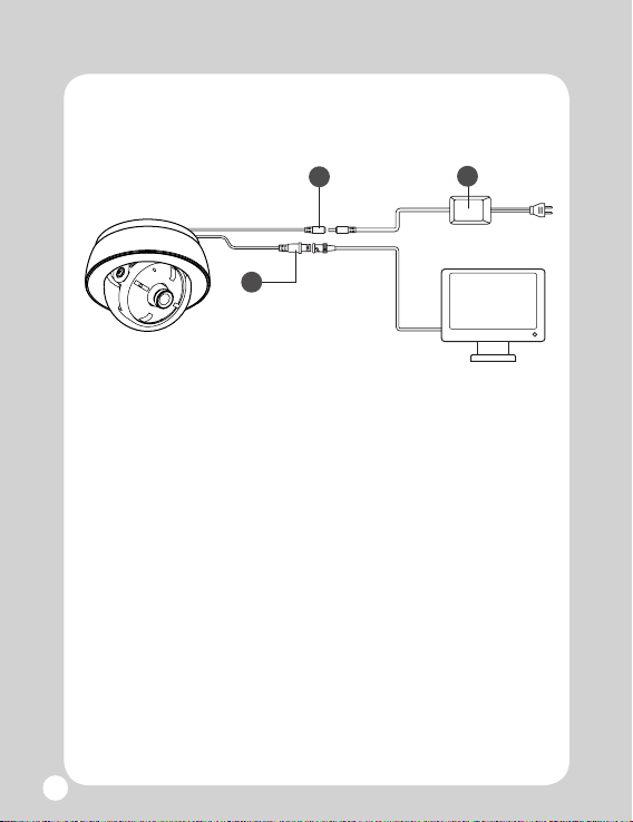
Connection
1. DC Jack
2. Power Adaptor (DC 12V)
3. BNC Jack (Video Output)
6
1
3
2
Monitor
Page 8
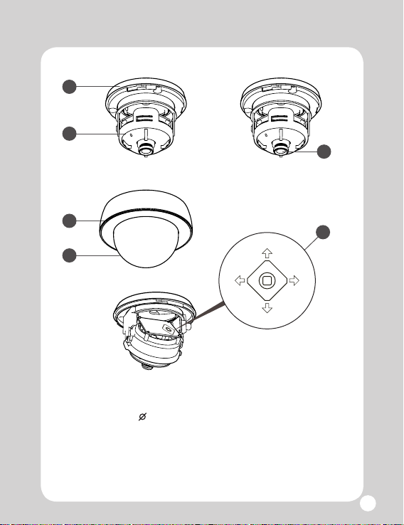
Product Overview
4
3
5
2
1
1. Dome Glass 2.4”
2. Top Cover
3. Main Body
Up
Left Right
Down
4. Bottom Cover
5. Lens
6. OSD Menu Switch
6
7
Page 9
Installation
Refer all work related to the installation of this product
to qualified service personnel or system installer.
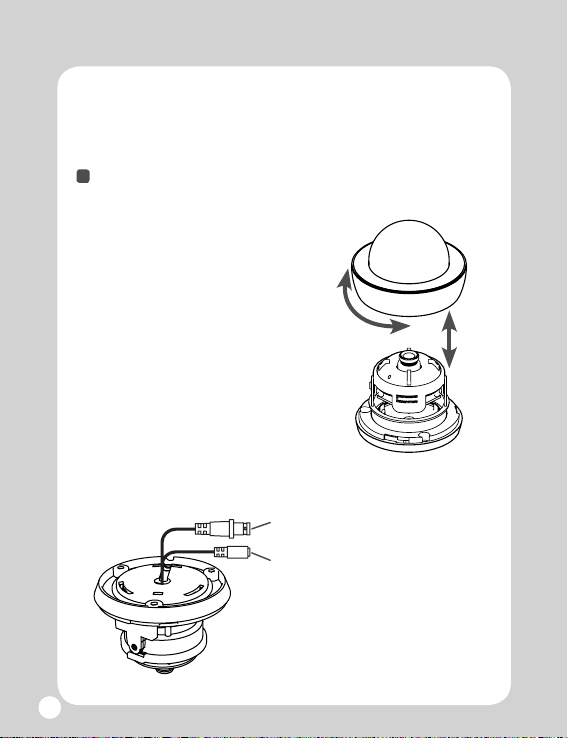
Preparation
1. Remove the Top Cover
a. Gently turn the Top Cover
counter-clockwise to unlock,
then pull free of the Main Body.
b. Set the dome and Main Body
aside.
2. Connect the Wiring
a. Video output connector.
b. Power connector.
8
Page 10

Installation
Camera Mounting
a. Pass the Power Cable and the
Video Cable from the camera
unit through the hole in the
ceiling.
b. Install the Main Body to the
desired installation surface
using 3 supplied mounting
screws.
Camera Adjustment
-
The dome camera has three position adjustments
and OSD Menu Setting Switch.
A
A = Pan rotation
B = Horizontal rotation
C = Tilt rotation
C
B
,
If necessary, loosen the screw that locks the gimbal
*
assembly in place, before adjusting the camera.
9
Page 11

Installation
- OSD Menu Setting is controlled by Tact Switch
type OSD Menu Switch located in backside of
control PCB.
Up
Left Right
Down
OSD Menu Switch
-
After installation and adjustment of the camera
is complete, secure the Top Cover by turning it
clockwise.
10
Page 12

Specification
Type CDD11HW
IImage Sensor
Video System
Total Pixels
Effective Pixels
Scanning Frequency
Scanning System
Sync System
Shutter Speed
Resolution
S/N Ratio
Min. Illumination
Video Output
Gamma
Lens
Auto Gain Control
DNR
Motion Detection
Privacy Masking
WDR
DPC
Sharpness
White Balance
Power
Recommended Power
Outside Control
Operating Temps.
Dimensions
Weight
1/3” Sony Supper HAD II CCD (960H)
NTSC TV System
1028(H) x 508(V)
976(H) x 494(V)
15.734kHz x 59.94Hz
2:1 Interlace
Internal Synce
1/60s ~ 1/100,000s
Max. 700 TVL
50 dB or more (AGC o)
Color : 0.1 lux, B/W : 0.01 Lux
VBS 1.0V p-p/75 Ω
r = 0.45
Fixed 3.6mm
OFF / LOW / MIDDLE / HIGH Selectable
2D-DNR: ON / OFF
ON / OFF (4 Zone ISO Control / Output OSD)
ON / OFF (8 areas)
DWDR
AUTO / MANUAL / OFF
Level Adjustable
ATW / MANUAL / AWC
DC12V / 150mA / 1.8W
Regulated DC12V 200mA Power Supply
OSD
-4° ~ 140F , RH 95% Max
3.4” x 2.5” (Glass Ø 2.4”)
Approx. 0.24lbs
11
Page 13

OSD Menu
12
EXPOSURE
COLOR (W B)
DAY&NIGHT
FUNCTION
MOTION
LENS
HBLC/D-WDR
AGC
2D-DNR
RETURN
WB MODE
R-Y GAIN
B-Y GAIN
RETURN
D&N MODE
C_SUP
A_SUP
RETURN
MIRROR
SHARPNESS
LSC
RETURN
MOTION
AREA
SENSITIVITY
DISPLAY
HOLD TIME
ALARM
RETURN
ELC, DC
OFF
BLC - MODE, WEIGHT
OFF,LOW,MID,HIGH
ATW, MANUAL, PUSH
AUTO, COLOR, B&W, EXT
<0 ~ 100>
<0 ~ 100>
OFF, MIRROR
<0~30>
OFF, ON <0 ~ 30>
OFF, ON
AREA1 ~ AREA4
<1 ~ 30>
OFF, ICON, TRACE
<0~15>
OFF, ON
Page 14
OSD Menu
PRIVACY
SET UP
SYSTEM
EXIT
MASK1
MASK8
RETURN
TITLE
DPC
OLPF
MONITOR
GAMMA
RETURN
CAMERA ID
COMMUNI.
LANGUAGE
OSD COLOR
RETURN
FACTORY
SAVE & EXIT
EXIT
OFF
ON
DOT SEL
DOT XY
MOVE XY
COLOR SET
OFF
ON
DOT SEL
DOT XY
MOVE XY
COLOR SET
AUTO/MANUAL
FILTER 1
CRT
0.45
OFF
BLUE
NO
* Depending on the setting of sub menu, the default
value may be changed.
13
Page 15

OSD Menu Setting
EXPOSURE
The Lens, HBLC/D-WDR, AGC, etc options that are available
in the EXPOSURE menu.
EXPOSURE – LENS
EXPOSURE
LENS ELC
HBLC/D-WDR OFF
AGC HIGH
2D DNR ON
RETURN RET
EXPOSURE – LENS – ELC – E.SHTTER
LENS – ELC
E. SHUTTER AUTO
BRIGHT 050
RETURN
- When selecting in Auto mode(default) : The shutter mode from
1/60 to 1/100000 is controlled automatically.
EXPOSURE – LENS – ELC – BRIGHT
LENS – ELC
E. SHUTTER AUTO
BRIGHT 050
RETURN
14
- Select ELC mode for electronic
shutter AE controls.
- Select DC mode for DC-IRIS
controls.
- E.SHUTTER – setting value of
electronic shutter.
- Select mode : Auto,1/60(1/50),
1/100, 1/120FLK, 1/250, 1/500,
1/1000, 1/2000, 1/4000, 1/10000,
1/100000 sec. (default : AUTO)
- BRIGHT : For target brightness
control.
- AE controls this in compliance
with a set bright control. Bright
control from 1 to 100, the defult
is 50.
Page 16

EXPOSURE – LENS – DC
- DC modes use DC-IRIS lenses and they control AE.
Electronic shutter speed default is 1/60.
EXPOSURE – LENS – DC – E.SHTTER
LENS – DC
E. SHUTTER 1 / 60
BRIGHT 050
DC REF 000
RETURN
EXPOSURE – LENS – DC – BRIGHTNESS
LENS – DC
E. SHUTTER 1 / 60
BRIGHT 050
DC REF 000
RETURN
EXPOSURE – LENS – DC REF
LENS – DC
E. SHUTTER 1 / 60
BRIGHT 050
DC REF 000
RETURN
EXPOSURE – HBLC/D-WDR
EXPOSURE
LENS ELC
HBLC/D-WDR OFF
AGC HIGH
2D DNR ON
RETURN
- LENS – DC mode setting.
- E.SHUTTER : Electronic shutter
value setting mode in DC IRIS.
- 1/60(1/50), 1/100, 1/120FLK, 1/250,
1/500,1/1000,1/2000,1/4000,1/10000,
1/100000 sec.
- BRIGHT : Setting for target
brightness.
- Controls brightness value of DC
IRIS. Bright control from 1 to
100, the defult is 50.
- Control value from 0 to 20, the
defult is 10.
- Select menu for BLC / HLI /
D-WDR
- BLC mode : Back Light
Compensation.
- HLI mode : High Light Inverse.
- D-WDR mode : Digital Wide
Dynamic Range.
15
Page 17

EXPOSURE – HBLC/D-WDR – BLC
EXPOSURE
LENS ELC
HBLC/D-WDR BLC
AGC HIGH
2D DNR ON
EXIT RET
EXPOSURE – HBLC/D-WDR – BLC – BLC MODE
BLC
BLC MODE MANUAL
BLC WEIGHT MID
RETURN
EXPOSURE – HBLC/D-WDR – HLI
EXPOSURE
LENS ELC
HBLC/D-WDR HLI
AGC HIGH
2D DNR ON
EXIT RET
environment, HLI does not operate in DAY conditions.
- You can select 4 mask areas in DAY&NIGHT and adjust HLI level.
16
-Selected BLC mode.
- Select AUTO or MANUAL.
- Sets the total AE level at AE
value of select window area.
- AUTO, selects the darkest area
with automatic and photometry
weight.
- HLI mode : High Light Inverse.
- It is a function which reverses
the area with strong light.
- The HLI BLC mode control by
BLC window area. (HBLC)
- Use mode set of HLI
(ALL DAY / NIGHT).
- ALL DAY : Always operating HLI
- NIGHT : Operating only in NIGHT
Page 18

EXPOSURE – HBLC/D-WDR – D-WDR
- D-WDR captures the images at all light levels by correcting
GAMMA CURVE.
- If you use an ordinary camera in a scene with an intensive
backlight, the object will be displayed dark on the monitor .To
solve this problem, you can use the
D-WDR function is to improve the dark parts without saturation
from bright part.You can adjust SET LEVEL to get clearer images.
EXPOSURE – AGC
EXPOSURE
LENS ELC
HBLC/D-WDR BLC
AGC HIGH
2D DNR ON
SENSE-UP AUTO
RETURN
- AGC : Auto Gain Control level set
OFF / LOW / MIDDLE / HIGH.
COLOR (WB)
The white balance mode and color gain setting menu.
COLOR – WB MODE
COLOR
WB MODE ATW
R - Y GAIN 128
B - Y GAIN 128
RETURN
COLOR – R-Y GAIN
COLOR
WB MODE AWC
R - Y GAIN 128
B - Y GAIN 128
EXIT RET
- White Balance control mode selects.
ATW / MANUAL / AWC>PUSH
- Selection of COLOR – WB MODE - ATW
- ATW : Auto Tracking White
Balance mode
- User can change color.
- The color gain controls R-Y
17
Page 19

COLOR – B-Y GAIN
- The color gain controls B-Y
DAY&NIGHT
- Color & B/W change, D&N lter change, Color/Aperture level
control.
DAY&NIGHT – D&N MODE
DAY&NIGHT
D&N MODE COLOR
C - SUP 030
A - SUP 030
RETURN
operates.
- B&W mode: Only B&W mode operates.
- EXT mode: D&N decision by external CDS signal. (with LED)
DAY&NIGHT – C_SUB
-The color noise suppress in NIGHT mode.
DAY&NIGHT – A_SUB
- The aperture level suppress in NIGHT mode.
- D&N change mode sets.
- Select of AUTO / COLOR / B&W /
EXT.
- AUTO mode: D&N is decided by AGC gain
level.(without LED)
- COLOR mode: Only Color mode
FUNCTION
- Sets for MIRROR, Sharpness, LSC mode
FUNCTION
DAY&NIGHT
MIRROR OFF
SHARPNESS 020
LSC OFF
RETURN
18
- MIRROR : Image mirroring
ON/OFF mode.
- SHARPNESS: Sharpness level
control ( 0 ~ 30, 1 step)
- LSC: Lens Shading Compensation
ON/OFF mode
Page 20
MOTION
- This function informs the user there is motion on the screen.
Up to 4 area zones.
MOTION
MOTION
MOTION OFF
AREA SEL AREA1
SENSITI. 025
DISPLAY TRACE
HOLD TIME 003
ALARM OFF
RETURN
- MOTION : Select operates
ON/OFF
- AREA SEL : Select each area
- SENSITI. : Control MOTION
sensitivity. (0 ~ 30, 1 step)
- DISPLAY: Control alarm mode
when MOTION indicates.
( Select of OFF / ICON / TRACE)
PRIVACY
- The mask controls are for the zones where privacy is necessary.
There are total of 8 mask zones.
PRIVACY – MASK1 ~ MASK 8
PRIVACY
MASK 1 ON
MASK 2 ON
MASK 3 ON
MASK 4 OFF
MASK 5 OFF
MASK 6 OFF
MASK 7 OFF
MASK 8 OFF
RETURN
- The each mask selects ON/OFF
- After selecting each mask, it can
select color, location, area of mask.
19
Page 21

SETUP
- The SETUP mode set USER TITLE, DPC(Dead Pixel Compensation),
OLPF, MONITOR MODE.
SETUP – TITLE
SET UP
TITLE OFF
DPC MANUAL
OLPF FILTER 1
MONITOR CRT
GAMMA 0.45
RETURN
- User sets TITLE ON/OFF.
- The user can edit the TITLE by
selecting ON.
USER TITLE – Text setting mode.
USER TITLE
ABCDEFGHIJKLMNOP
QRSTUVWXYZ 012345
6789 ! “ # $ % & ’ ( ) * +
, - . / : ; <=>? @ [ ] ^ _
CLR POS RET
_ _ _ _ _ _ _ _ _ _ _ _
SETUP – DPC (Dead Pixel Conpensation)
SET UP
TITLE OFF
DPC MANUAL
OLPF FILTER 1
MONITOR CRT
GAMMA 0.45
RETURN
20
/
- TITLE can be up to 64 characters.
- , : Used to modify text.
- CLR: User can remove all text.
- POS: Move text position.
- RET : Accept and return to the
previous menu.
It is the function to compensate
for CCD defect.
- User can select OFF / MANUAL.
- Select MANUAL mode to control
DPC settings.
Page 22

SETUP – OLPF
SET UP
TITLE ON
DPC MANUAL
OLPF FILTER 1
MONITOR CRT
GAMMA 0.45
RETURN
SETUP – MONITOR
SET UP
TITLE ON
DPC MANUAL
OLPF FILTER 1
MONITOR CRT
GAMMA 0.45
RETURN
- This mode is intended for the
factory use only
- The DISPLAY MONITOR mode
can supports two kinds of
displays( CRT/LCD)
SETUP – GAMMA
SET UP
TITLE ON
DPC MANUAL
OLPF FILTER 1
MONITOR CRT
GAMMA 0.45
RETURN
- User can adjust GAMMA level.
- Selecting of 0.45 / 0.60 / 1.0 /
USER.
- After selecting USER mode, the
gamma value adjust 0.20 ~ 1.00.
(0.05 step)
21
Page 23

SYSTEM
- The setting Camera ID, 485 comm., language.
SYSTEM – CAMERA ID
SET UP
CAMERA ID 001
COMMUNI. OFF
LANGUAGE ENGLISH
OSD COLOR BLUE
RETURN
SYSTEM – COMMUNI. (communication setting)
- This mode is intended for the factory use only
SYSTEM – LANGUAGE
- User can set language of OSD menu.
SYSTEM – COMMUNICATION sub menu.
- This mode is intended for the factory use only
EXIT
- EXIT menu allows resetting, saving, or cancelling conguration
setup.
EXIT – FACTORY SET.
SET UP
FACTORY NO
SAVE&EXIT
EXIT
EXIT – SAVE&EXIT.
- After adjusted data, exit OSD menu.
EXIT – EXIT
- Exit whitout saving changed data.
22
- This mode is intended for the
factory use only
- Reset camera setting to factory
default.
- After factory set mode, user has
to enter SAVE&EXIT.
Page 24

Trouble Shooting
No picture
Check if the power is connected correctly.
Check if all the cables are connected correctly.
Camera with heat, abnormal motion black lines
Check if the power supply meets standard.
Check if input power supply changes irregularly.
Blinking Screen
Check if the camera set toward sun or fluorescent lamp.
Check if the connector of Auto Iris Lens is connected
correctly when using.
Unclear Screen
Check if the lens is dirty.
You can wipe the lens with clean fabric or brush.
Check for any irregularity in monitor setting.
No operation of Motion Detection
Check if you set ‘Motion Detection’ mode o.
Check if you set ‘MD Area’ properly.
Incorrect color
Check if you set ‘White Balance’ mode correctly.
23
Page 25

Memo
24
Page 26

Page 27

200 New Highway
Amityville, NY 11701
631-957-8700
1 800 645 5516
www.specotech.com
 Loading...