

Page 1
Speco Access Control System
Quick Start Guide
for 2 & 4 Door Systems with Integrated Power Supply
Models A2E4, A2E4P, A4 & A4P
Document Number 100102-SP REV B
This Quick Start Guide provides simplified instructions on how to get the system up and running. For more
detailed instructions, download the full installation manual, Part Number: 100100-SP from our website,
www.specotechnologies.com
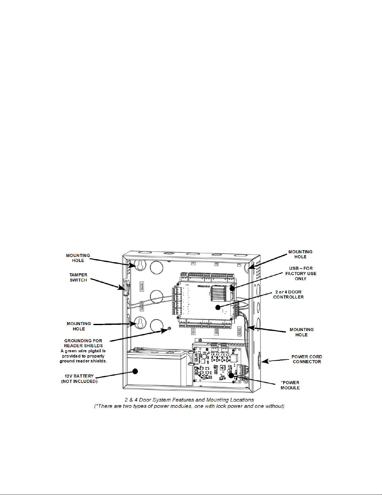
Mounting the Enclosure – 2 & 4 Door Systems
The metal enclosure should be mounted vertically on a wall in a secure location.
1. Run all wires to the enclosure location and label the wires according to their use.
2. Remove the enclosure's door by first unlocking the door and removing the door's ground wire. The door
may be lifted out of the hinge slots, which will provide room for mounting and connecting wires to terminals.
3. Locate the enclosure on the wall and level. Mark the mounting holes on the wall and remove the enclosure
and install anchors appropriate for the type of wall and mounting conditions. The mounting slots are sized
for use with ¼ inch hex head lag screws. Use a length suitable for the mounting conditions but typically not
less than 1 ¾ inch long.
4. DO NOT DRILL the mounting holes while the enclosure is in place on the wall. Dust and debris from drilling
will contaminate and damage the electronics.
5. Partially insert mounting screws into the top two mounting holes and hang the enclosure on the screws.
Check for level, insert the lower screws and tighten all four mounting screws.
6. Run the wires through the knockout holes and connect to the appropriate terminals (see following sections
of the manual for wiring details). Note: Tie down loops are located in the enclosure and are used to provide
strain relief for field wiring connections to the controller.
7. Reinstall the door and reconnect the door's ground wire.
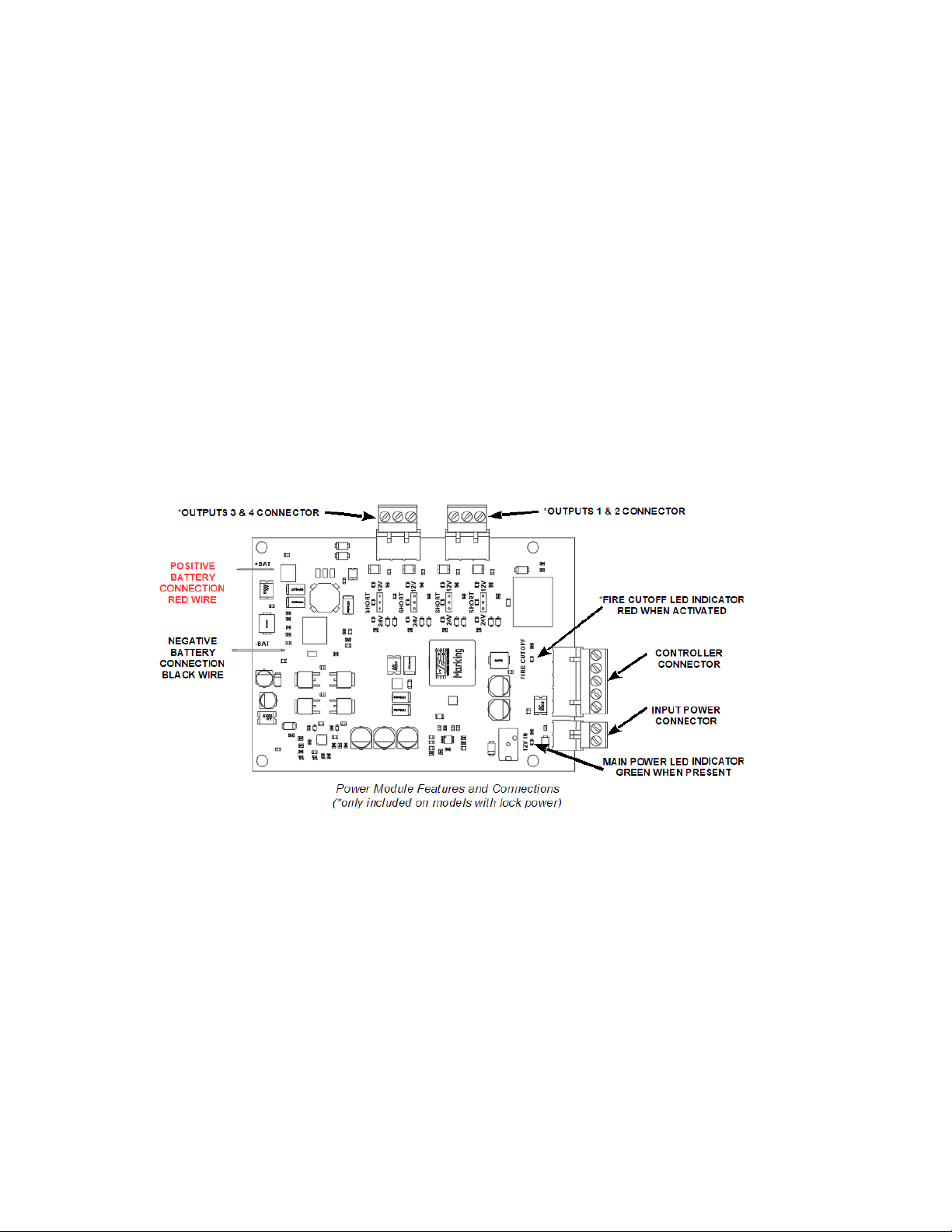
On models that include power for the door locks, the power module has the ability to supply either 12 or 24
VDC power to the door locks. This can be set individually for each of the four outputs. LED's indicate if the output
power is set to 12 VDC (GREEN LED), 24 VDC (AMBER LED) or if the output is overloaded (RED LED). NOTE:
The maximum output current for each of the four outputs is 375 mA @ 24V or 700 mA @ 12V.
Quick Start Guide for 2 & 4 Door Systems with Integrated Power Supply – July, 2019 Page 1
Page 2
Battery Connection
The enclosure provides space and charging for one 12V sealed lead acid battery. When primary AC power is lost,
the battery will provide standby power until the battery voltage reaches approximately 11 VDC at which point the
system will shutdown until main power is restored.
Battery Warnings
Use caution when installing the battery. Incorrect use can damage the battery, power module or can cause
shock or fire.
Connect main AC power before installing the battery. Depending on the condition of the battery, the system
may power up when connecting the battery without an AC power connection.
Only connect one battery to the power module. Do not connect multiple batteries in parallel or in series.
This will damage the system and void the warranty.
The battery charger provides a maximum charge rate of approximately 900mA and will maintain the charge
on a fully charged battery. Ensure that this does not exceed the battery manufacture's rating.
Replace the backup battery every 2 to 3 years.
Properly dispose of old batteries.
The illustrations below show the features of the power module.
On models that include power for door locks, the output voltage can be individually set for each of the four
outputs. Jumpers are used to set the output voltage on the power module and LED's show the status of the output
voltage.
Quick Start Guide for 2 & 4 Door Systems with Integrated Power Supply – July, 2019 Page 2
Page 3

Powering On and Connecting to a Network
Controllers must be located in a secure area and connected to a network that is protected by a security system
(firewall, etc.). Note: a Static IP address should be used when a controller is configured as a server controller.
Client controllers may use DHCP.
In most cases, the controllers IP address will have to be changed to allow the controller to be recognized by the
local network. The controller's IP address is changed as follows.
1. Connect a programming computer directly to the Ethernet port of the controller. A standard CAT-5 cable is
used for direct connection. A crossover cable is not required.
2. Assign a static IP address to the computer of 192.168.0.10.
3. The factory default IP address of the controller is 192.168.0.250. Open a web
browser, such as Google Chrome, and enter the default IP address into the
address bar.
TIP: As an alternative to directly connecting a cable, the provided IP Installer utility can be
used to change the controller's IP address.
4. The controller's login page is displayed as shown. To login enter the default User
ID: admin and default PW: admin
5. Controllers can be licensed as a server or a client. After first time
login, the license page is displayed. To get a license key, first
click on the Edit button. On the next page, click on A, the Get
License Key for a SERVER or click on B, the Get Client Key for
a CLIENT. Click OK to confirm and the license key will be auto
populated. Finish by clicking C, Apply License Key and the
controller will restart.
NOTE: The controller needs to access the
Internet to obtain a license key.
6. When the controller is licensed for a server, after logging in, the system configuration Wizard is started. The
Wizard is a guide that can be used to collect the basic information required to set up a system. The network
settings can be configured in the Wizard or by browsing to the Network Configuration.
7. The network configurations may be also accessed through the Sitemap by first clicking the icon at the
bottom of the page, then clicking IP Address under Network Settings.
8. After entering the network information, click Save & Reboot and the
controller will reboot. Typically rebooting will take less than 2 minutes.
8. After disconnecting the
programming computer, the
controller is ready for the local
network.
NOTE: System data may be lost if the
controller is powered down
without performing Save & Reboot.
Quick Start Guide for 2 & 4 Door Systems with Integrated Power Supply – July, 2019 Page 3
Page 4

Adding Clients to Systems
Some systems have the ability to add additional controllers to increase the number of doors, inputs or outputs or
control elevators. Clients are configured through the system's server, but must first be linked to the server.
Setting the Client's Network
1. Connect a programming PC directly to
the controller as described in the section
Preparing for the Network.
2. Login using the default ID: admin and
default PW: admin
3. After login, the client's network page is
displayed. Click Edit.
4. Change the IP address of the client
controller. It is recommended to set this to
DHCP.
5. Enter the IP address of the server
controller and the server's port number
(the default port number is 20000).
6. Enter the password and click Save.
Linking the Client to the Server
1. Login to the system's server.
2. After logging in, browse to the Site Management and select Client Management.
3. The client will appear in the client management list. Click on the button to connect the client to the
server.
System Configuration and Programming
The controller is programmed and managed using a web browser on any computer connected to the local area
network. The controller's basic settings can be programmed using the Wizard tool. The Wizard tool helps ensure
that required settings are configured for normal operation.
For specific programming instructions, refer to the Users Programming Guide, Part Number 100104-SP.
Contact & Warranty Information
Speco Technologies
200 New Highway
Amityville, NY 11701
Phone: 800.645.5516
FAX: 631.957.9142
www.specotech.com
For Technical Assistance
Phone: 800.645.5516 option 3
email: techsupport@specotech.com
Refer to our website for warranty information.
Document Number 100102-SP REV B
Quick Start Guide for 2 & 4 Door Systems with Integrated Power Supply – July, 2019 Page 4
 Loading...