

Page 1
Quick Start Guide
O2VLB6
Page 2

Warning and Caution
1
■ If the p rod uct d oes not work properly, plea se conta ct your
dealer or the nearest service center. Never attempt to disassemble
the camera yourself. Any unauthorized changes or modifications
could void the warranty.
■ Do not allow water or liquid intrusion into the camera.
■ All installation and operation here should conform to local
electrical safety codes. Make sure the device is firmly installed
on the wall or ceiling.
■ Do not use camera beyond specified voltage range.
■ Do not drop the camera or subject it to physical shock.
■ Avoid touching the camera lens.
■ If cleaning is necessary, please use cleaning cloth to wipe it
gently.
■ Do not aim the c amera at the sun or e xtrem ely brig ht light
sources.
■ Do not place the camera in extremely hot or cold environments
and d u sty a n d damp l ocati o n s. Do n ot ex p ose it to hi g h ly
electromagnetic radiation.
■ Do not block any ventilations.
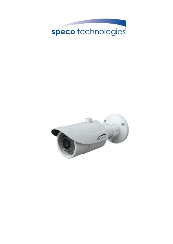
Package
2
Page 3
Camera
Quick start guide
3 tappi ng screws PA 4×25
1 machi ne screw PWM 3×5
CD
Rubber plug
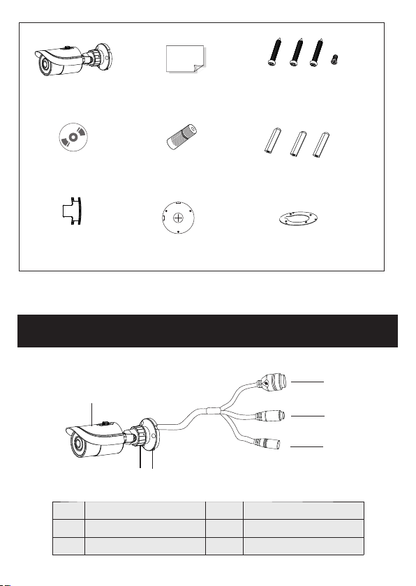
Overview
Overview
3
3
1
2
3
1
Sun-shield
Fixed Ring
Mounting Base
Wate r-p roo f cap
Drill template
2
3
4
5
6
Plastic plug × 3
Adapter Plate
4
5
6
Network Cable
MIC IN Cable
Power Cable
Page 4

able
k c
r
wo
t
Ne
DC12V
* 1 It is recom mend ed to install th e water -proof cap for outdoor installat ions .
* 2 DC 12V pow er su ppl y is no t require d if a Po E swi tch o r injector is us ed to p owe r
the camera.
► Connecting Network Cable
1
2
3
① Loosen th e nut from th e main element.
② Run the net work cabl e (without RJ 45 connector) through both
element s. Then crimp the cable with RJ 45 connector.
③ Connect t he cable to the hermetic connector. Then tighte n the nut
and the mai n cover.
Page 5

Installation
4
* Befor e you start, p lease make s ure tha t the w all or ce iling is str ong enough
to with stand thre e times the we ight of t he ca mera.
① Install j unction b ox onto the wall by using the screws provided.
Sp
on
g
e
Ju
n
ct
ion B
o
x
② Mount the r ubber plu g to the gap of t he mounting base and fasten
the camer a onto the ad apter plate.
A
d
a
pt
e
r Plat
e
Mount ing B ase
Rubbe r Plu g
Page 6

③ Connect t he cables a nd then install the camera onto the junction
box as show n below.
Water -pr oof Ring
Adapt er Pl ate
④ Br acket Adju stment-Lo osen the fixe d ring to adjus t the view
an gle of the ca me ra. After yo u get the optim um angle of vie w,
ti ghten the f ix ed ring to co mp lete the in st allatio n.
Pan 360 °
Tilt 90 °
Fixed R ing
Page 7

Web Operation
5
IP Scanner can search for the devi ce on the local network.
● Operation
① Make sure that the camera and the PC are connected to the same
local network. The camera is set to DHCP by default.
② Install IP Scanner from the CD and r un it after installation.
③ In the device list, you can view the IP address, model number, and
MAC addre ss of each de vice. Sel ect the applicable device and double
click to open up the web viewer. You can also manually enter t he IP
address i n the addre ss bar of the w eb browse r.
Page 8

The login i nterfac e is shown above. Default user name is admin a nd
passw ord is 1234. Afte r l ogg ing in , f oll ow dir ect io ns t o in stall
applica ble plugi ns.
45004 3000617 A0
 Loading...