

Page 1
Complies with UL 1563
Swimming Pool Equipment
Listing #E212148
For Swim Jet Use Only - 400 GPM Swim Jet Combination Fitting
Life: 10 Years - Wall Only - Badu
®Jet
IMPORTANT SAFETY INSTRUCTIONS
INSTALLATION, OPERATING AND SERVICE MANUAL
READ AND FOLLOW ALL INSTRUCTIONS
BADU®JET
Counter Swimming Unit
U.S. Patent No. 3.977.027
OWNER’S MANUAL
2007
F
H
B
D
C
E
A
G
I
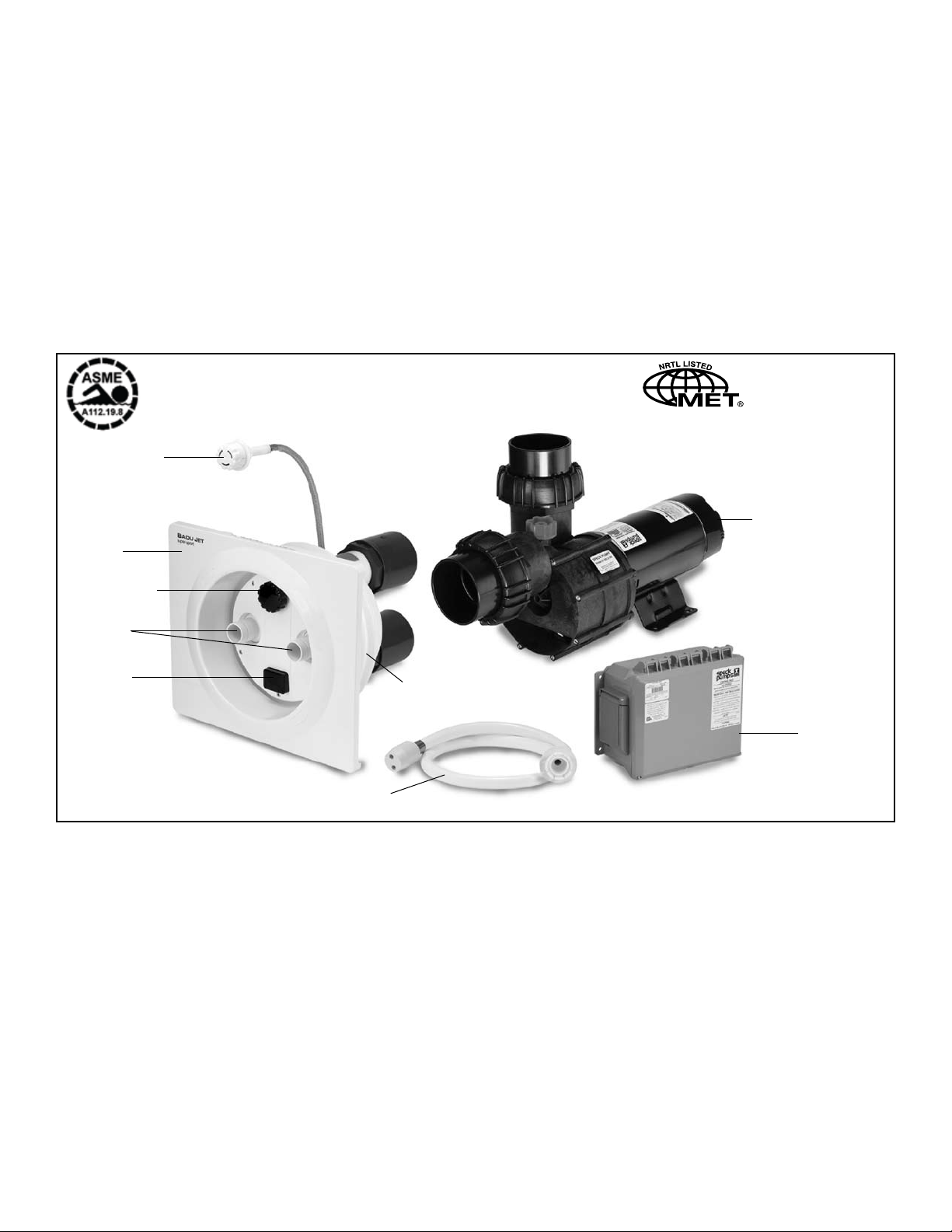
All parts are manufactured of corrosion-resistant material and combined in one single housing that can be
installed in pools of any size and shape.
Key to illustration:
A.
Flush mounted Jet Housing, 16” in diameter
Rectangular, Anti-Entrapment Cover (20” x 17”) for
B.
undetectable pump suction. (Optional Round)
C.
Adjustable Water Flow Jet Nozzle
Water volume control knob adjusts force of water leav-
D.
ing jet nozzles
E.
Pneumatic on/off button guarantees complete electrical separation between pool water, pump motor and
control box.
Air regulator adjusts amount of air bubbles in water
F.
ow.
G.
Control box with GFCI with tubing for pneumatic button.
Speck 4 HP self-priming, plastic pump, single phase
H.
with thermal overload (no motor starter required). Optional three phase motor and control box available (Normal priming pump available for installation below water
level).
I.
Massage Hose with pulsator may be attached to jet nozzle.
Page 2

Page 3

1.
Important Safety Instructions
2.
Introduction and Planning
TABLE OF CONTENTS
Page 2
Page 2
3.
Plumbing for
Concrete or Gunite Installation
4.
Installing
4a.
Liner and/or Fiberglass Pool Installation
5.
Removal of Liner
5a.
Installation of Nozzle Housing
6.
Installation of Anti-Entrapment Cover
7.
Installation of the Pump and the Control Box
8.
Operation Instructions
9.
Nozzle Adjustment Instructions
10.
Winterizing
11.
BADU
BADU
®
JET
®
JET in Existing Gunite or Concrete Pool
Pages 2-3
Page 4
Page 5
Page 6
Page 6
Page 7
Page 7
Page 8
Page 8
Page 9
Page 9
Frequently Asked Questions
12.
Difference Between the
13.
Parts List for the
14.
Parts List for the BADU
15.
Limited Warranty
16.
IMPORTANT INSTALLATION TIPS IN BOLD PRINT
Consult your physician before attempting any strenuous exercise.
This product may not be challenging or satisfying for all levels of exercise.
Classic and the super-sport
BADU®JET Classic
®
JET super-sport
Page 10
Pages 10-11
Page 12
Page 13
Page 14
Page 4
1. Important Safety Instructions
When installing and using this electrical equipment, basic safety
precautions should always be followed, including the following:
A. READ AND FOLLOW ALL INSTRUCTIONS.
B. WARNING: To reduce the risk of injury, do not permit
children to use this equipment unless they are closely supervised at all times. Failure to adhere to this and all other warnings
could result in serious injury or death.
C. A licensed electrician is required for all wiring connections.
D. TO REDUCE RISK OF ELECTRICAL SHOCK, connect all
ground wires to grounding terminal located in the control box.
Use no smaller than a No. 12 AWG (3.3mm
E. TO REDUCE RISK OF ELECTRICAL SHOCK, a bonding
connector is provided on the motor for bonding of local ground
points such as water pipes, metal ladders / handrails, or other
metal within 5 feet of the pool. All local ground points should be
bonded with a No. 8 AWG (8.4mm
as an electrical ground.
F. All electrical equipment should be installed in accordance with
local codes.
2
) wire. Never use gas piping
2
) wire.
G. DO NOT store or use gasoline or other ammable vapors
or liquids in the vicinity of this equipment. DO NOT store pool
chemicals near the equipment.
H. DO NOT remove any safety alert labels such as DANGER,
WARNING, or CAUTION. Keep safety alert labels in good con-
dition and replace missing or damaged labels.
I. Keep and read all equipment manuals. Adhere to all of their
instructions.
J. WARNING: Stay alert, watch what you are doing and
use common sense. DO NOT use unit if you are tired and/or
exhausted. DO NOT use unit while under the inuence of drugs,
or alcohol, or any medications.
K. WARNING: Consult your physician before exercising
with the
L. WARNING: DO NOT use or operate the
if the anti-entrapment cover is missing, broken or loose.
M. SAVE THESE INSTRUCTIONS! Refer to them frequently
and use them to instruct third party users.
BADUJET or using the massage hose.
BADUJET
2. Introduction and Planning
The BADUJET is normally incorporated into the original pool
design. However, it can be added to any pool at a later date.
The B
ADUJET has no protruding parts, and ensuring the
pool user’s safety. It is very compact and installs at minimal
cost.
The B
ADUJET can be installed in any size pool. We suggest
a minimum pool size of 7 ft. wide, 14 ft. long and 3 1/2 ft. deep
in order to swim. Most prefer 16 ft. in length or longer. The extra
length allows the swimmer to comfortably drift back and swim
up stream.
Consult local codes for minimum distance between pump and
pool. Locate pump as close to the B
ADUJET as practical.
3. Plumbing for BADU®JET
The BADUJET assembly package contains all necessary
parts for the installation of the unit into concrete, gunite, liner or
berglass pools.
CAUTION: All necessary screws and bolts included with the
BADUJET are stainless steel or plastic. ALL screw threads
and threaded inserts are METRIC! ONLY METRIC bolts and
nuts may be used! The one exception is the connecting thread
Use at least 4” pipe when distance between jet housing and
pump is 30 ft. or less and 6” for pipe runs longer than 30
ft.
The 4 HP, self-priming, plastic pump has a single phase motor with thermal overload (no motor starter required). The
4 HP single phase motor draws a maximum of 19.4 amps
@ 230 V. The unit requires a minimum circuit of 30 amps.
Install a 40 amp breaker to avoid nuisance tripping when
pump is turned on and off frequently. The starting current
of the 4 HP motor can reach up to 6 times the running currents. (Three phase motor draws a maximum of 12.8 amps
@ 230 V and 6.4 amps @ 460 V).
for the intake and delivery connections on the
pump housing.
CAUTION: The adaptors on the housing are factory mounted and should never be removed. Removal of these adaptors
will void warranty.
CAUTION: The pressure connection must be located
exactly ABOVE the suction connection.
BADUJET and
2
Page 5
Pool WallClamping Ring Gasket
Pump 110mm/4"
9.00"
7.40"
6.45"
14.00"
13.50"
12.65"
Cover
15.30"
13.25"
11.80"
13.00"
15.75"
12.60"
1.5"
7.80"
Connection to
Pump 110mm/4"
Connection from
Protective Jacket
Air Hose
Water Level
Air Tubing
17.45"
20.65"
4"
10.00"
6.4"
Volume Control Knob
Water Level
Jet Nozzle
Pneumatic Button
Rectangular anti-vortex cover
Air Regulator
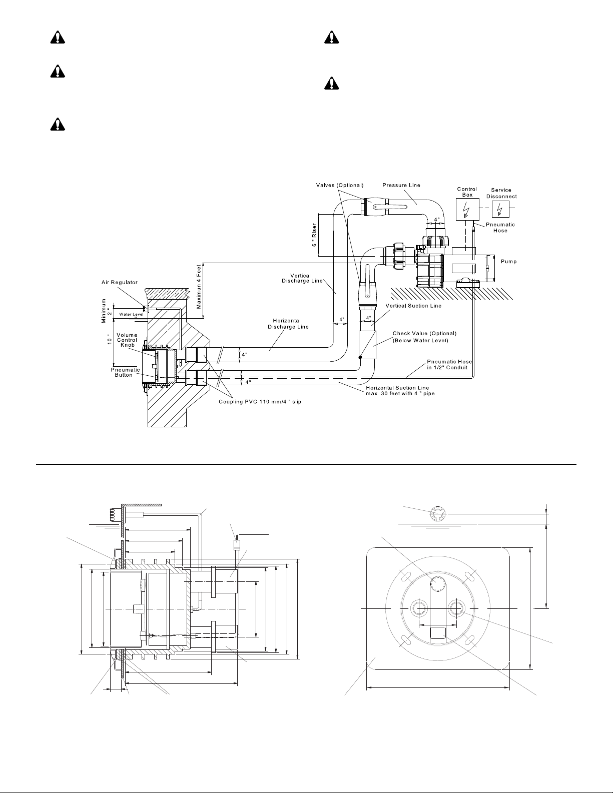
CAUTION: The suction line should run below water level
right up to the pump location.
CAUTION: The center of the housing (the nozzle) should
be 10” BELOW water level for maximum efciency. The air
regulator should be approximately 4” ABOVE the water level.
(See g. 1)
CAUTION: For trouble-free pump priming (up to 4 ft.) rst
install a 6” riser on top of the pump. Then install an elbow and
lead the pressure line downward to the pressure connection at
BADUJET housing.
the
CAUTION: In areas with soft soil conditions or with frequent
earth movement, a exible section of 4” hose should be attached
to the back of the jet housing to prevent plumbing breakage.
CAUTION: Throughout the entire installation, make
sure plumbing connected to the
is well supported. Unsupported plumbing will crack the
BADUJET housing.
BADUJET housing
Fig.2
Fig.1
Note: Encase jet housing and at least 2 to 3 inches of plumbing with concrete.
Note: Valves are recommended when pump is installed below water level.
Fig.3
3
Page 6
Air Control
0.25"
0.5"
1.7"
10.0"
Water Level
Top
14.0"
0.3"
BaduJet
4"10"
Water Level
Pressure
Suction
Housing
Air Line
M8x80
M8x40
110mm / 4" slip
plumbing with concrete.
Air Tubing
Protective Jacket
Coupling PVC
NOTE: Encase jet housing
and at least 2 to 3 inches of
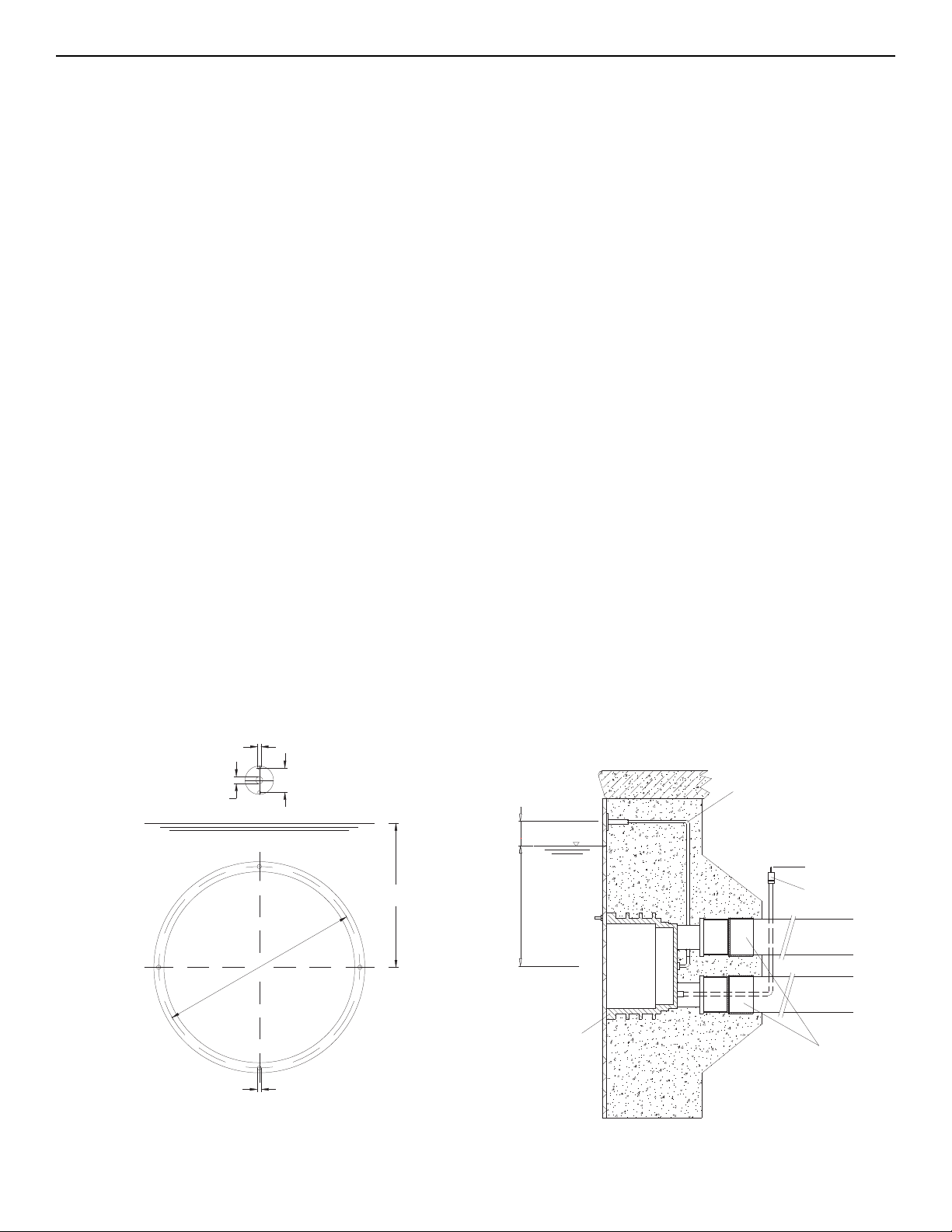
4. Concrete or Gunite Installation
A. Pre plumb BADUJET housings.
1. Install the two PVC SCH 80 couplings 110mm/4” slip (part
#2a) on the PVC SCH 80 ttings 110mm (part #2) which are
premounted on the jet housing.
2. Install approximately 12” of 4” SCH 40 pipe to both suction
and discharge couplings on the jet housing. NOTE: If plumbing
exceeds 30’ between jet housing and pump, increase pipe size
to 6”. Install a 6 x 4” reducing bushng as close to jet housing as
possible.
3. Install approximately 18” of 1/2” conduit to back of jet housing.
(Conduit connector part #3).
4. Install air control PVC hose (part #7) and Y socket (part #6)
assembly to hose socket insert ttings (part #4). Use hose
clamps (part #8) to secure hose to insert tting.
B. Mount the protective cover plate (part #30) to jet housing using stud bolts M8 x 80 (part #31). Tape edge of cover plate to
jet housing. The cover plate and stud bolts are solely used for
installation and can be discarded afterwards. Keep concrete out
of threaded inserts and out of the inside of the housing.
C. Place jet housing into reinforced steel (see g. 7). Jet housing
location is very important.
1. Locate pressure connection exactly above the suction connection.
around the housing approximatley 1 1/2” deep to allow marcite
to seal against the housing.
4. Recheck location of Jet housing when gunite is being applied.
The force of the gunite may move the jet location.
5. To avoid stress on the jet housing, we recommend that the
BADUJET housing be encased with gunite and at least 2 to 3
inches of the plumbing stub out is covered with gunite.
NOTE: Stress on the plumbing may crack the BADUJET
housing.
D. Air regulator installation should be approximately 4” ABOVE
the water level.
1. Air regulator holder (part #9) and hose socket insert tting
(part #5) connect to PVC hose (part #7). Make sure air regulator holder face is tapped over to prevent gunite from entering
holder.
2. Air regulator can be located in the tile line above water line or
in the deck.
E. Keep all parts not being used now in original box. Store in a
safe place until needed.
F. The following is a list of all parts that ARE NOT USED IN A
GUNITE INSTALLATION:
2. The center of the housing (the nozzle) should be 10” BELOW
water level for maximum efciency.
3. Front edge of Jet housing should nish even with inside gunite
wall. Make sure a V shaped groove is scraped out
1. Gasket w/knobs part #26
2. Clamping ring gasket part #27
3. Counter sunk bolt part #10
4. Washer M6 part #12
5. Nut M6 part #11
6. Counter sunk bolt part #98
Fig. 4
Template for Installation in Gunite or Concrete Pools.
4
Fig. 5
BADUJET in Concrete or Gunite Pool.
Page 7
Beam
10"
24"
36"
Water Level
19"
19"
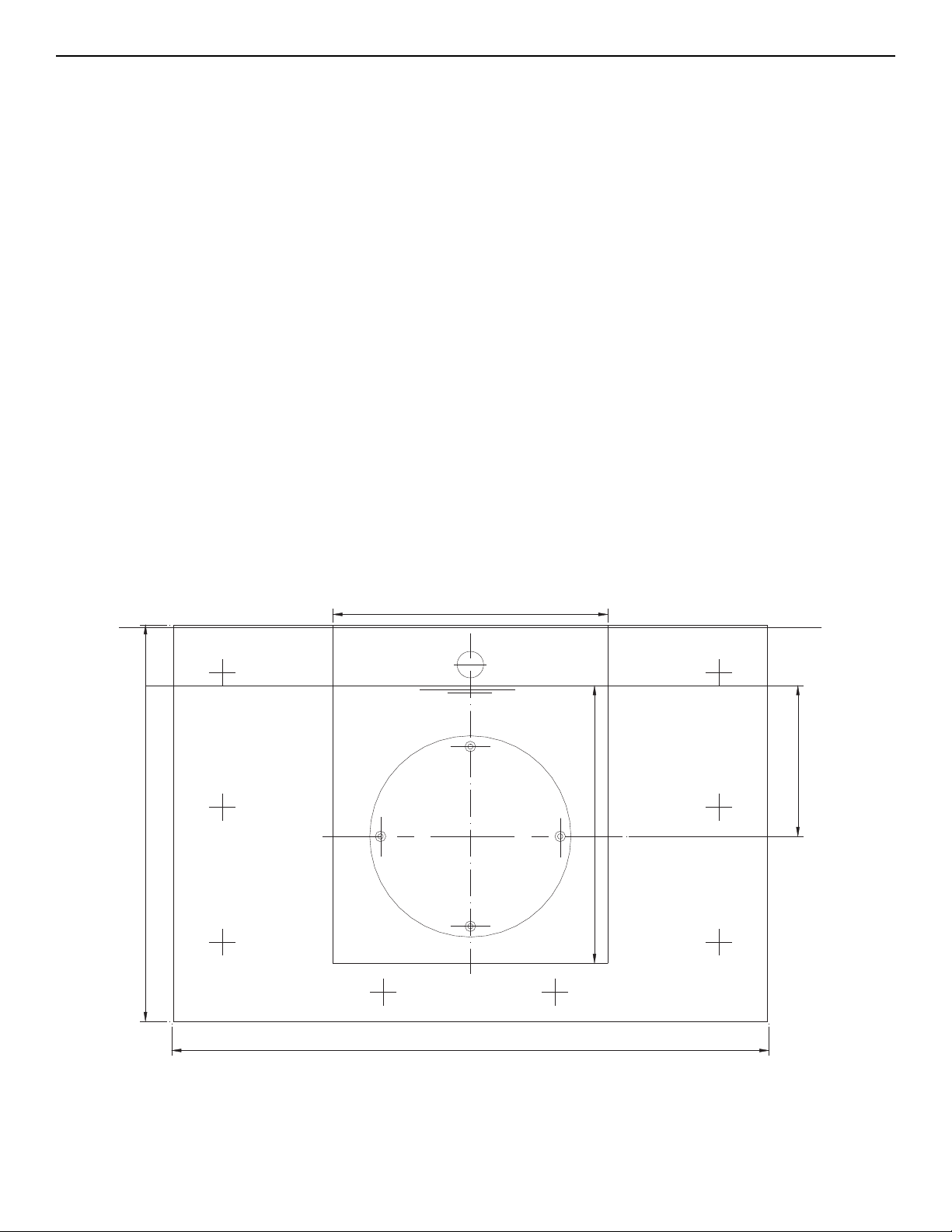
4a. Installing in Existing Concrete or Gunite PooI
Materials: 1 piece of Plywood 2’ x 3’ x 1/4”
8 Lag screws 1/4” x 1 1/2” (minimum)
8 Plastic lag anchor shields
Step 1. Carefully choose the location in which
to be installed; it should be a at srface with no or very little
crown.
With a concrete saw, cut out the outline of the section to be
chiseled out with an air hammer or equal. This hole should be
19” wide x 19” down from the water line. The bonding rods on
the cap of the pool should be left intact, while all other steel rods
should be cut back to clear the placement of the jet housing.
Step 2. Taking the 2’ x 3’ x 1/4” plywood, set its top edge even to
the cap of the pool wall. In some cases a larger piece of plywood
maybe needed to cover the hole completely. If plywood covers
the hole, mark the water line on the plywood. From this line,
layout and drill holes in plywood for the air regulator, the four
BADUJET housing installation studs, and the eight 1/4” lag
screws. NOTE: See Fig. 5a for layout measurements.
Insert installation studs (part #31)in jet housing; one at the top,
the bottom of the vertical center line and on each side on the
horizontal center line. Place cover plate on studs covering the
inside of the jet housing. Next place plywood on the studs and
secure with washers and nuts.
BADUJET is
Now place this assembly into position in the pool wall and align
the water line marks. With a level on the two horizontal studs,
level the assembly and mark the 8 holes for the 1/4” lags. Remove assembly and drill holes for lag anchors. Reposition the
assembly and secure lags. It is best to check with a level before
tightening the lags down. Back ll and form the outside of pool
wall.
Step 3. Mix compound that is compatiable and has good bonding characteristics to the pool wall compound. Pour mixture into
form. Use a mallet and lightly tap the front of formed assembly
to settle mixture, and avoid any air bubbles in the pour. It should
be lled to the top of the plywood. Let mix cure and then remove
plywood form and cover plate. Drill out plastic lag anchors and
feather in pool wall nish. Replace tile and coping. Remove assembly studs and install nozzle housing and anti-entrapment
cover. (See Sections 6 & 7)
Throughout the entire installation, make sure the plumbing con-
nected to the
ported plumbing will crack the
stress on the plumbing, we recommend that the
housing be encased with gunite and at least 2 to 3 inches of the
plumbing stub out is covered with gunite. Stress on the plumbing may crack the housing.
BADUJET housing is well supported. Unsup-
BADUJET housing. To avoid
BADUJET
Fig. 5a
Layout for installing in existing gunite or concrete pools.
5
Page 8
Air Control
0.25"
0.5"
1.7"
10.0"
Water Level
14.7"
Top
13.3"
0.3"
14.0"
15°
30°
5. Liner and/or Fiberglass Pool Installation
CAUTION: Locate pressure connector exactly
above the suction connection. Pressure and suction connectors must be exactly vertical or the rectangular cover
will be uneven in appearance.
CAUTION: Center of housing (the two nozzles)
should be 10” BELOW water level for maximum efciency.
CAUTION: Gasket with knobs (part #26) goes BEHIND pool wall.
CAUTION: Clamping ring gasket (part #27) goes in
FRONT of pool wall. A good RTV silicone may be used
with gasket when mounting jet housing, but in most cases
is not necessary. Installer should decide whether or not
silicone is necessary.
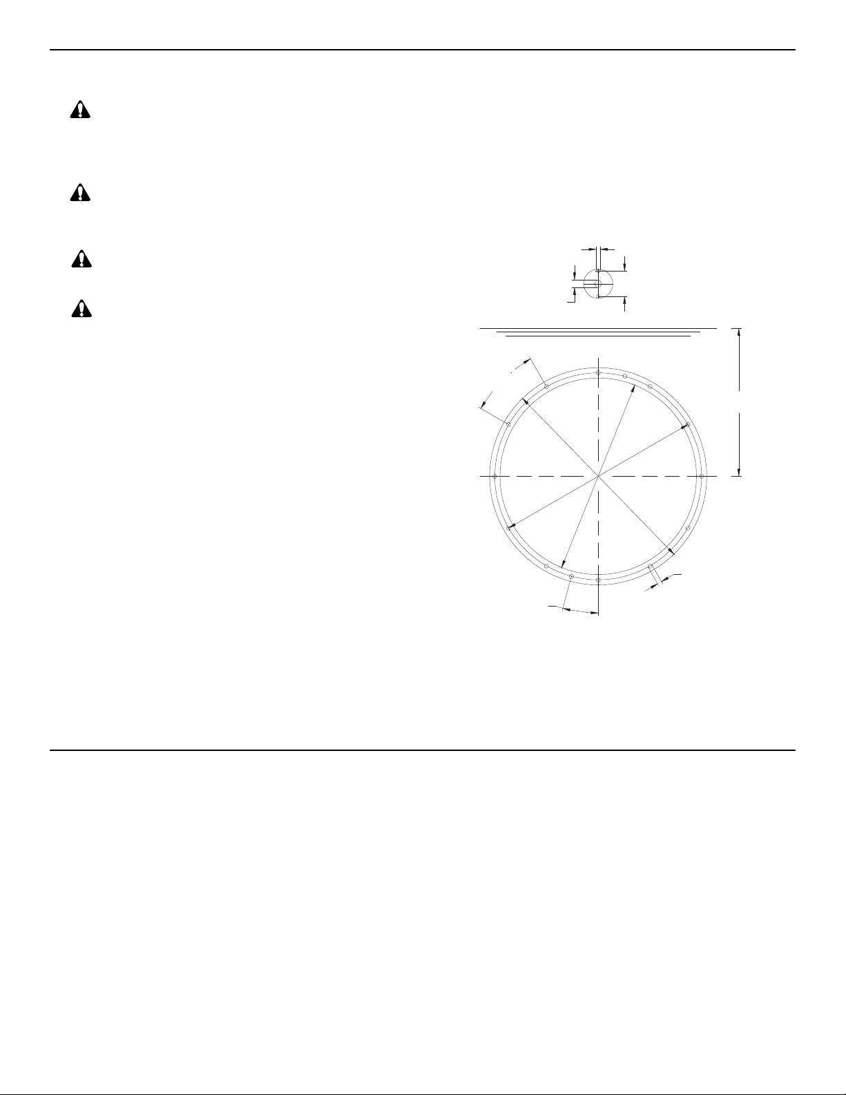
The template provided should be used to mark and drill
the holes as shown in g. 6. For the air regulator, one 1/2”
hole must be provided, preferably along the vertical axis,
approximately 4” ABOVE the water line.
For Liner pools only, two additional 1/4” holes need to
be made on either side of the 1/2” hole. (see Fig. 6)
NOTE: The list below shows all parts that ARE NOT USED
IN A FIBERGLASS/VNYL LINER INSTALLATION:
1. Cover Plate part #30
2. Stud Bolt M8 x 80 part #31
3. Washer M8 part #32
4. Nut M8 part #33
Use the two countersunk bolts M6 (part #10), two nuts
(part #11), and two washers (part #12) to fasten holder
to wall with bolt heads on poolside and nuts on backside.
This will keep the holder attached to pool wall for liner
installation or replacement. NOTE: Gasket (part #13) with
larger holes on the outside, ts over screw heads between
inside of pool wall and liner. This gasket may be held in
place with silicone during liner installation.
5a. Removal of Liner
When replacing liner or removing liner for repairs; remove
4 bolts (part #95) which hold square cover (part #93) to
jet housing. Remove all bolts (part #29) except top two,
which hold the clamping ring (part #28) and gasket (part
#27) to jet housing. Back out the two remaining bolts approximately halfway and check for any movement of jet
housing from the wall. (NOTE: If the two counter sunk
bolts (part #98) which hold the jet housing to the wall were
installed, the jet housing should not move, and the two
Fig. 6 Cutout in Pool Wall 13.3” for BADUJET Housing.
The two holes at 15
o
from the vertical axis and the two
holes at the air regulator will allow both housing and air
regulator to be mounted with countersunk screws (M8 jet
housing / M6 air regulator) before the liner is place.
remaining bolts can be removed.) Remove one of the remaining two bolts and slide clamping ring (part #3) to the
side. Replace all the bolts before removing the last bolt.
Remove or replace liner. Reverse process to install liner.
NOTE: When replacing clamping ring and bolts: locate
bolt heads under liner, make small cut on liner at the bolt
heads and push liner over bolt head.
6
Page 9
6. Installation of Nozzle Housing
Make sure BADUJET housing and threaded inserts are
clean. Nozzle housing can be mounted once pool is complete. Pull the volume control knob off the spindle (snap
connection). Remove nozzle cover.
Unscrew control disk (part #63) from control spindle. Slide
disk on to the 4 prongs at the top of the housing in front of
the pressure connection.
VERY IMPORTANT: Make sure shaft side of disk faces
nozzle housing (part #53).
Connect air tubing (part #47) to air button (part #38/1)
and secure with stainless steel clamps provided. Use end
crimper/cutter to gently tighten clamps. DO NOT OVER-
CRIMP.
Insert preassembled nozzle housing with jets and control
spindle counter-clockwise into the regulator disk.
Important: Make sure the end of the 1/2” PVC conduit containing the air tubing ends above the water level and is
sealed off with gasket and nut (parts # 16-20) to avoid air
intake through the conduit.
Important: Use ALL screws & bolts to guarantee absolute
stability. Tighten all screws and bolts snugly. Insert screws
& bolts carefully to avoid damage to the inserts.
Attach cover plate to nozzle housing with the 5 self tapping
screws (part #49). The volume control knob and cap for air
button can now be snapped into place.
7. Installation of Anti-Entrapment Cover
CAUTION: This unit has a rectangular, anti-entrap-
ment cover. Mount rectangular cover onto the clamping
ring (part #28) with four (4) bolts (M8 x 20) and cover the
openings with the rectangular covers (part #96).
The longer stainless steel bolts (M8 x 80) must be used
if a distance has to be bridged when tiles are attached to
the concrete.
OPTIONAL - Original round style, double ring, antientrapment cover available for curved pools walls.
CAUTION: (For original round style, double ring, anti-
entrapment covers only.) This unit is equipped with two
ring covers. The shallow ring with four attached bushings
mounts over the deeper ring. Four plastic counter sunk
bolts secure the two rings to the jet housing.
The ring covers should be fastened directly to the
JET housing with four (4) plastic bolts (M8 x 45).
CAUTION: DO NOT use force when tightening these
plastic screws. Allow ring covers to snap into place elastically and snugly. The longer stainless steel bolts (M8 x
100) must be used if a distance has to be bridged when
tiles are attached to the concrete.
BADU-
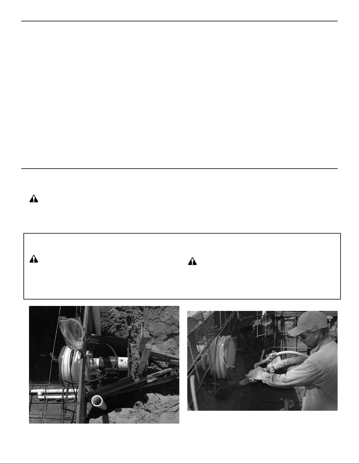
Fig. 7
Setting the
Fig. 8
BADUJET Ready for Guniting
BADUJET housing into reinforced steel
7
Page 10
8. Installation of the Pump and the Control Box
This section concerns the electric motor and control box
only since all other parts, the pump, the jet unit, etc. have
complete and absolute separation from the pool water.
CAUTION: Before installing the Speck Pump, read
the entire pump owner’s manual found in the pump box.
Consult local codes for minimum distance between pump
and pool. Locate pump as close to the pool as practical.
The air button works up to 50 ft. There is 50 ft. of air tubing
in the BADUJET box. An adaptor (part #81) is provided
when additional tubing needs to be used in the event of
replacing a section with locally purchased air tubing.
WARNING: To reduce the risk of injury, do not permit
children to use this product unless they are closely supervised at all times.
9. Operation Instructions
The wiring of the pool motor and control box should
be done by a licensed electrician in accordance with
local codes. Be certain that the motor frame and control box are grounded. Motor name plate has voltage,
phase, amp draw, and other motor information as well
as wiring connection instructions.
BONDING: As required by National Electrical Code Ar-
ticle 680-22, the pump motor must be electrically bonded
to the pool structure (reinforced bars, etc.) by a solid copper conductor not smaller than No. 8 AWG via the external copper bonding lug on the pump motor.
GROUNDING: Permanently ground the pump motor and
control box using a conductor of appropriate size. Connect to the No. 10 green headed ground screw provided
inside the motor terminal box.
NOTE: Do not connect to electric power supply until unit
is permanently grounded.
Remove red lter plug or strainer tank lid on pump and ll
pump with water. Replace red lter plug. Push pneumatic
button on the BADUJET housing. For the rst start-up
allow approximately 5 minutes for the pump to prime. If
the pump has not started priming after 5 minutes, the
amount of water in the pump was not sufcient. Add more
water.
The BADUJET’s volume control knob enables the swimmer to regulate the volume of water released through the
jets. Turn unit off before turning volume control knob.
(Turn clockwise to reduce ow up to 12 complete 360 degee rotations.)
The swivel nozzles of the BADUJET can be positioned
in various directions, allowing swimmers to use various
swim styles.
To start swimming, jogging or running it is suggested that
the two nozzles are pointed slightly inward and slightly
upward so that the water “breaks” approximately 3 ft. in
front of the BADUJET. Start swimming with only minimal
force in arms and legs until you feel yourself drifting backwards, then add force and swim upstream until a proper
balance is found between force and endurance.
Keep in mind that this unit is designed for balanced workout. Find a pace that you can keep up for at least 20 minutes. Out pacing is always possible. The idea is to continue exercise for an extended period of time. The air
regulator permits a controlled mixture of air into the water
ow and creates a unique, invigorating, bubble bath effect.
It will also add additional resistance to swim against.
A pulsating massage hose can be attached to one of the
nozzles for massages.
Directions for use: Consult your physician before using
the massage hose. To reduce the risk of injury, do not permit children to use the massage hose with pulsator unless
they are closely supervised at all times. Turn the BADU-
JET off. Close air regulator. Reduce the volume of water
by turning the volume control knob clockwise, slide the
cap (part #84) on one nozzle and lock into place. Slide
cap of massage hose on the second nozzle and lock into
place. Hold pulsator and turn the BADUJET on. Massage as advised by your physican.
Under certain conditions it is possible that the current
“drifts off” the left or the right from the middle due to water
bouncing off the back wall. In the event that it interferes
with your swimming action, turn unit off for a few minutes
and restart.
WARNING: Do not use or operate the BADUJET
if the anti-entrapment cover or original round style,
double ring, anti-entrapment cover is missing, bro-
ken, or loose.
8
Page 11
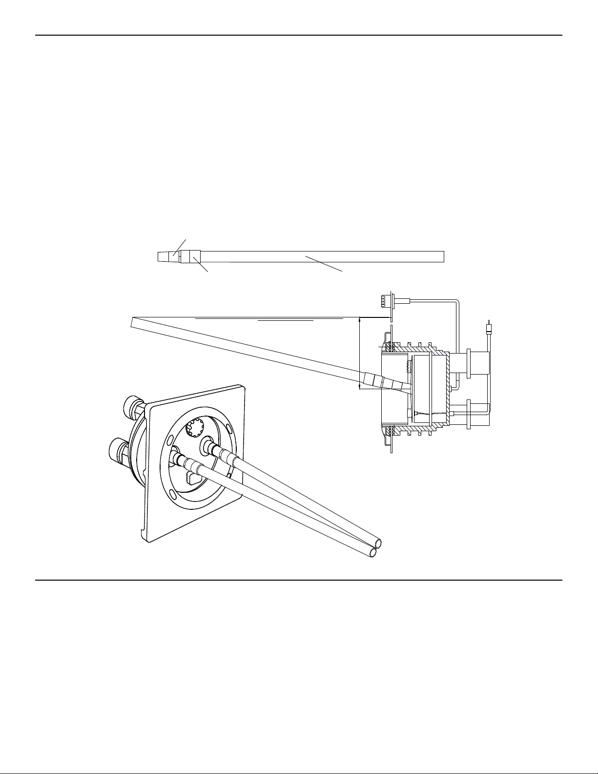
Side View
PVC Pipe 1 1/2" x 4'
PVC Coupling 1 1/2"
Hose Adapter 1 1/2"
10"
Perspective View
Water
10. Nozzle Adjustment Instructions
When setting the nozzles for basic swimming, it is recommended that you set the nozzles in such a way that each
nozzles intersects 4 feet away, while at the same time
breaks the surface.
To help set the nozzles in a neutral position, please follow
these instructions:
1. Parts required:
2 PVC Pipe - 1 1/2” x 4’
2 PVC Adaptor - 1 1/2” Male x Hose
2 PVC Coupling - 1 1/2” Slip x 1 1/2” Slip
Note: Hose adaptor 1 1/2” MPT x hose and female adaptor
1 1/2” FPT x 1 1/2” slip can be used
2. Glue ttings and pipe
3. Insert each jet adjustment tool into jet nozzle.
4. Move each jet adjustment tool toward each other until
each pipe touches at water level.
5. Remove jet adjustment tool.
11. Winterizing
In areas subject to freezing water temperatures, you
should protect your equipment from the freezing temperatures. You can protect your swimjet system the following:
Drain pool until water level has dropped below the rectangular or round cover (part #93). Then protect pump by
removing drain plug and red ller plug (or lid).
9
Page 12
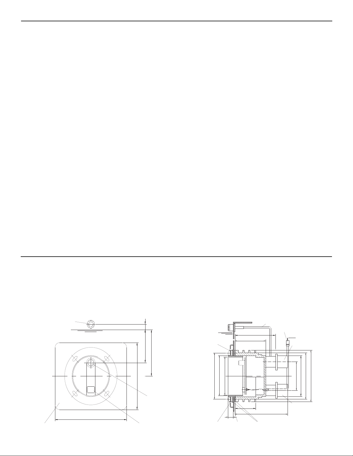
12.4"
14.7"
4"
11.5"
Water Level
Jet Nozzle
Pneumatic Button
Rectangular anti-vortex cover
Air Regulator
10.0"
10.74"
1.5"
Pool WallClamping Ring Gasket
Pump 3"
7.12"
10.00"
9.30"
8.66"
Cover
10.62"
9.21"
5.11"
Connection to
Pump 3"
Connection from
Protective Jacket
Air Hose
Water Level
Air Tubing
8.46"
4.60"
8.00"
12. Frequently Asked Questions
What size pool do I need? The
BADUJET can be in-
stalled in any size pool. However, we recommend a minimum length of 14 ft. and a minimum width of a swimming
lane.
What size plumbing is necessary? How far away
from the
BADUJET can the pump be installed? Use
4” plumbing up to 30 ft. For runs longer that 30 ft. use
6” plumbing. The pump can be placed as close to the
BADUJET as local codes will allow.
How many amps does the pump operate at? Maximum
19.4 amps @ 230 V.
What size breaker do I need? You must use a 40 amp
breaker to avoid nuisance tripping.
BADUJET approved? Yes. The BADUJET
Is the
swim jet system is listed by MET and complies with UL
standard 1563 Swimming Pool Equipment, and ASME
standard A112.19.8-2007 Standard for Swim Jet Combination Fittings.
Should this be tied into my lter system? No. The swim
jet system and the lter system should not be plumbed together as they each provide very specic functions.
Do I need to install a motor starter? No. The pump has
a built-in thermal overload.
Does it matter if the housing is installed higher or
lower than the manual states? Yes, the center of the
housing must be 10” BELOW water level for proper performance of unit.
Can the air regulator be placed elsewhere? Yes. As
long as it is not continuously ooded with water.
What if water is discharging out of the air regulator
when pump is running? The screws (part #51) that
mount the nozzle housing (part #53) are not fully tightened OR o-rings (part #62) on the tension cup (part #59)
are missing or have rolled out of position during installation.
Can the pump be placed below water level? Yes. However, for best performance we recommend ordering pump
for ooded suction (Model 21-80/33 G) instead of self-
priming (Model 21-80/33 GS). We recommend installing
valves for ease of maintenance.
How far away can the air button function properly? A
maximum of 50 ft. Consult factory for distances over 50
ft.
Can I use with automated controls? Yes. It comes with
the ability to tie into automated control systems or other
switching devices.
13. Difference Between the Classic and the super-sport
General:
The BADUJET Classic is smaller in diameter (12” instead of 16”). It has only one jet and no regulator knob
to adjust the ow of water. The jet nozzle itself is adjust-
able.
10
Fig. 2
1. Plumbing the BADUJET Classic
The center of the housing should be 11.5” (instead of 10”)
BELOW water level for maximum efciency. The suction
and discharge line may be 3” instead of the 4” required
for the large unit.
Fig. 3
Page 13
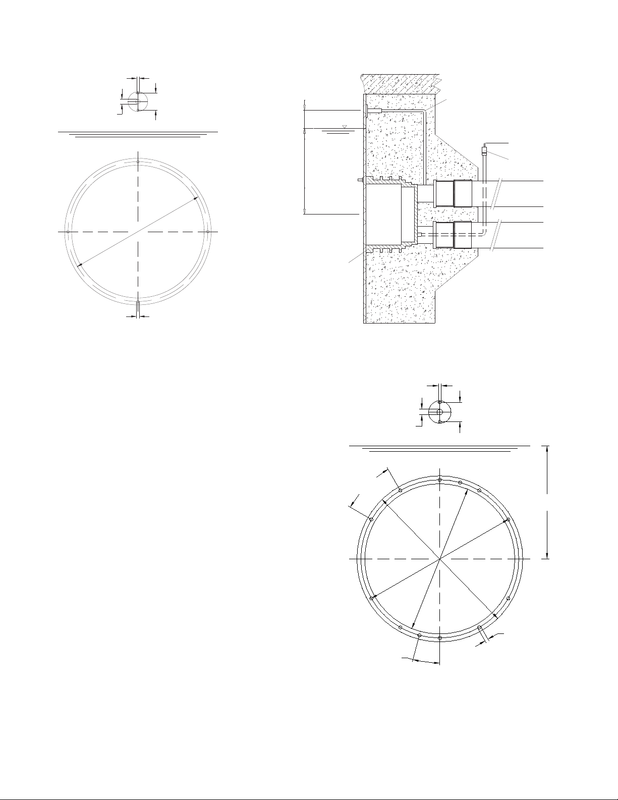
Air Control
0.25"
0.5"
1.70"
Water Level
Top
10.00"
0.25"
NOTE: Encase jet housing
and at least 2 to 3 inches of
BaduJet
4.0"11.5"
Water Level
Pressure
Suction
Housing
Air Line
M8x60
M8x40
plumbing with concrete.
Protective Jacket
Air Tubing
0.25"
classic6
36°
18°
10.00"
Air Control
0.25"
0.5"
1.7"
10.0"
Water Level
10.75"
Top
9.25"
2. Concrete or Gunite Installation
The screws used to mount the ring cover are M6 instead of M8.
Fig. 4 Fig. 5
3. Liner and/or Fiberglass Pool Installation
The center of the housing should be 11.5” BELOW wa-
ter level for maximum efciency. Place gasket with knobs
(part #26) BEHIND pool wall. Place clamping ring gasket
(part #27) in front of pool wall.
The two holes at 18” from the vertical axis and the two
holes (top & bottom) at the air regulator will allow both
housing and air regulator to be mounted with countersunk bolts (M6) before the liner is placed.
4. Installation of Housing
The
BADUJET has no control knob, therefore the pre-
assembled nozzle housing with jet can be inserted directly
into the jet housing. Next, the 6 bolts M6 x 25 (part #52)
and the 5 bolts M6 x 100 (part # 51) are screwed into the
housing.
5. Adjusting Flow
The BADUJET adjustable ow nozzle enables swimmer
to regulate the volume of water released through the jet.
Turning the nozzle clockwise reduces the ow.
All other instructions are the same for both the BADU-
JET Classic and the BADUJET super-sport.
PLEASE READ ALL BADUJET INSTRUCTIONS BEFORE INSTALLATION!
11
Page 14
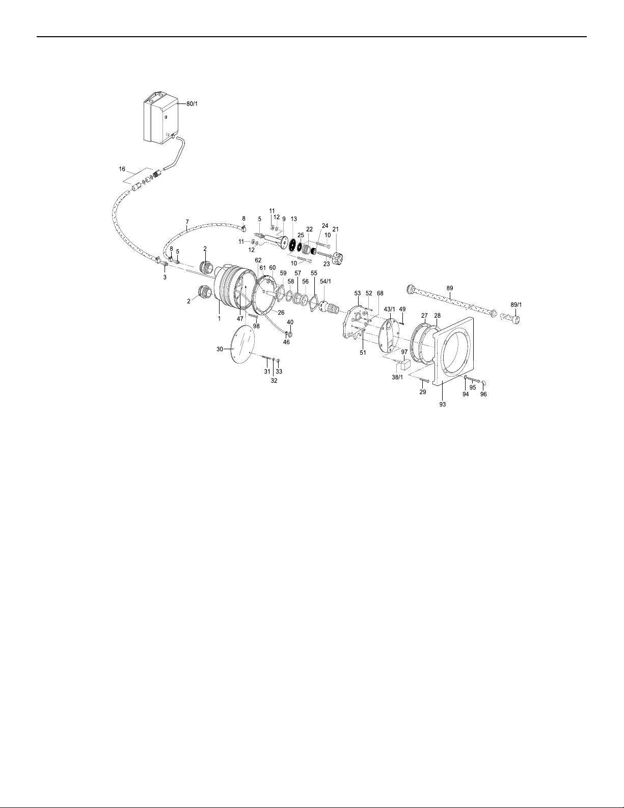
14. Parts List for the BADU®JET Classic
Part #
1
2
3
5
7
8
9
10
11
12
13
16
20
21
22
23
24
25
26
27
28
29
30
31
32
33
38/1
40
Qty
Description
1
Jet Housing
2
Adaptor - Male, Housing PVC 2” x 75mm/3”
1
Adaptor - Male, Housing PVC 1/2”
2
Nipple - Hose, Air Regulator, Plastic 1/4”
1
Hose - Air Regulator 8 x 3mm x 1.4 Meters
2
Clamp - Hose, Air Regulator 14/9 SS
1
Holder - Air Regulator
2
Bolt - Air Holder, Slot/Pan M6 x 30 SS
2
Nut - Air Holder Bolt M6, A2 SS
2
Washer - Air Holder
1
Gasket - Air Holder 60 x 11 x 2mm
1
Air Tubing Seal Assembly
1
Plug - Rubber 7mm
1
Top Part - Air Regulator
1
Bottom Part - Air Regulator
1
Bolt W/hole - Ar Regulator, Brass M10 x 80
1
Ring - Hose, Air Regulator 16 x 30 x 18mm
1
Gasket - Air Regulator 42 x 11 x 2mm
1
Gasket with Knobs - Jet Housing
1
Gasket - Clamping Ring
1
Ring - Clamping
10
Bolt - Clamping Ring, Slot/Barrel M6 x 25 A2
1
Cover - Gunite
4
Stud - Gunite Cover, All Thread, Zinc M6 x 80
4
Washer - Stud, Gunite Cover, Zinc M6
4
Nut - Stud, Gunite Cover M6 A2
1
Pneumatic Button (White)
1
Nut - Pneumatic Button, Plastic
Part #
43/1
46
47
49
51
52
53
54/1
55
56
57
58
59
60
61
62
68
80
89
89/1
93
94
95
95/1
96
97
98
Qty
Description
1
Cover - Nozzle
1
Clamp - Hose, Pneumatic Button 8.7mm
10M
Air Tube 4 x 1.5mm (per meter)
4
Tapping Screw - Nozzle Cover, Phillips 4.8 x 16 A2
5
Bolt - Nozzle Housing, Slot/Barrel M6 x 97mm A2
6
Bolt - Nozzle Housing, Slot/Barrel M6 x 25mm A2
1
Housing - Nozzle
1
Nozzle - Adjustable Flow 40mm
1
IT Gasket - Tension Cup 103 x 81.5 x 0.6mm
1
Seat - Nozzle
1
Spacer - Nozzle 6.2mm
1
Spacer - Nozzle 1.5mm
1
Tension Cup - Nozzle
4
Washer - Lock, Tension Cup M6 A4
4
Nut - Tension Cup M6 A2
1
O-Ring - Tension Cup 11 x 2.5mm
4
Bolt - Tension Cup, Phillips M6 x 25mm A2
1
Control Box BJC-7-GFCI
1
Massage Hose 5ft. with Pulsator
1
Massage Hose 15ft. with Pulsator (optional)
1
Cover - Rectangular
4
Washer - Rectangular Cover M6 A4
4
Bolt - Rectangular Cover, Pan, Phillips M6 x 16mm
4
Bolt - Rectangular Cover, Pan, Phillips M6 x 60mm
4
Plug - Rectangular Cover
1
Cover - Button
2
Bolt - Jet Housing, Slot/Pan M6 x 30mm SS
12
Page 15
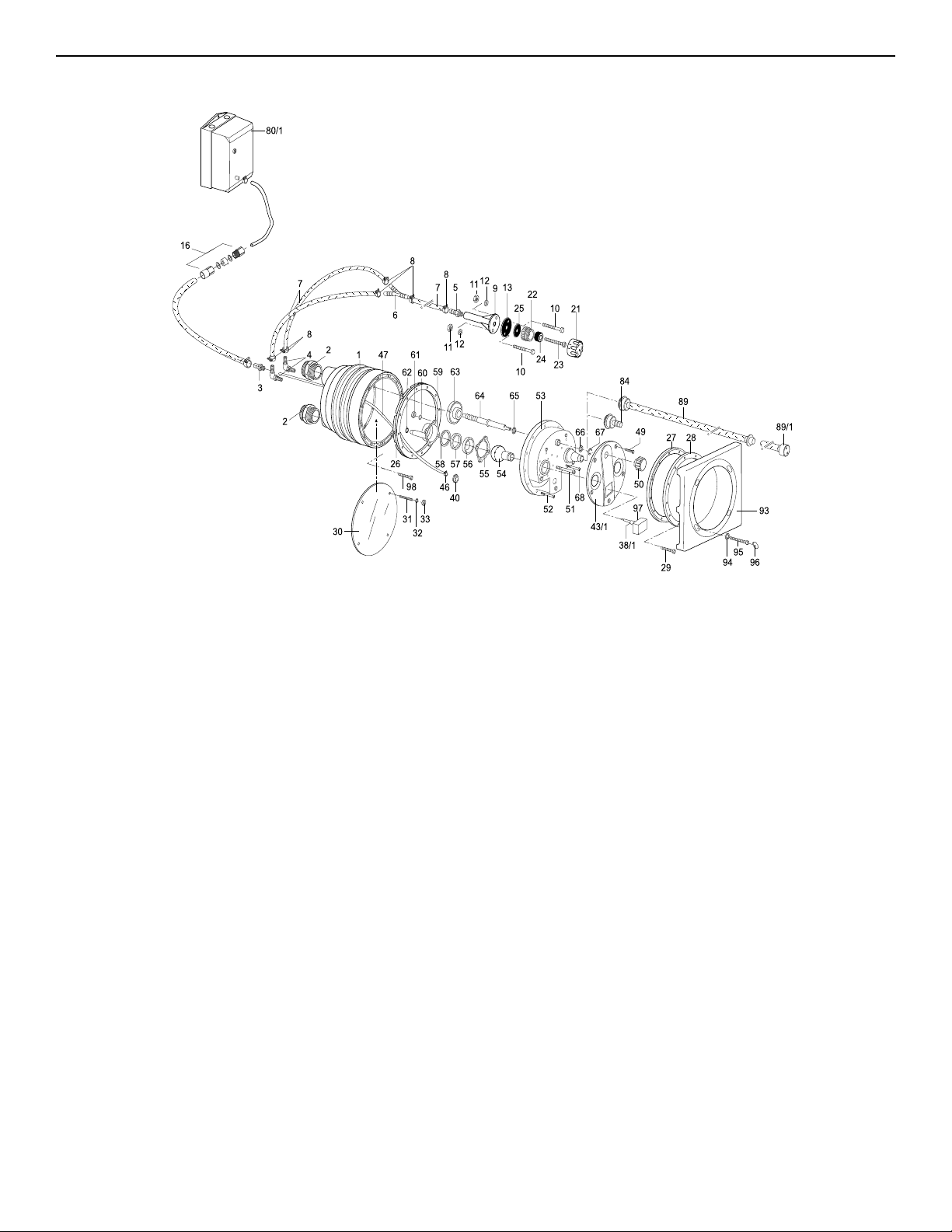
15. Parts List for the BADU®JET super-sport
Part #
1
2
2a
3
4
5
6
7
8
9
10
11
12
13
16
21
22
23
24
25
26
27
28
29
30
31
32
33
38/1
40
43/1
46
Qty
Description
1
Jet Housing
2
Adaptor - Male, PVC 2-1/2” x 90mm/4”
2
Coupling - Housing, PVC 110mm/4”
1
Adaptor - Male, Housing, PVC 1/2”
2
90o Hose Fitting - Air Regulator, Plastic 1/4”
1
Fitting - Hose, Air Regulator, Plastic 1/4”
1
Y-Fitting - Air Regulator
1
Hose - Air Regulator 8 x 3mm (1.4 meters)
6
Clamp - Hose Regulator 14/9 SS A4
1
Holder - Air Regulator
2
Bolt - Air Holder, Slot/Pan M6 x 30mm SS
2
Nut - Air Holder, M6, A2
2
Washer - Air Holder, M6, A4
1
Gasket - Air Holder 60 x 11 x 2mm
1
Air Tubing Seal Assembly
1
Top Part - Air Regulator
1
Bottom Part - Air Regulator
1
Bolt W/hole - Ar Regulator, Brass M10 x 80
1
Ring - Hose, Air Regulator 16 x 30 x 18mm
1
Gasket - Air Regulator 42 x 11 x 2mm
1
Gasket with Knobs - Jet Housing
1
Gasket - Clamping Ring
1
Ring - Clamping
12
Bolt - Clamping Ring, Slot/Barrel M8 x 30 A4
1
Cover - Gunite
4
Stud - Gunite Cover, All Thread, Zinc M8 x 80
4
Washer - Gunite Cover, Zinc M8
4
Nut - Stud, Gunite Cover M8 A2
1
Pneumatic Button (White)
1
Nut - Pneumatic Button, Plastic
1
Cover - Nozzle
1
Clamp - Hose, Pneumatic Button 8.7mm
Part #
47
49
50
51
52
53
54
55
56
57
58
59
60
61
62
63
64
65
67
68
80/1
84
89
89/1
93
94
95
95/1
96
97
98
Qty
Description
10M
Air Tube 4 x 1.5mm (per meter)
5
Tapping Screw - Nozzle Cover, Phil. 4.8 x 19 A4
1
Volume Control Knob
10
Bolt - Nozzle Housing, Slot/Barrel M8 x 130 A2
12
Bolt - Nozzle Housing, Phillips/Barrel M8 x 30 A2
1
Housing - Nozzle
2
Nozzle - 40mm
2
IT Gasket - Tension Cup 103 x 81.5 x 0.6mm
2
Seat - Nozzle
2
Spacer - Nozzle 6.2 mm
2
Spacer - Nozzle 1.0mm
2
Tension Cup - Nozzle
8
Washer - Lock, Tension Cup M6 A2
8
Nut - Tension Cup M6 A2
O-Ring - Tension Cup 11 x 2.5mm
2
Volume Control Disc
1
Control Spindle
1
Washer - Control Spindle, 23 x 16.2 x 1.5mm
1
Retainer - Shaft, Control Spindle
2
Bolt - Tension Cup, Phillips M6 x 25 A2
8
Control Box BJC-7-GFCI
1
Cap - Nozzle, Close off
1
Massage Hose 5ft. with Pulsator
1
Massage Hose 15ft. with Pulsator (optional)
1
Cover - Rectangular
1
Washer - Rectangular Cover M8 A2
4
Bolt - Rectangular Cover, Phillips M8 x 20mm
4
Bolt - Rectangular Cover, Phillips M8 x 80mm
4
Plug - Rectangular Cover
4
Cover - Button
1
Bolt - Jet Housing, Slot/Pan M8 x 30mm A4
2
13
Page 16
16. Limited Warranty
The manufacturer supplies a limited warranty to the original consumer purchaser of the BADUJET on the follow-
ing terms and conditions:
1. The BADUJET is warranted to be free from defects
in material and workmanship for a period of twelve (12)
months from the date that the BADUJET is originally
installed.
2. Not withstanding any provisions herein to the contrary,
the warranties and obligations hereunder shall not in any
event extend for more than 2 years beyond the date of
shipment of the BADUJET from Speck Pumps - Pool
Products, Inc. in Jacksonville, Florida.
3. Warranty is void in the following cases: damages which
result in whole or in part from: (a) careless or improper
installation of the BADUJET; (b) improper or negligent
use and maintenance of the BADUJET; (c) tampering
with the BADUJET by unauthorized repair personnel;
(d) ground movement; (e) substitution of parts and/or
components.
4. The manufacturer’s sole obligation here under shall
be to replace or repair any defective BADUJET. The
manufacturer reserves the absolute right to determine
whether any defective BADUJET should be replaced or
repaired.
5. Any customer who wishes to make a claim under this
Limited Warranty shall notify Speck Pumps, of such claim
by telephone or by mail. After the customer has been au-
thorized to return the BADUJET, the customer must return the BADUJET to Speck Pumps.
Any goods returned to Speck Pumps without prior authorization will be returned to the shipper unopened. Speck
Pumps shall not bear any costs or risks incurred in ship-
ping a defective BADUJET to Speck Pumps or in shipping a repaired or replaced BADUJET to a customer.
6. Speck Pumps will charge customers for all non warranty work which it may perform. Warranty work will not
be performed until the customer has accepted the price
quoted.
7. Except as specically set forth above, no other war-
ranties, whether express or implied, including without
limitation, the implied warranties of merchantability
and tness for a particular purpose, are made by the
manufacturer. In no event will the manufacturer be
liable for any loss, including time, money, goodwill,
lost prots and consequential damages based on
contrast, tort or other legal theory, which may arise
hereunder or from the use, operation of modication
of the pump, motor or associated parts. The maximum liability of the manufacturer hereunder shall not
exceed the amount actually paid by the customer for
the pump, motor and associated parts.
8. Some states do not permit limitations on the terms
of implied warranties or on the recovery of incidental or
consequential damages. Accordingly, the limitations contained in paragraph 7, may not apply to certain customers.
9. This warranty gives customers specic legal rights
which may vary from state to state. The BADUJET is
manufactured under license from Speck Pumpen, GERMANY.
Date of Installation:
Installed By:
Serial Numbers:
For Service Call:
3.HP.RT
SAVE THESE INSTRUCTIONS!
8125 Bayberry Road
Jacksonville, Florida 32256 USA
Phone (904) 739-2626 Fax (904) 737-5261
e-mail: [email protected]
website: www.usa.speck-pumps.com
 Loading...