

Page 1
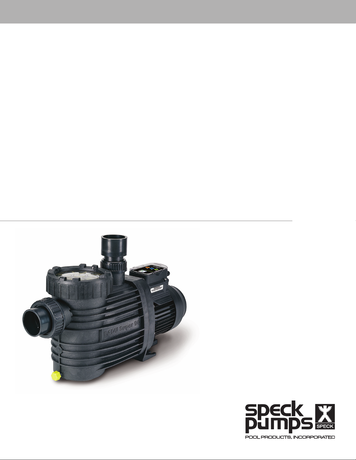
Installation, Operating,
and Service Manual
Badu® EcoM3V
Variable Speed Pool Pump
Page 2

Technical Support
Address: Speck Pumps
8125 Bayberry Road
Jacksonville, FL. 32256
USA
Hours: (Monday - Friday) 8:00 am to 5:00 pm EST
Toll Free: 800-223-8538
Phone: 904-739-2626
Fax: 904-737-5261
Website: www.usa.speck-pumps.com
Manufactured by Speck Pumps, Jacksonville Florida USA, © 2012 All Rights Reserved.
This document is subject to change without notice.
Date of Installation:
Installed By:
Serial Number:
For Service Call:
2999999995 - Rev 05/2012
SAVE THESE INSTRUCTIONS!
Page 3

Table of Contents
1 Important Safety Instructions 4
2 General Description 6
3 Installation Information 7
Preparation Guide . . . . . . . . . . . . . . . 7
Pump Location . . . . . . . . . . . . . . . . 8
Pipe Sizing . . . . . . . . . . . . . . . . . . 8
Plumbing Installation . . . . . . . . . . . . . . 8
Bonding and Grounding . . . . . . . . . . . . . 10
Electrical Installation . . . . . . . . . . . . . . 10
Voltage Checks . . . . . . . . . . . . . . . . 11
Pressure Testing . . . . . . . . . . . . . . . . 11
4 Operation 12
Start-Up Guide . . . . . . . . . . . . . . . . 12
Changing the Default Speed . . . . . . . . . . . 13
Adjusting the Speed . . . . . . . . . . . . . . 14
5 Service and Maintenance 15
Routine Maintenance . . . . . . . . . . . . . . 15
Winterizing . . . . . . . . . . . . . . . . . . 16
6 Troubleshooting 16
Controller Malfunction Warnings. . . . . . . . . . 16
General Troubleshooting Problems . . . . . . . . 17
Blocked Impeller . . . . . . . . . . . . . . . . 18
Removal and Replacement of the Impeller . . . . . 18
Mechanical Seal Replacement . . . . . . . . . . 18
Motor Replacement . . . . . . . . . . . . . . 19
7 Product Specications 20
Replacement Parts and Exploded View . . . . . . . 20
Performance Curves . . . . . . . . . . . . . . 21
8 Limited Warranty 21
Page 4

1 Important Safety Instructions
READ THIS MANUAL CAREFULLY BEFORE USING THE SPECK PUMP
READ AND FOLLOW ALL INSTRUCTIONS!
Important Notice:
This manual contains important information about the installation, operation and safe use of this product.
This information should be given to the owner and/or operator of this equipment.
WARNING: Before Installing this product, read and follow all warning notices and instructions which
are included. Failure to follow safety warnings and instructions can result in severe injury, death, or
property damage. Call 1-800-223-8538 or visit www.usa.speck-pumps.com for additional copies of these
instructions.
WARNING - Entrapment Prevention
DANGER: DO NOT BLOCK SUCTION
SUCTION HAZARD. Can cause serious injury or death. Do not use
this pump for wading pools, shallow pools, or spas containing bottom
drains, unless pump is connected to at least two (2) functioning suction
outlets.
WARNING: Pump suction is hazardous and can trap and drown or
disembowel bathers. Do not use or operate swimming pools, spas, or
hot tubs if a suction outlet cover is missing, broken, or loose.
The following guidelines provide information for pump installation
that minimizes risk of injury to users of pools, spas, and hot tubs:
Entrapment Protection: The pump suction system must provide
protection against the hazards of suction entrapment.
Suction Outlet Covers: All suction outlets must have correctly installed,
screw-fastened covers in place. All suction outlet (drain) covers must be
maintained. Drain covers must be listed/certied to the latest published
edition of ANSI/ASME A112.19.8 (ANSI/APSP-16, 2011). They must be
replaced if cracked, broken, or missing.
Number of Suction Outlets Per Pump: Provide at least two (2)
hydraulically-balanced main drains, with covers, as suction for each
circulating pump suction line. The centers of the main drains (suction
outlets) on any one (1) suction line must be at least three (3) feet apart,
center to center.
4
Page 5
The system must be built to include at least two (2) suction outlets (drains) connected to the pump
whenever the pump is running. However, if two (2) main drains run into a single suction line, the single
suction line may be equipped with a valve that will shut off both main drains from the pump. The system
shall be constructed such that it shall not allow for separate or independent shutoff or isolation of each
drain.
More than one (1) pump can be connected to a single suction line as long as the requirements above are
met.
Water Velocity: The maximum water velocity through the suction tting or cover for any suction outlet
must be 1.5 feet per second, unless the outlet complies with the latest published edition of ANSI/ASME
A112.19.8 (ANSI/APSP-16, 2011), the standard for Suction Fittings For Use in Swimming and Wading
Pools, Spas, Hot Tubs, and Whirlpool Bathtub Applications. In any case, do not exceed the suction if
tting’s maximum designed ow rate.
If 100% of the pump’s ow comes from the main drain system, the maximum water velocity in the pump
suction hydraulic system must be six (6) feet per second or less, even if one (1) main drain (suction
outlet) is completely blocked. The ow through the remaining main drain(s) must comply with the latest
published edition of ANSI/ASME A112.19.8 (ANSI/APSP-16, 2011), the standard for Suction Fittings For
Use in Swimming and Wading Pools, Spas, Hot Tubs, and Whirlpool Bathtub Applications.
Testing and Certication: Suction outlet covers must have been tested by a nationally recognized
testing laboratory and found to comply with the latest published edition of ANSI/ASME A112.19.8 (ANSI/
APSP-16, 2011), the standard for Suction Fittings For Use in Swimming and Wading Pools, Spas, Hot
Tubs, and Whirlpool Bathtub Applications.
Fittings: Fittings restrict ow; for best efciency use fewest possible ttings (but at least two (2) suction
outlets).
Avoid ttings that could cause an air trap.
Pool cleaner suction ttings must conform to applicable International Association of Plumbing and
Mechanical Ofcials (IAPMO) standards.
WARNING - Risk of Electrical Shock or Electrocution
This pool pump must be installed by a licensed or certied electrician or
a qualied pool serviceman in accordance with the National Electrical
Code and all applicable local codes and ordinances. Improper installation
will create an electric hazard which could result in death or serious injury
to pool users, installers, or others due to electrical shock, and may also
cause damage to property.
Always disconnect power to the pool pump at the circuit breaker
before servicing the pump. Failure to do so could result in death or
serious injury to serviceman, pool users, or others due to electric shock.
5
Page 6

Important Safety Instructions
When installing and using this electrical equipment, basic safety precautions should always be
followed, including the following:
READ AND FOLLOW ALL INSTRUCTIONS
WARNING: To reduce the risk of injury, do not permit children to use this product unless they are closely
supervised at all times.
WARNING: Risk of Electrical Shock. Connect only to a grounding type receptacle protected by a groundfault circuit-interrupter (GFCI). Contact a qualied electrician if you cannot verify that the receptacle is
protected by a GFCI.
The unit must be connected only to a supply circuit that is protected by a ground-fault circuit-interrupter
(GFCI). Such a GFCI should be provided by the installer and should be tested on a routine basis. To test
the GFCI, push the test button. The GFCI should interrupt power. Push the reset button. Power should be
restored. If the GFCI fails to operate in this manner, the GFCI is defective. If the GFCI interrupts power to
the pump without the test button being pushed, a ground current is owing, indicating the possibility of an
electric shock. Do not use this pump. Disconnect the pump and have the problem corrected by a qualied
service representative before using.
CAUTION: This pump is for use with permanently installed pools and may also be used with hot tubs
and spas if so marked. Do not use with storable pools. A permanently installed pool is constructed in or
on the ground or in a building such that it cannot be readily disassembled for storage. A storable pool is
constructed so that it may be readily disassembled for storage and reassembled to its original integrity.
TO REDUCE THE RISK OF ELECTRICAL SHOCK, connect ground wires to grounding screw located in
the motor. Use no smaller than a #12 AWG (3.3mm2) wire.
TO REDUCE THE RISK OF ELECTRICAL SHOCK, a bonding connector is provided for bonding to
metal water pipes, metal rails, or other metal within 5 feet of the swimming pool. All local points should be
bonded with a #8 AWG (8.4mm2) wire.
SAVE THESE INSTRUCTIONS.
2 General Description
Badu EcoM3 - Variable Speed
The Badu EcoM3 - Variable Speed swimming pool pump is both environment friendly and cost efcient.
This revolutionary three speed pump provides the pool owner a simple three button control to operate
the pump, greatly reducing the operating cost at a reasonable investment. The robust pump is based on
Speck Pumps energy efcient design platform. The Badu EcoM3 - Variable Speed high performance,
medium head pump uses a state of the art axial ux permanent magnet brushless-DC motor controlled
by advance logic electronics. Providing cooler and quieter operation at a fraction of the cost of a standard
PSC motor.
6
Page 7
General Description - continued
The afnity laws of hydraulics states that if you half the speed, the power reduces by 8 times. The multiple
speeds offered by the Badu EcoM3 - Variable Speed enables it to run slower and consume less energy
but still have the ability to run at full speed if required.
The Badu EcoM3 - Variable Speed operates at a maximum system ow of 100 gallons per minute (GPM)
at 3450 RPM.
This pump can operate from 1000 RPM to 3450 RPM with factory preset speeds of 1600, 2600, and
3450 RPM. This allows you to select the most appropriate speed for your application. The Badu EcoM3 Variable Speed pump was designed to meet the needs of today’s more environmentally friendly consumer.
The pump parts are made of 100% recyclable “environment friendly“ plastic. The axial ux brushless-DC
motor, has a signicant reduction in greenhouse gas emissions, saving greater than 2 tonne CO2 per
year. Lower noise reduction, and energy savings per year.
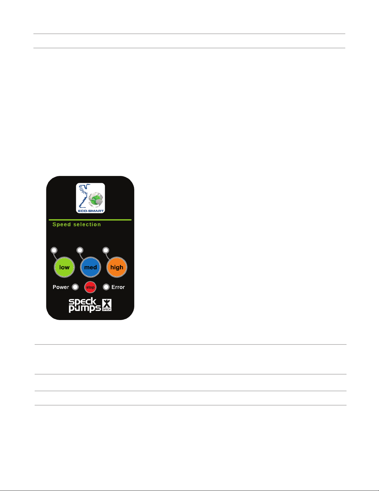
The Badu EcoM3 - Variable Speed control panel provides
manual speed controls for the pump. There are three preset
speed buttons that can be selected LOW, MEDIUM, and
HIGH.
Controls and LEDs
1. LOW, MED, and HIGH buttons/LED: Press one of the
buttons to select the desired factory preset pump speed. The
pump factory preset speeds are: LOW (1600 RPM), MED
(2600 RPM), and HIGH (3450 RPM). The button’s green
LED is on when the selected button is pressed.
2. Power LED: This green LED light is on when the Badu
EcoM3 - Variable Speed pump is powered up.
3. Error LED: This red LED is on whenever an error has
occurred.
4. STOP button: Press to stop the pump.
WARNING: STOP button will turn off the pump but voltage is
Figure 1
still present. Always turn OFF the breaker before servicing.
3 Installation Information
Preparation Guide
1. Upon receipt of the pump, check the carton for damage. Open the carton and check the pump for
concealed damage, such as cracks, dents, or a broken base. If damage is found, contact the shipper or
distributor where the pump was purchased.
2. Inspect the contents of the carton and verify that all parts are included. See Section 7, Parts List and
Exploded View for details.
7
Page 8

Pump Location
NOTE: In Canada, the pump must be located a minimum of three (3) meters (approximately ten
(10) feet) from the water (CSA C22.1).
1. Speck Pumps recommends in order to achieve better self-priming, to install the pump as close to the
pool as practical. Consult local codes for minimum distance between pool and pump.
WARNING: Some Safety Vacuum Release System (SVRS) devices are not compatible with
the installation of check valves. If the pool has an SVRS device, be sure to conrm that it will
continue to safely operate when the check valves are installed.
2. The piping should be as direct and free from turns or bends as possible, as elbows and others ttings
greatly increase friction losses.
3. Place pump on solid foundation which provides a rigid and vibration-free support so that it is readily
accessible for service and maintenance.
4. Protect the pump against ooding and excess moisture, and prevent foreign objects from clogging
air circulation around motor. All motors generate heat that must be removed by providing proper
ventilation.
5. DO NOT store or use gasoline or other ammable vapors or liquids in the vicinity of this pump. DO
NOT store pool chemicals near the pump.
6. DO NOT remove any safety alert labels such as DANGER, WARNING, or CAUTION. Keep safety
labels in good condition and replace any missing or damaged labels.
7. Provide access for future services by leaving a clear area around the pump. Allow plenty of space
above the pump to remove lid and basket for cleaning.
8. Install the pump in a well ventilated location protected from direct sunlight and excessive moisture.
(rain, sprinklers, etc.)
Pipe Sizing
NOTE: All pipe sizes are able to withstand the pressures the pump will deliver, but not
necessarily the ow. If the pipe is too small for the pump, or is elevated above water, the
maximum gallons per minute (GPM) may not be delivered. If this happens, the pump will
develop a pocket of air (cavitation) that makes noise. This may shorten the life of the pump.
SUCTION & DISCHARGE:
When the pump is located up to 50 feet from the pool, the recommended minimum pipe size for both
the suction and discharge is 2”.
Plumbing Installation
When installing the pump, care should be taken to see the suction line is below water level to a point
immediately beneath the pump to ensure quick priming via a ooded suction line. The height between
the pump and water level should not be more than ve (5) feet.
8
Page 9

Plumbing Installation - continued
If the pump is located below water level, isolation valves must be installed on both sides of the pump to
prevent the back ow of pool water during any routine or required servicing. The Badu EcoM3 - Variable
Speed comes equipped with unions on both the suction and discharge ports. This feature simplies
installation and service and eliminates the possibility of leaks at the threaded adaptors.
Before starting the pump for the rst time, remove the see-through lid. (Turn lid counter clockwise to
remove.) Fill strainer tank with water until it is level with the suction inlet. Replace lid, making sure the
o-ring is not damaged. Screw down, hand tight.
Suction and discharge line should be independently supported at a point near the pump to avoid strains
being placed on the pump. Always use properly sized valves.
Use the fewest ttings as possible. Each additional tting has the effect of moving the equipment farther
away from the water.
NOTE: If more than ten (10) suction ttings are needed, the pipe size must be increased.
Every new installation must be pressure tested according to local codes. See the Pressure Testing
Section on page 7
Bonding and Grounding
When installing and using the motor, basic safety precautions should always be followed. The wiring of
the motor should be done by a licensed electrician in accordance with local codes.
BONDING AND GROUNDING
1. The motor frame must be grounded to a reliable grounding point using a solid copper conductor,
No. 8 AWG or larger. In Canada, No. 6 AWG or larger must be used. If the pump is installed within ve
(5) feet of the inside walls of the swimming pool, spa, or hot tub, the motor frame must be bonded to
all metal parts of the swimming pool, spa, or hot tub structure and to all electrical equipment, metal
conduit, and metal piping within ve (5) feet of the inside walls of the swimming pool, spa, or hot tub.
2. Bond the motor using the provided external lug.
WARNING: Always disconnect the power source before working on a motor or its connected
load.
WARNING: In order to avoid the risk of property damage, severe personal injury, and/or death,
make sure that the control switch, time clock, or control system is installed in an accessible
location, so that in the event of an equipment failure or loose plumbing tting, the equipment
can be easily turned off.
CAUTION: The pump must be permanently connected to a dedicated electrical circuit. No
other equipment, lights, appliances, or outlets may be connected to the pump circuit, with the
exception of devices that may be required to operate simultaneously with the pump, such as a
chlorinating device or heater.
WARNING: Motor is tted with internal auto reset. May restart without warning!
9
Page 10

Electrical Installation
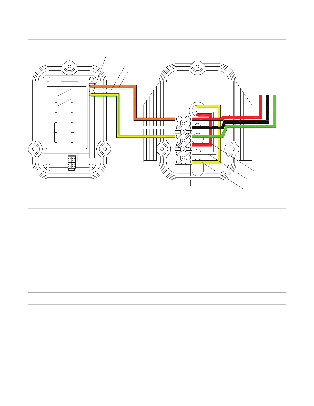
1. The pump motor must be securely grounded inside the motor control box. (See Figure 2.0)
NOTE: Do not connect to electric power supply until unit is permanently grounded.
2. Wire size must be adequate to minimize voltage drop during the start-up and operation of the pump.
See Table 1.0 for recommended wiring sizes.
3. Insulate all connections carefully to prevent grounding or short-circuits. Sharp edges on terminals
require extra protection. To prevent the wire nuts from loosening, tape them using suitable, listed (UL,
ETL, CSA) electrical insulating tape. For safety, and to prevent entry of contaminants, reinstall all
conduit and terminal box covers. Do not force connections into the conduit box.
Table 1.0
Recommended Wire Sizes for the Badu EcoM3 - Variable Speed
Recommended Wire Sizes For The Badu EcoM3 - Variable Speed
Distance from Sub-panel 0 - 50 Feet 50 - 100 Feet 100 - 150 Feet
Voltage 208 - 230 VAC 208 - 230 VAC 208 - 230 VAC
Minimum Wire Size 12 10 8
1. Remove the three screws holding the top control enclosure onto the motor. Carefully lift the top panel
and turn it over to expose the inside terminal box. See Figure 2
2. The terminal box is supplied with a 1/2” -14 NPS threaded hole. Use only liquid tight ttings in order
to protect the electronics and the motor.
CAUTION: Failure to use liquid tight ttings will void the warranty.
3. The right side of the terminal block will be marked ground, L2, and L1. See Figure 2
4. After running L1, L2, and ground wire from conduit, connect the L1 to the opening directly across
from the orange wire on the terminal block. See Figure 2
5. Connect L2 to the opening directly across from the white wire on the terminal block. See Figure 2
6. Connect the ground wire to the opening directly across from the green/yellow wire on the terminal
block. See Figure 2
7. Carefully fold all wires inside the terminal box and place the top control panel back on top of the
terminal box.
8. Tighten the three screws into the terminal box while applying light pressure to the top control enclosure.
DO NOT OVER TIGHTEN.
9. The Badu EcoM3 - Variable Speed is a 208-230 volt pump. Make sure the correct voltage is supplied
(refer to the motor plate). Note: If the motor exceeds 250 volts the pump will not start from the Off/Stop
position.
10
Page 11
Electrical Installation - continued
Green\Yellow
Org
Wht
Green/
Yellow
L 1
L 2
Ground
Red
White
Orange
Connection
Control Box
Lower Half
Line 1
Line 2
Ground
White
Control
Yellow
Motor
Red
Connection
Control Box
Top Half
Figure 2
White
Yellow
Voltage Checks
The correct voltage, as specied on the pump data plate, is necessary for proper performance and long
motor life. Incorrect voltage will cause the error light to turn on and cause damage to the motor if not
turned off immediately.
It is the responsibility of the electrical installer to provide data plate operating voltage to the pump by
ensuring proper circuit sizes and wire sizes for this specic application.
CAUTION: Failure to provide data plate voltage during operation will cause the motor to
overheat and void the warranty.
Pressure Test
WARNING: When pressure testing a system with water, air is often trapped in the system during
the lling process. This air will compress when the system is pressurized. Should the system
fail, this trapped air can propel debris at a high speed and cause injury. Every effort to remove
trapped air must be taken, including opening the bleed valve on the lter and loosening the
pump basket lid while lling the pump.
WARNING: Trapped air in the system can cause the lter lid to be blown off, which can result in
death, serious injury, or property damage. Be sure all air is properly purged out of the system
before operating. DO NOT USE COMPRESSED AIR TO PRESSURE TEST OR CHECK FOR
LEAKS.
11
Page 12

Pressure Test - continued
WARNING: When pressure testing the system with water, it is very important to make sure that
the pump basket and lid is completely secure.
STEPS:
1. Fill the system with water, using care to eliminate trapped air.
2. Pressurize the system with water to no more than 35 PSI.
WARNING: Do not pressure test above 35 PSI. Pressure testing must be done by a trained pool
professional. Circulation equipment that is not tested properly might fail, which would result in
severe injury or property damage.
3. Close the valve to trap pressurized water in the system.
4. Observe the system for leaks and/or pressure decay.
5. If there are leaks, repeat Steps 1 -3. For technical support, call 1-800-223-8538.
4 Operation
Start Up Guide
CAUTION: Never run the pump without water. Running the pump “dry“ for any length of time can
cause severe damage to both the pump and the motor and will void the warranty.
If this is a new pool installation, make sure all piping is clear of construction debris and has been properly
pressure tested. The lter should be checked for proper installation, verifying that all connections and
clamps are secure according to the manufacturer’s recommendations.
WARNING: To avoid risk of property damage, severe personal injury or death, verify that all power
is turned off before starting this procedure.
1. Release all pressure from the system and open the lter pressure release valve.
2. Depending on the location of the pump, do one of the following:
- If the pump is located below the water level of the pool, open the lter pressure valve to prime the pump
with water.
- If the pump is located above the water level of the pool, remove the lid and ll the basket with water
before starting the pump.
3. Prior to replacing the lid, check for debris around the lid o-ring seat. Debris around the lid o-ring seat
will make it difcult to prime the pump.
4. Hand-tighten the lid to make an air tight seal. Do not use any tools to tighten the lid: hand-tighten
only. Make sure all valves are open and the unions are tight.
5. Once all the air has left the lter, close the pressure release valve.
12
Page 13

Start Up Guide - continued
6. Switch on power to the pump-motor to start. There will be a delay of six to twelve (6 to 12) seconds as
the pump powers up.
7. The unit will automatically run on high speed for two (2) minutes to prime the pump. After the two
minutes the pump will default to low speed. Note: When you press the medium or high button after the
two (2) minute priming, the pump will then run for two (2) hours on the speed you selected then default
back to low. If full prime has not been achieved after initial 2 minute prime cycle, rell the pump with water
and start on High speed and allow pump to run on High speed for up to 5 minutes to allow air trapped in
the suction line to be purged.
8. The pump has three (3) speed settings - low, medium, and high.
High:
Medium:
Used when vacuuming the pool or
operating the spa jets or some water
features such as water falls.
Used for gentle spa jet action, or ltration
SPEED LOW MEDIUM HIGH
Default 1600 2600 3450
MAXIMUM 1725 2800 3450
MINIMUM 1000 1800 2850
for the pool.
Low:
Recommended for everyday ltration of
your pool. (This speed will achieve the
lowest operating costs with the lowest
noise level.)
9. If the power is turned off or the pump is stopped, it will repeat this process. (See number 6 & 7)
10. If the pump does not prime and all the instructions to this point have been followed, check for a
suction leak. If there is a leak repeat Steps 2 through 6.
11. For technical assistance, call Speck Pumps Technical Support at 800-223-8538.
Changing the Default Speed
The pump is factory set with a default speed of LOW. However, it can be modied to medium speed as
required by minimum ow pressure requirements of various pool side equipment/features as dened by
the manufacturer specications. The default speed should be modied during the rst two minutes of
applying power to the unit.
Please follow all local/state regulations regarding pool motor and timer speeds settings when
choosing the default speed.
1. Allow the pump to achieve prime if starting the system for the rst time.
2. Turn the power off using the off button on the controller once prime is reached. Allow the pump to sit in
the off position for at least 30 seconds.
3. Turn the pump on and allow the motor to come to full speed.
4. Press and hold the high and medium buttons simultaneously until the low speed LED indicator light
begins to blink and then release.
13
Page 14

Changing the Default Speed - continued
5. The low speed LED will continue to blink for three seconds to indicate a modication to the automatic
default speed is being requested. After a brief pause, a second series of LED blinks will indicate the new
default setting has been set to either medium speed (medium speed LED blinks) or low speed (low speed
LED blinks).
Adjusting the Speeds
The Badu EcoM3 - Variable Speed pump control panel provides manual speed controls for the pump.
There are three (3) factory preset buttons that can be selected (LOW, MED, or HIGH). The LOW button
is preset to 1600 RPM. The MED button is preset to 2600 RPM. The HIGH button is preset to 3450
RPM. Once a button (LOW, MED, or HIGH) is pressed the LED for the appropriate button will appear.
However, the three (3) speeds can be modied to various speeds required by minimum ow pressure
requirements of various pool side equipment/features as dened by the manufacturer specications.
Please follow all local/state regulations regarding pool motor and timer speeds settings when
choosing the appropriate speeds.
To Adjust LOW Speed
• Verify that the pump is powered ON and the green power LED light is on.
• Press the LOW button for 5 to 10 seconds, this will switch the control from Normal Operation Mode
to the Speed Adjust Mode. The LOW LED light will begin to blink.
• Press the left (LOW) button to decrease the speed.
or
• Press the right (HIGH) button to increase the speed.
(NOTE: The button will increase or decrease in increments of 200 RPM, in most cases. The
Speed Range for Low Speed is 1000, 1200, 1400, 1600, 1725. Factory Preset is 1600.)
• Press the middle (MED) button to save the current the speed and return to Normal Operation Mode.
• To Stop or Exit out of Speed Adjust Mode, Press the STOP button or wait 30 seconds without pressing
any buttons. NOTE: If the power is shut off or the pump is stopped using the stop button, upon
powering up the pump will run a two (2) minute prime on HIGH and then resume normal operation.
DO NOT press any buttons during prime operation.
To Adjust the MEDIUM Speed
• Verify that the pump is powered ON and the green power LED light is on.
• Press the MED button for 5 to 10 seconds, this will switch the control from Normal Operation Mode to
the Speed Adjust Mode. The MED LED light will begin to blink.
• Press the left (LOW) button to decrease the speed.
or
• Press the right (HIGH) button to increase the speed.
(NOTE: The button will increase or decrease in increments of 200 RPM, in most cases. The Speed
Range for Medium Speed is 1800, 2000, 2200, 2400, 2600, 2800. Factory Preset is 2600.)
• Press the middle (MED) button to save the current the speed and return to Normal Operation Mode.
• To Stop or Exit out of Speed Adjust Mode, Press the STOP button or wait 30 seconds without pressing
any buttons. NOTE: If the power is shut off or the pump is stopped using the stop button, upon
powering up the pump will run a two (2) minute prime on HIGH and then resume normal operation.
DO NOT press any buttons during prime operation.
14
Page 15

Adjusting the Speeds - continued
To Adjust the HIGH Speed
• Verify that the pump is powered ON and the green power LED light is on.
• Press the HIGH button for 5 to 10 seconds, this will switch the control from Normal Operation Mode
to the Speed Adjust Mode. The HIGH LED light will begin to blink.
• Press the left (LOW) button to decrease the speed.
or
• Press the right (HIGH) button to increase the speed
(NOTE: The button will increase or decrease in increments of 200 RPM, in most cases. The
Speed Range for HIGH Speed is 2850, 3050, 3250, 3450. Factory Preset is 3450.)
• Press the middle (MED) button to save the current the speed and return to Normal Operation Mode.
• To Stop or Exit out of Speed Adjust Mode, Press the STOP button or wait 30 seconds without pressing
any buttons. NOTE: If the power is shut off or the pump is stopped using the stop button, upon
powering up the pump will run a two (2) minute prime on HIGH and then resume normal operation.
DO NOT press any buttons during prime operation.
Adjusting Back to Factory Settings
• Verify that the pump is powered ON and the green power LED light is on.
• Press and Hold all three (3) speed buttons (LOW, MED, and HIGH) for 5 to 10 seconds.
• All LED light will be fully lit. The LED’s will blink to indicate the factory defaults were re-established.
5 Service and Maintenance
Routine Maintenance
This pump requires little or no service other than reasonable care and periodic cleaning of the strainer
basket.
1. Inspect the pump basket for debris by looking through the clear pump lid.
2. Turn off the power to the pump. If the pump is located below the water level, close isolation valves on
the suction and discharge sides of the pump to prevent back ow of water.
3. Remove any debris, because as the debris accumulates, it will begin to block the ow of water
through the pump. Keep the basket clean and clear to improve the performance of the pump.
4. Turn the lid’s lock ring counter clockwise until it stops. Carefully remove the lid and lock ring.
5. Remove the basket and properly dispose of the debris into the trash and rinse out the basket. Check
basket for cracks, if crack is found replace basket.
6. Replace basket back into the pump, align the basket properly with the suction pipe. Then ll with
water up to the suction pipe. Clean clear cover, lid o-ring and sealing surface of the pump of any debris.
7. Replace lid with locking ring. Hand-tighten the lid to make an air-tight seal. Do not use any tools to
tighten the lid.
15
Page 16

Routine Maintenance - continued
8. Verify that all valves have been returned to the proper position for normal operation. Turn on the
power to the pump.
Winterizing
CAUTION: The pump must be protected when freezing temperatures are expected. Allowing the
pump to freeze will cause severe damage and void the warranty.
There are two options when winterizing the pump
Option 1:
1. Drain all the water from the pump, system equipment, and piping.
2. Remove drain plugs. Do not replace plugs. Store the plugs in the empty strainer basket for winter.
3. Keep the motor covered and dry.
Option 2:
1. Drain all the water from the pump, system equipment, and piping.
2. Remove the pump and motor from the plumbing and store indoors in a warm and dry location.
Note: When the winter season is over the pump will need to be primed prior to start. Refer to
Section 4 Operation, Start Up Guide.
CAUTION: DO NOT run the pump dry. If the pump is run dry, the mechanical seal will be damaged
and the pump will start to leak at the seal. If this occurs, the mechanical seal will need to be
replaced. ALWAYS maintain the proper water level in your pool. Continued operation in this
manner could cause a loss of pressure, resulting in damage to the pump casing, impeller, and
mechanical seal.
6 Troubleshooting
Controller Malfunction Warnings
WARNING: The pump must be serviced by a professional service technician qualied in pool/
spa installation. The following procedures must be followed exactly. Improper installation and/or
operation can create dangerous electrical hazards, which can cause high voltage to run through
the electrical system. This can cause property damage, serious personal injury, and/or death.
Improper installation and/or operation will void the warranty.
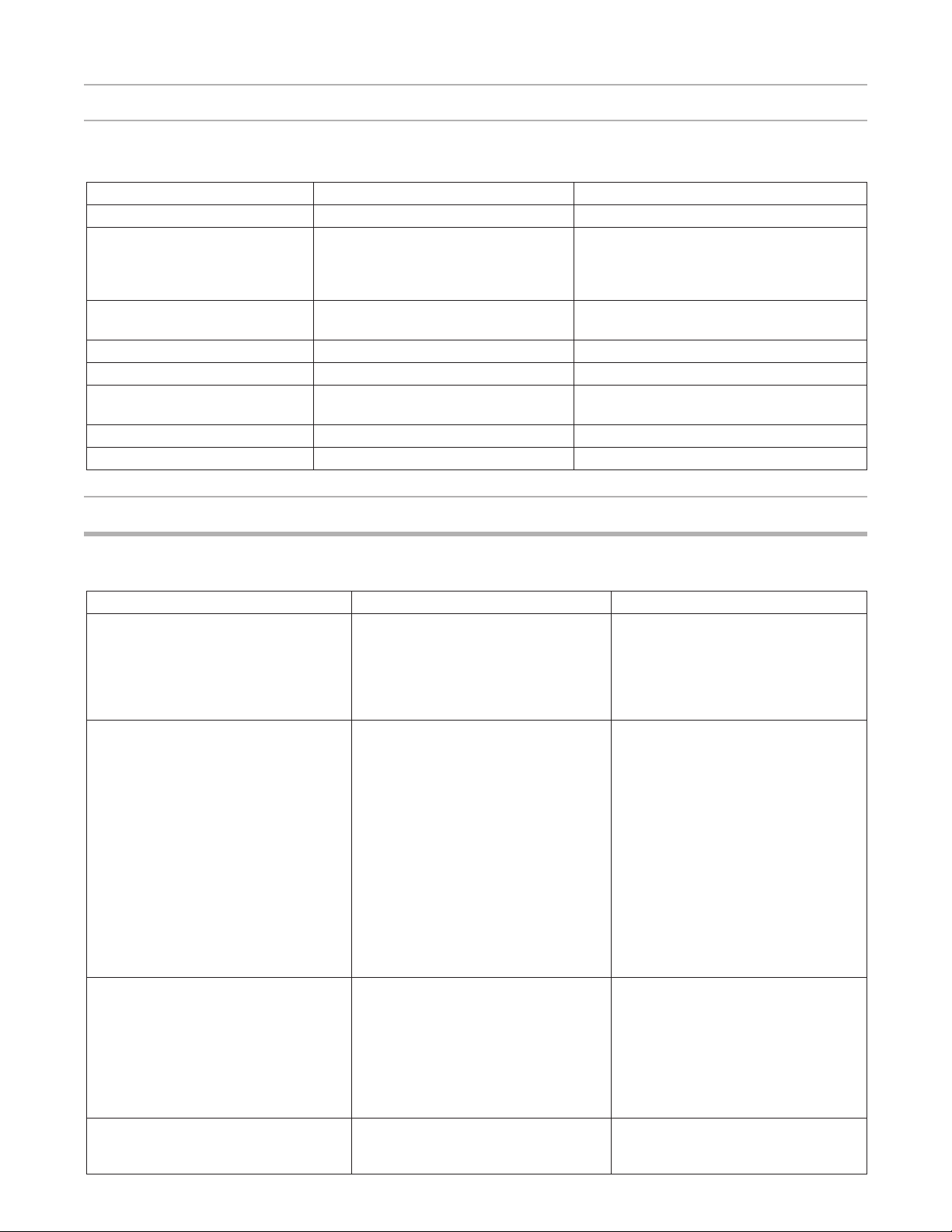
The Badu EcoM3 - Variable Speed malfunction warnings are indicated by a ashing LED light on the
control panel. If the error light is on pay attention to the appropriate number of ash intervals of short or
long duration, then shut the pump down immediately. For example, if a “Low Voltage” warning occurs,
the LED will blink two times, then off, then blink two times. This sequence is repeated until the condition
is cleared.
16
Page 17
Controller Malfunction Warnings - continued
Table 2.0
The Badu EcoM3 - Variable Speed Error Light Sequence
Flash Rate LED “Error” Light Error Description Cause
1 Flash Microprocessor fault Microprocessor Start-Up
2 Flashes Low voltage Voltage must exceed < 208V AC control
activates itself independently when voltage
exceeds 208V for more than six (6) seconds
(Motor Activates)
3 Flashes Temperature too high
Temperature too low
4 Flashes Thermal overload tripped Motor is drawing to many amps
5 Flashes High voltage Voltage has exceeded 269V AC
6 Flashes Shaft locked Impeller or pump locked/motor shaft stopped
7 Flashes Self-test One or more self-test were not completed
8 Flashes Motor Error One or more phases are not connected
Temperature Too High > 100
Temperature Too Low < -20o C (4o F)
turning
General Pump Troubleshooting
Table 3.0
The Badu EcoM3 - Variable Speed General Troubleshooting
o
C (212o F)
Problem Possible Cause Solution
1. Error Light appears during start-up A. Low Voltage During the initial start-up (6-12
seconds delay) there is a momentary
power drop, in which case the pump
will restart itself after the voltage
is above 208V for a period of six
seconds.
2. Pump will not prime. A. Suction air leak
B. No water in pump.
C. Closed valves or blocked lines.
D. Low voltage to motor.
3. Motor does not turn A. No power to motor.
Make sure see-through lid and o-rings
are clean and properly positioned.
Hand tighten see-through lid. Tighten
all pipes and ttings on suction side
of pump. Be sure water in pool is high
enough to ow through skimmer.
Make sure strainer tank is full of water.
Open all valves in system. Clean
skimmer and strainer tank. Open pump
and check for clogging of impeller.
Check voltage at motor. If low, pump
will not come up to speed.
Check that all power switches are
on. Be sure fuse or circuit breaker is
properly set. Time set properly? Check
motor wiring at terminal.
B. Pump jammed
4. Low ow A. Dirty lter
B. Suction Leak
With power off, turn shaft. It should
spin freely. If not, disassemble and
repair.
Back wash lter when lter pressure is
high, or clean cartridges.
See Problem 2
17
Page 18
Blocked Impeller
WARNING: Before servicing the pump, switch off the circuit breakers at the power source. Severe
personal injury or death may occur if the pump starts while your hand is inside the pump.
1. Turn off the pump. Switch off the circuit breaker to the pump motor.
2. Remove the pump lid and strainer tank.
3. Look inside pump for debris. Remove any debris found inside.
4. Replace the strainer tank and lid.
5. Switch on the circuit breaker to the pump motor.
6. Turn on the pump, see if the problem is solved.
7. If the impeller is still blocked with debris and it is not possible to remove the debris using Steps 2 - 4,
the pump will need to be disassembled in order to access the inlet and outlet of the impeller.
Removal and Replacement of the Impeller and/or Mechanical Seal
WARNING: Before servicing the pump, switch off the circuit breakers at the power source. Severe
personal injury or death may occur if the pump starts while your hand is inside the pump.
1. Turn off the pump. Switch off the circuit breaker to the pump motor. If you are not replacing the motor,
do not disconnect the electrical wiring.
2. Turn off any valves to prevent pool water from reaching the pump. Drain water from the pump by
loosening the unions or removing the drain plugs.
3. Remove the eight screws connecting the pump casing to the ange.
4. Pull the motor, seal housing, ange out from the pump casing. Remove the pump casing o-ring. The
impeller is connected to the motor shaft.
5. Remove the diffuser by gently pulling the diffuser (the diffuser is the cover over the impeller) horizontally
until the pins clear the seal housing.
6. Place a at head screwdriver through the center hole
of the fan cover and into the screwdriver slot on the
motor shaft.
7. While holding the motor shaft, turn the impeller
counter-clockwise.
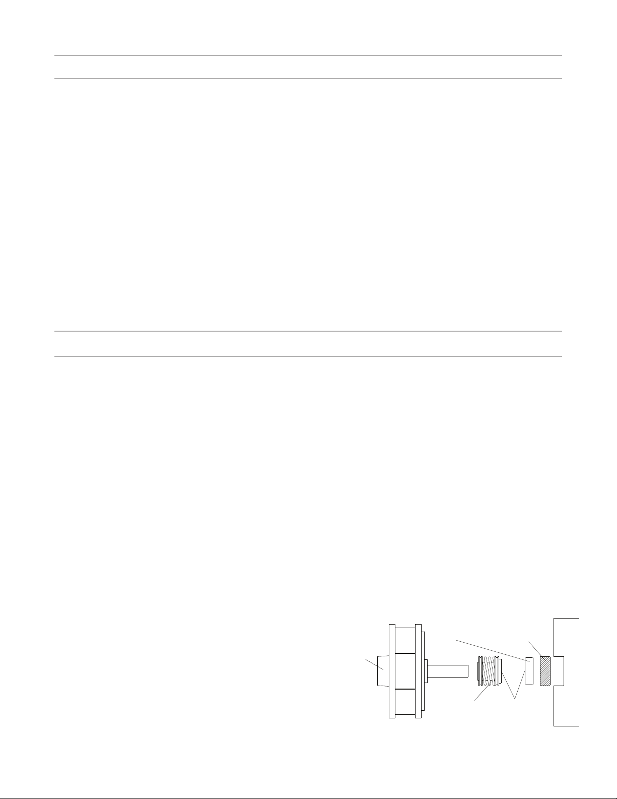
Ceramic Ring
Impeller
Shaft
Rubber Collar
8. Gently pull the mechanical seal from the impeller shaft
noting the way it was originally installed.
CAUTION: Do not damage the ceramic or carbon
surfaces of the seal. If the surfaces is damaged,
leaks will occur.
18
Spring
Assembly
Figure 3
Sealing
Surfaces
Pump Seal Housing
Page 19

Removal and Replacement of the Impeller and/or Mechanical Seal - continued
9. Using water with a small amount of dish soap, brush the impeller shaft for ease of assembly.
10. With the carbon side up, push the mechanical onto the impeller shaft and wipe carbon surface with
a clean cloth.
CAUTION: Do not use grease or lube to install seal. It will damage the seal and cause failure.
11. The ceramic side of the seal can be pushed out from the rear of the seal housing. Please note its
position before removing.
12. Using water only, wet the ceramic side of the seal and using your thumbs push into the seal housing.
Clean surface with a clean cloth.
13. Wipe the motor shaft of all debris. Re-install the seal housing and apply a single drop of Loc-tite to
the motor shaft threads.
14. Install impeller by spinning it clockwise onto the motor shaft. Continue to turn clockwise until the
carbon and ceramic sides make contact and the seal spring slightly compresses.
15. Install the diffuser by aligning the diffuser pin with the holes in the seal housing and pressing together.
16. Make sure the diffuser and casing o-rings are in place and free of debris. Slide the motor ange into
the casing.
17. Tighten the eight screws using a cross pattern from side to side and top to bottom.
CAUTION: Do not over-tighten or you will strip the casing threads.
Motor Replacement
WARNING: The pump must serviced by a professional service technician qualied in pool/spa
installation. The following procedures must be followed exactly. Improper installation and/or
operation can create dangerous electrical hazards, which can cause high voltage to run through
the electrical system. This can cause property damage, serious personal injury, and/or death.
Improper installation and/or operation will void the warranty.
1. Disconnect the wiring from the side of the motor. (Refer to the Electrical Installation on page 10)
2. Remove the eight screws holding the ange to the pump casing.
3. Slide the motor and ange from the casing.
4. Remove the diffuser by gently pulling the diffuser horizontally until the pins are clear from the seal
housing.
5. Place a at heat screwdriver through the center hole of the fan cover and into the screwdriver slot on
the motor shaft.
6. While holding the motor shaft, turn the impeller counter-clockwise.
19
Page 20
Motor Replacement - continued
7. After removal of the impeller, the seal housing will slide easily off the motor shaft.
8. Using a M8 Allen wrench, remove the four bolts and washers securing the ange to the motor.
9. Remove the slinger from the old motor and install on to the new motor.
10. Clean the surfaces of the seal (Refer to the
Removal and Replacement of the Impeller and/or
Mechanical Seal Section page 17 steps 9 -17).
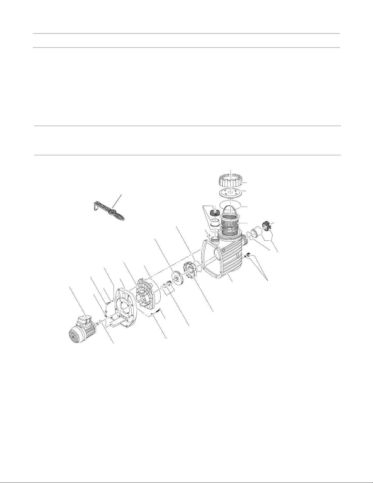
7 Product Specications
25
721
5.214
032
1.455
2.161
595
008
311
1.419
1.498
2.214
2.061
1.061
1.214
341
1.029
721.1
101
285
2.471
2.419
334
705
PART NUMBER DRAWING NUMBER QTY DESCRIPTION PART NUMBER DRAWING NUMBER QTY DESCRIPTION
2921116010 160.1 1 LID
2921116020 160.2 1 LOCK RING - LID
2901141201 412.1 1 O-RING - LID 137 x 5mm
2901114300 143 1 BASKET - ONE PIECE
2921110108 101 1 CASING
2901158200 582 1 CAP - DRAIN (3/8”) WITH GASKET - CASING
2920889410 894.1 2 LEGO SPACER
2920889420 595 1 GASKET - (1/4” x 7/16” x 1”)
2991000088 914.1 8 SCREW - CASING HEX/SLOT M7 x 48mm SS
2920141210 412.5 1 O-RING - DIFFUSER 90 x 5mm
2921117412 174.2
1 DIFFUSER
2.455
2920723101 1 IMPELLER (II) 1.0 HP S.F. 1.0 101 / 9.0mm M10
2920143310 433 1 MECHANICAL SEAL (14mm)
2921141222 412.2 1 O-RING - CASING 190 x 6mm
2921116125 161.2 1 SEAL HOUSING 14mm
2921111300 113 1 FLANGE
5879120825 914.2 4 BOLT - FLANGE M8 x 25mm
2991000062 554.2 4 WASHER - FLANGE BOLT (M8)
2500300902 721 1 SET - DISCHARGE UNION COMPLETE
2921770001 721.1 1 SET - SUCTION UNION COMPLETE
2500300914 721 & 721.1 1 COMPLETE UNION SET - SUCTION/DISCHARGE
2921157700 25 1 SPANNER - LID (OPTIONAL)
2921150700 507 1 SLINGER - SPLASH RING
230
20
Page 21
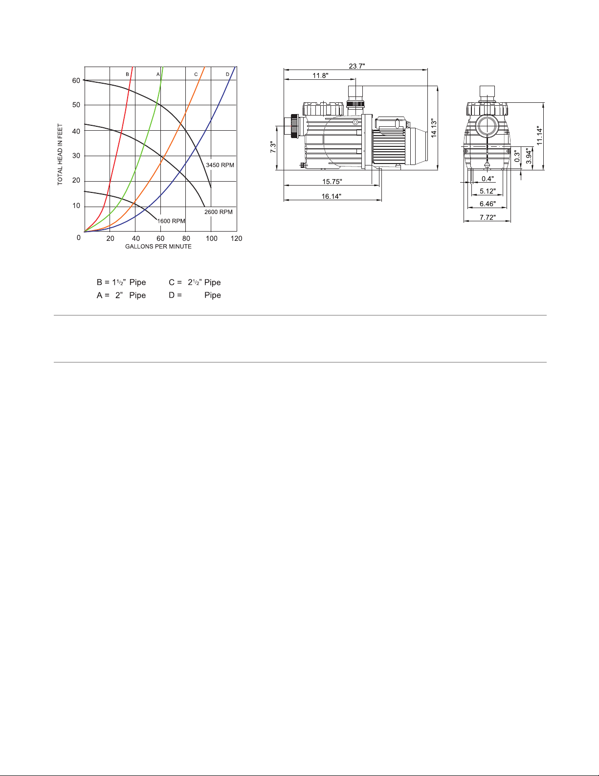
A, B, C, and D represent average system
curves for pools with below pipe diameter.
3”
8 Limited Warranty
The manufacturer supplies a limited warranty to the original consumer
purchaser of the pump and motor on the following terms and
conditions:
1. The pump and motor are warranted to be free from defects in
material and workmanship for a period of twenty-four (24) months
from the date that the pump is originally installed.
2. Not withstanding any provisions herein to the contrary, the
warranties and obligations hereunder shall not in any event extend for
more than three (3) years beyond the date of shipment of the pump
and motor from the factory in Jacksonville, Florida.
3. Warranty is void in the following cases: damages which result
in whole or in part from: (a) careless or improper installation of the
pump or the motor; (b) improper or negligent use and maintenance of
the pump or the motor; (c) tampering with the pump or the motor by
unauthorized repair personnel.
4. The manufacturer’s sole obligation hereunder shall be to replace
or repair any defective pump or motor. The manufacturer reserves
the absolute right to determine whether any defective pump or motor
should be replaced or repaired.
5. Any customer who wishes to make a claim under this Limited
Warranty shall notify the manufacturer, of such claim by telephone or
by mail. After the customer has been authorized to return a defective
pump or motor, the customer must return the pump or motor to the
manufacturer at 8125 Bayberry Road, Jacksonville, Florida 32256.
Any goods returned to manufacturer without prior authorization will be
returned to the shipper unopened.
The manufacturer shall not bear any costs or risks incurred in shipping
a defective pump or motor to the manufacturer or in shipping a repaired
or replaced pump or motor to a customer.
6. The manufacturer will charge customers for all non warranty work
which it may perform. Non-warranty work will not be performed until
the customer has accepted the price quoted.
7. EXCEPT AS SPECIFICALLY SET FORTH ABOVE, NO
OTHER WARRANTIES, WHETHER EXPRESS OR IMPLIED,
INCLUDING WITHOUT LIMITATION, THE IMPLIED WARRANTIES
OF MERCHANTABILITY AND FITNESS FOR A PARTICULAR
PURPOSE, ARE MADE BY THE MANUFACTURER. IN NO
EVENT WILL THE MANUFACTURER BE LIABLE FOR ANY LOSS,
INCLUDING TIME, MONEY, GOODWILL, LOST PROFITS AND
CONSEQUENTIAL DAMAGES BASED ON CONTRAST, TORT OR
OTHER LEGAL THEORY, WHICH MAY ARISE HEREUNDER OR
FROM THE USE, OPERATION OF MODIFICATION OF THE PUMP,
MOTOR OR ASSOCIATED PARTS. THE MAXIMUM LIABILITY OF
THE MANUFACTURER HEREUNDER SHALL NOT EXCEED THE
AMOUNT ACTUALLY PAID BY THE CUSTOMER FOR THE PUMP,
MOTOR AND ASSOCIATED PARTS.
8. Some states do not permit limitations on the terms of implied
warranties or on the recovery of incidental or consequential damages.
Accordingly, the limitations contained in paragraph 7, may not apply
to certain customers.
9. This warranty gives customers specic legal rights. Customers may
have other rights which vary from state to state.
21
Page 22

2999999995 - Rev 05/2012
 Loading...