

DE Originalbetriebsanleitung
EN Translation of original operation manual
VGX, 2VGX, MTX
WG64.022.008-P

Inhaltsverzeichnis
DE Originalbetriebsanleitung
EN Translation of original operation manual
DE Originalbetriebsanleitung
VGX, 2VGX, MTX
DE
WG64.022.008-P

SPECK Pumpen Verkaufsgesellschaft GmbH
Hauptstraße 3
91233 Neunkirchen am Sand, Germany
Telefon 09123 949-0
Telefax 09123 949-260
info@speck-pumps.com
www.speck-pumps.com
Alle Rechte vorbehalten.
Inhalte dürfen ohne schriftliche Zustimmung von
SPECK Pumpen Verkaufsgesellschaft GmbH weder
verbreitet, vervielfältigt, bearbeitet noch an Dritte
weitergegeben werden.
Dieses Dokument sowie alle Dokumente im Anhang
unterliegen keinem Änderungsdienst!
Technische Änderungen vorbehalten!
2 DE 09|2018

Inhaltsverzeichnis
Inhaltsverzeichnis
1 Zu diesem Dokument ...................................................................... 5
1.1 Umgang mit dieser Anleitung .................................................... 5
1.2 Zielgruppe ................................................................................. 5
1.2.1 Symbole und Darstellungsmittel ............................................ 5
2 Sicherheit ......................................................................................... 7
2.1 Bestimmungsgemäße Verwendung .......................................... 7
2.1.1 Mögliche Fehlanwendungen .................................................. 7
2.2 Personalqualifikation ................................................................. 7
2.3 Sicherheitsvorschriften .............................................................. 8
2.4 Schutzeinrichtungen .................................................................. 8
2.5 Bauliche Veränderungen und Ersatzteile .................................. 8
2.6 Schilder ..................................................................................... 8
2.7 Restrisiken ................................................................................ 9
2.7.1 Rotierende Teile .................................................................... 9
2.7.2 Elektrische Energie ............................................................... 9
2.7.3 Heiße Oberflächen ................................................................ 9
2.7.4 Gefahrstoffe .......................................................................... 9
2.8 Störungen ............................................................................... 10
2.9 Vermeidung von Sachschäden................................................ 10
2.9.1 Undichtigkeit und Rohrleitungsbruch ................................... 10
2.9.2 Trockenlauf ......................................................................... 10
2.9.3 Kavitation ............................................................................ 10
2.9.4 Überhitzen ........................................................................... 11
2.9.5 Druckstöße .......................................................................... 11
2.9.6 Blockieren der Pumpe ......................................................... 11
2.9.7 Leckageabfluss ................................................................... 11
2.9.8 Frostgefahr .......................................................................... 11
2.9.9 Sichere Nutzung des Produktes .......................................... 11
3 Beschreibung ................................................................................. 12
3.1 Ausführung VGX/2VGX ........................................................... 12
3.2 Ausführung MTX ..................................................................... 12
3.3 Werkstoffe ............................................................................... 12
3.4 Konstruktion ............................................................................ 12
4 Transport und Zwischenlagerung ................................................ 13
09|2018 DE 3

Inhaltsverzeichnis
4.1 Transport ................................................................................. 13
4.2 Lagerung ................................................................................. 13
4.3 Rücksendung .......................................................................... 13
5 Installation ...................................................................................... 14
5.1 Einbau ..................................................................................... 14
5.1.1 Aufstellen ............................................................................ 14
5.1.2 Bodenablauf muss vorhanden sein ..................................... 14
5.1.3 Be- und Entlüftung ............................................................... 14
5.2 Rohrleitungen .......................................................................... 14
5.2.1 Rohrleitungen dimensionieren ............................................. 14
5.2.2 Rohrleitungen verlegen ....................................................... 14
5.3 Aufstellung .............................................................................. 15
5.3.1 Pumpe aufstellen und an die Rohrleitung anschließen ........ 15
5.4 Elektrischer Anschluss ............................................................ 16
5.4.1 Anschlussplan ..................................................................... 17
6 Inbetriebnahme/Außerbetriebnahme ........................................... 18
6.1 Inbetriebnahme ....................................................................... 18
6.1.1 Pumpe auf Leichtgängigkeit prüfen ..................................... 18
6.1.2 Pumpe einschalten .............................................................. 18
6.2 Außerbetriebnahme................................................................. 19
7 Störungen ....................................................................................... 20
7.1 Übersicht ................................................................................. 20
8 Wartung/Instandhaltung ................................................................ 23
8.1 Gewährleistung ....................................................................... 23
8.2 Serviceadressen ..................................................................... 23
9 Entsorgung .................................................................................... 24
10 Technische Daten ...................................................................... 25
10.1 Maßzeichnung ......................................................................... 28
10.2 Kennlinie ................................................................................. 34
10.3 Explosionszeichnung ............................................................... 44
11 Index ............................................................................................ 49
4 DE 09|2018
g
1 Zu diesem Dokument
1.1 Umgang mit dieser Anleitung
Diese Anleitung ist Teil der Pumpe/Anlage. Die Pumpe/Anlage
wurde nach den anerkannten Regeln der Technik hergestellt und
geprüft. Dennoch können bei unsachgemäßer Verwendung, bei
unzureichender Wartung oder unzulässigen Eingriffen Gefahren
für Leib und Leben sowie materielle Schäden entstehen.
Anleitung vor Gebrauch aufmerksam lesen.
Anleitung während der Lebensdauer des Produktes
aufbewahren.
Anleitung dem Bedien- und Wartungspersonal jederzeit
zugänglich machen.
Anleitung an jeden nachfolgenden Besitzer oder Benutzer
des Produktes weitergeben.
Zu diesem Dokument
1.2 Zielgruppe
Diese Betriebsanleitung richtet sich an qualifiziertes
1.2.1 Symbole und Darstellungsmittel
Fachpersonal.
In dieser Anleitung werden Warnhinweise verwendet, um Sie vor
Personenschäden zu warnen.
Warnhinweise immer lesen und beachten.
GEFAHR
Gefahren für Personen.
Nichtbeachtun
führt zu Tod oder schweren Verletzungen.
WARNUNG
Gefahren für Personen.
Nichtbeachtung kann zu Tod oder schweren Verletzungen führen.
VORSICHT
Gefahren für Personen.
Nichtbeachtung kann zu leichten bis mäßigen Verletzungen
führen.
09|2018 DE 5

Zu diesem Dokument
HINWEIS
Hinweise zur Vermeidung von Sachschäden, zum Verständnis
oder zum Optimieren der Arbeitsabläufe.
Um die korrekte Bedienung zu verdeutlichen, sind wichtige
Informationen und technische Hinweise besonders
hervorgehoben.
Symbol Bedeutung
1.
2.
Einschrittige Handlungsaufforderung.
Mehrschrittige Handlungsaufforderung.
Reihenfolge der Schritte beachten.
6 DE 09|2018

2 Sicherheit
2.1 Bestimmungsgemäße Verwendung
Die Pumpe ist geeignet für Wasseraufbereitung, Wasserversorgung, Kühlanlagen, Apparatebau und Druckerhöhung. Gefördert
werden sollte sauberes Wasser und Medien, welche die
Werkstoffe nicht angreifen.
Zur bestimmungsgemäßen Verwendung gehört die Beachtung
folgender Informationen:
Sicherheit
Die Pumpe/Anlage darf nur innerhalb der Einsatzgrenzen und
Kennlinien betrieben werden, die in dieser Anleitung festgelegt
• Diese Anleitung
sind.
Eine andere oder darüber hinausgehende Verwendung ist nicht
bestimmungsgemäß und muss zuvor mit dem
Hersteller/Lieferanten abgesprochen werden.
2.1.1 Mögliche Fehlanwendungen
• Einbau der Pumpe/Anlage bei verspanntem Zustand des
Rohrsystems.
• Betrieb der Pumpe/Anlage außerhalb des Einsatzbereichs,
der im Pumpendatenblatt spezifiziert ist, zum Beispiel bei zu
hohem Systemdruck.
• Öffnen und Instandhalten der Pumpe/Anlage durch nicht
qualifiziertes Personal.
2.2 Personalqualifikation
Dieses Gerät kann von Kindern ab 8 Jahren und darüber sowie
von Personen mit verringerten physischen, sensorischen oder
mentalen Fähigkeiten oder Mangel an Erfahrung und Wissen
benutzt werden, wenn sie beaufsichtigt oder bezüglich des
sicheren Gebrauchs des Gerätes unterwiesen wurden und die
daraus resultierenden Gefahren verstehen. Kinder dürfen nicht
mit dem Gerät spielen. Reinigung und Benutzerwartung dürfen
nicht von Kindern ohne Beaufsichtigung durchgeführt werden.
Sicherstellen, dass folgende Arbeiten nur von geschultem
Fachpersonal mit den genannten Personalqualifikationen
durchgeführt werden:
– Arbeiten an der Mechanik, zum Beispiel Wechsel der
Kugellager oder der Gleitringdichtung: qualifizierter
Mechaniker.
09|2018 DE 7

Sicherheit
– Arbeiten an der elektrischen Anlage: Elektrofachkraft.
Sicherstellen, dass folgende Voraussetzungen erfüllt sind:
– Das Personal, das die entsprechende Qualifikation noch
nicht aufweisen kann, erhält die erforderliche Schulung,
bevor es mit anlagentypischen Aufgaben betraut wird.
– Die Zuständigkeiten des Personals, zum Beispiel für
Arbeiten am Produkt, an der elektrischen Ausrüstung oder
den hydraulischen Einrichtungen, sind entsprechend
seiner Qualifikation und Arbeitsplatzbeschreibung
festgelegt.
– Das Personal hat diese Anleitung gelesen und die
erforderlichen Arbeitsschritte verstanden.
2.3 Sicherheitsvorschriften
Für die Einhaltung aller relevanten gesetzlichen Vorschriften und
Richtlinien ist der Betreiber der Anlage verantwortlich.
Bei Verwendung der Pumpe/Anlage folgende Vorschriften
beachten:
– Diese Anleitung
– Warn- und Hinweisschilder am Produkt
– Die bestehenden nationalen Vorschriften zur
Unfallverhütung
– Interne Arbeits-, Betriebs- und Sicherheitsvorschriften des
Betreibers
2.4 Schutzeinrichtungen
Das Hineingreifen in bewegliche Teile, zum Beispiel Lüfterrad,
kann schwere Verletzungen verursachen.
Pumpe/Anlage nur mit Berührungsschutz betreiben.
2.5 Bauliche Veränderungen und Ersatzteile
Umbau oder Veränderungen können die Betriebssicherheit
beeinträchtigen.
Pumpe/Anlage nur in Absprache mit dem Hersteller
umbauen oder verändern.
Nur Originalersatzteile oder -zubehör verwenden, das vom
Hersteller autorisiert ist.
2.6 Schilder
Alle Schilder auf der gesamten Pumpe/Anlage in lesbarem
Zustand halten.
8 DE 09|2018

2.7 Restrisiken
2.7.1 Rotierende Teile
Scher- und Quetschgefahr besteht aufgrund von offenliegenden
rotierenden Teilen.
Alle Arbeiten nur bei Stillstand der Pumpe/Anlage
durchführen.
Vor Arbeiten die Pumpe/Anlage gegen Wiedereinschalten
sichern.
Unmittelbar nach Abschluss der Arbeiten alle
Schutzeinrichtungen wieder anbringen beziehungsweise in
Funktion setzen.
2.7.2 Elektrische Energie
Eine nicht ordnungsgemäß durchgeführte Installation der
elektrischen Schutzleiter kann zum Stromschlag führen, zum
Beispiel durch Oxidation oder Kabelbruch.
Sicherheit
VDE- und EVU-Vorschriften des
Energieversorgungsunternehmens beachten.
Vor Arbeiten an der elektrischen Anlage folgende
Maßnahmen ergreifen:
– Anlage von der Spannungsversorgung trennen.
– Warnschild anbringen: „Nicht einschalten! An der Anlage
wird gearbeitet."
– Spannungsfreiheit prüfen.
Elektrische Anlage regelmäßig auf ordnungsgemäßen
Zustand prüfen.
2.7.3 Heiße Oberflächen
Die Pumpe kann während des Betriebes sehr heiß werden.
Dadurch besteht Verbrennungsgefahr.
Pumpe im Betrieb nicht berühren.
Vor Arbeiten an der Pumpe/Anlage die Pumpe erst abkühlen
lassen.
2.7.4 Gefahrstoffe
Sicherstellen, dass Leckagen gefährlicher Fördermedien
ohne Gefährdung von Personen und Umwelt abgeführt
werden.
Pumpe bei der Demontage vollständig dekontaminieren.
09|2018 DE 9

Sicherheit
2.8 Störungen
Bei Störungen Anlage sofort stilllegen und ausschalten.
Alle Störungen umgehend beseitigen lassen.
Festsitzende Pumpe
Wird eine festsitzende Pumpe mehrmals hintereinander
eingeschaltet, kann der Motor beschädigt werden. Folgende
Punkte beachten:
Pumpe/Anlage nicht mehrmals hintereinander einschalten.
Motorwelle von Hand durchdrehen. .
Pumpe reinigen.
2.9 Vermeidung von Sachschäden
2.9.1 Undichtigkeit und Rohrleitungsbruch
Durch Überschreitung der Rohrleitungskräfte können undichte
Stellen an den Flanschverbindungen oder an der Pumpe selbst
entstehen.
Pumpe nicht als Festpunkt für die Rohrleitung verwenden.
Rohrleitungen spannungsfrei anschließen und elastisch
lagern. Gegebenenfalls Kompensatoren einbauen.
Bei Undichtigkeit der Pumpe darf die Anlage nicht betrieben
werden und muss vom Netz genommen werden.
2.9.2 Trockenlauf
Durch Trockenlauf können verschiedene Bauteile innerhalb
weniger Sekunden zerstört werden.
Pumpe nicht trocken laufen lassen.
Pumpe vor dem Anfahren entlüften.
2.9.3 Kavitation
Zu lange Rohrleitungen erhöhen den Widerstand. Dadurch
besteht Gefahr der Kavitation.
Sicherstellen, dass die Saugleitung dicht ist.
Maximale Leitungslänge beachten.
Saugseitige Armatur vollständig öffnen.
10 DE 09|2018

2.9.4 Überhitzen
Folgende Faktoren können zu einer Überhitzung der Pumpe
führen:
• ungenügende Kühlung der Pumpe.
• geschlossener Schieber in der Druckleitung.
Pumpe nicht trocken laufen lassen.
Sicherheit
Pumpe nicht bei geschlossenen Armaturen betreiben.
2.9.5 Druckstöße
Schlagartig schließende Armaturen können Druckstöße
verursachen, die den maximal zulässigen Gehäusedruck der
Pumpe mehrfach übersteigen.
Schlagartig schließende Armaturen vermeiden,
beziehungsweise, wenn vorhanden, langsam schließen.
2.9.6 Blockieren der Pumpe
Schmutzteilchen können die Pumpe verstopfen und blockieren.
Pumpe vor Inbetriebnahme und längerer Stillstands- oder
Lagerzeit auf Leichtgängigkeit prüfen.
2.9.7 Leckageabfluss
Unzureichender Leckageabfluss kann den Motor beschädigen.
Leckageabfluss zwischen Pumpengehäuse und Motor nicht
verstopfen oder abdichten.
2.9.8 Frostgefahr
Pumpe/Anlage und frostgefährdete Leitungen rechtzeitig
entleeren.
Pumpe/Anlage während der Frostperiode ausbauen und in
einem trockenen Raum lagern.
2.9.9 Sichere Nutzung des Produktes
Eine sichere Nutzung des Produktes ist bei folgenden Punkten
nicht mehr gewährleistet:
Bei nicht ordnungsgemäßem Zustand des
Rohrleitungssystems.
Bei festsitzender Pumpe. .
Bei schadhafter oder fehlender Schutzeinrichtungen, zum
Beispiel Berührungsschutz.
Wenn die Pumpe/Anlage bei verspanntem Zustand des
Rohrsystems eingebaut wird.
09|2018 DE 11
Beschreibung
A
A
A
A
g
3 Beschreibung
3.1 Ausführung VGX/2VGX
Die Pumpen der Baureihe VGX/2VGX sind Blockpumpen mit
oberflächengekühltem Motor, verlängerter Motorwelle zur
Aufnahme der Laufräder, Wellendichtung durch Gleitringdichtung,
ausgelegt für Dauerbetrieb.
3.2 Ausführung MTX
Die Pumpen der Baureihe MTX sind mehrstufige, horizontale
Kreiselpumpen mit oberflächengekühltem Motor, verlängerter
Motorwelle zur Aufnahme der Laufräder, Wellendichtung durch
Gleitringdichtung ausgelegt für Dauerbetrieb.
3.3 Werkstoffe
VGX
Gehäuse Edelstahl 1.4301
Laufrad Edelstahl 1.4301
Welle Edelstahl 1.4305
Motorträger
luminium
Gleitringdichtung Kohle/Keramik*
O-Ringe NBR*
Motorgehäuse
luminium
* andere Varianten auf Anfrage
MTX
Gehäuse Edelstahl 1.4301
Laufrad Edelstahl 1.4301
Welle Edelstahl 1.4301
Dichtungsträger Edelstahl 1.4301
Motorträger
luminium
Gleitringdichtung Kohle/Keramik*
O-Ringe EPDM*
Motorgehäuse
luminium
* andere Varianten auf Anfrage
3.4 Konstruktion
Laufrad
Wellendichtung Gleitringdichtung
Lagerung abgedichtete Rillenkugellager
12 DE 09|2018
eschlossen

Transport und Zwischenlagerung
4 Transport und Zwischenlagerung
4.1 Transport
Lieferzustand kontrollieren.
– Verpackung auf Transportschäden prüfen.
– Schaden feststellen, mit Bildern dokumentieren und an
den Händler wenden.
4.2 Lagerung
HINWEIS
Korrosion durch Lagerung in feuchter Luft bei wechselnden
Temperaturen!
Kondenswasser kann Wicklungen und Metallteile angreifen.
Pumpe/Anlage in trockener Umgebung bei möglichst
konstanter Temperatur zwischenlagern.
HINWEIS
Beschädigung der Öffnung und Eindringen von Fremdkörpern
durch ungeschützte Stutzen!
Stutzenabdeckung erst vor Anschließen der Rohrleitungen
entfernen.
HINWEIS
Beschädigung oder Verlust von Einzelteilen!
Originalverpackung erst vor dem Einbau öffnen
beziehungsweise Einzelteile bis zum Einbau in der
Originalverpackung aufbewahren.
4.3 Rücksendung
– Pumpe/Anlage vollständig entleeren.
– Pumpe/Anlage mit klarem Wasser spülen und reinigen.
– Pumpe/Anlage in Karton verpacken und an den Fachbetrieb
beziehungsweise Hersteller senden.
09|2018 DE 13

Installation
5 Installation
5.1 Einbau
5.1.1 Aufstellen
Die Pumpe muss trocken und horizontal aufgestellt werden.
5.1.2 Bodenablauf muss vorhanden sein
Größe des Bodenablaufs nach folgenden Kriterien
bemessen:
– Maximaler Volumenstrom der Pumpe.
5.1.3 Be- und Entlüftung
Für ausreichende Be- und Entlüftung sorgen. Be- und
Entlüftung müssen folgende Bedingungen sicherstellen:
– Vermeidung von Kondenswasser.
– Kühlung des Pumpenmotors und anderer Anlagenteile,
zum Beispiel der Schaltschränke und Steuergeräte.
– Begrenzung der Umgebungstemperatur auf maximal
40 °C.
5.2 Rohrleitungen
5.2.1 Rohrleitungen dimensionieren
Leitung mit Gewindeanschluss ist entsprechend dem Druck-
beziehungsweise Saugstutzen oder größer vorzusehen.
Bei fester Installation, Leitungen aus Metall oder Kunststoff
verwenden.
Bei zeitweiliger Installation können Kunststoffschläuche
verwendet werden. Diese müssen dem Druck
beziehungsweise Vakuum der Pumpe standhalten.
5.2.2 Rohrleitungen verlegen
Druckleitung möglichst gerade halten.
Plötzliche Querschnitts- und Richtungsänderungen
vermeiden.
Rückschlagventil an Druckleitung montieren.
Pumpe nicht als Festpunkt für die Rohrleitung verwenden.
Vor der Montage die Bauteile reinigen und spannungsfrei mit
geeignetem Dichtungsmaterial an die Pumpe anschließen.
14 DE 09|2018

Installation
g
5.3 Aufstellung
5.3.1 Pumpe aufstellen und an die Rohrleitung anschließen
1. Pumpe horizontal und trocken aufstellen.
HINWEIS
Beschädigung des Motors durch unzureichenden Leckageabfluss!
Leckageabfluss zwischen Pumpengehäuse und Motor nicht
verstopfen oder abdichten.
HINWEIS
Durch unsachgemäße Abdichtung können Gewinde beschädigt
und die Dichtwirkun
beeinträchtigt werden!
HINWEIS
Beschädigung der Pumpe durch unzulässige mechanische
Spannungen!
Rohrleitungen unmittelbar vor der Pumpe abstützen und
spannungsfrei anschließen.
2. Rohrleitungen spannungsfrei gemäß VDMA-Einheitsblatt
24277 anschließen. Gegebenenfalls Kompensatoren
verwenden.
3. Sicherstellen, dass eventuelle Leckagen keine Folgeschäden
verursachen können. Gegebenenfalls eine entsprechende
Auffangvorrichtung einbauen.
WARNUNG
Gesundheitsgefährdende Fördermedien!
Gesetzliche Bestimmungen bezüglich der Entsorgung von
gesundheitsgefährdenden Medien beachten.
09|2018 DE 15
Installation
5.4 Elektrischer Anschluss
WARNUNG
Stromschlaggefahr durch unsachgemäßen Anschluss!
Elektrische Anschlüsse und Verbindungen müssen immer
von autorisiertem Fachpersonal vorgenommen werden.
VDE- und EVU-Vorschriften des
Energieversorgungsunternehmens beachten.
Trennvorrichtung zur Unterbrechung der
Spannungsversorgung mit einer Kontaktöffnung von
Stromkreis mit einer Fehlerstromschutzeinrichtung,
mindestens 3 mm pro Pol installieren.
Nennfehlerstrom I
≤ 30 mA, schützen.
FN
Nur geeignete Leitungstypen entsprechend den regionalen
Vorschriften verwenden.
Mindestquerschnitt der elektrischen Leitungen der
Motorleistung und der Leitungslänge anpassen.
Leitungen nicht knicken oder quetschen.
Wenn sich gefährliche Situationen ergeben können, Not-Aus-
Schalter gemäß DIN EN 809 vorsehen. Entsprechend dieser
Norm muss das der Errichter/Betreiber entscheiden.
WARNUNG
Stromschlaggefahr durch Spannung am Gehäuse!
Bei Pumpen mit Drehstrommotor, muss ein korrekt
eingestellter Motorschutzschalter installiert werden. Dabei die
Werte auf dem Typenschild beachten.
HINWEIS
Beim Anschluss ist darauf zu achten, dass die Pumpe erst nach
dem Füllen des Systems in Betrieb genommen wird, da die
Pumpe sonst trocken laufen kann und Schaden nimmt.
Der Wechselstrommotor verfügt über einen thermischen
Überlastschutz. Dieser schaltet bei Überlastung der Pumpe
automatisch ab und nach Abkühlung wieder ein.
16 DE 09|2018
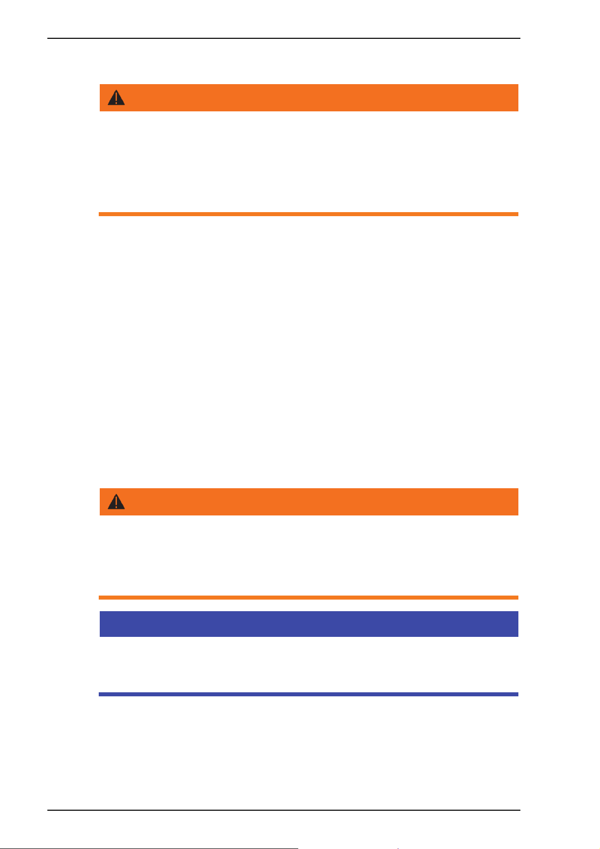
5.4.1 Anschlussplan
COMMON
M
MAIN
AUX
1~
W2
Installation
P
PE
U2
V1
U1
C
L1
N
V2
V1
U1
W1
WG27.50.095-P
M
3~
V2
U2
W2
U2
W2
W1
V1
U1
Drehstrommotoren 230/400 V werden bei 230 V im Dreieck und
bei 400 V im Stern angeschlossen.
PE
L1
L2
L3
V1
U1
W1
M
3~
V2
U2
W2
V2
U2
W2
W1
V1
U1
PE
L1
L2
L3
09|2018 DE 17

Inbetriebnahme/Außerbetriebnahme
g
6 Inbetriebnahme/Außerbetriebnahme
6.1 Inbetriebnahme
HINWEIS
Beschädigung der Pumpe/Anlage durch Trockenlauf!
Sicherstellen, dass die Pumpe/Anlage immer mit Wasser
gefüllt ist. Dies gilt auch bei der Drehrichtungskontrolle.
6.1.1 Pumpe auf Leichtgängigkeit prüfen
Nach längerer Stillstandszeit muss die Pumpe im ausgeschalteten
und spannungsfreien Zustand auf Leichtgängigkeit geprüft
werden.
Schraubendreher in den Schlitz am Motorwellenende, auf der
Lüfterseite, stecken und durchdrehen.
– Oder –
Wenn kein Schlitz am Motorwellenende vorhanden ist:
Lüfterhaube entfernen und Lüfterrad manuell in
Motordrehrichtung drehen.
6.1.2 Pumpe einschalten
1. Armaturen ganz öffnen.
HINWEIS
Beschädigung der Pumpe durch Trockenlauf!
Pumpe und Saugleitung entlüften.
2. Pumpe/Anlage einschalten.
HINWEIS
Wenn die Pumpe einen Drehstrommotor hat und dieser sich in die
falsche Richtung dreht, ist die Pumpe/Anlage lauter und fördert
weni
er.
3. Bei Drehstrommotor: Darauf achten, dass sich der Motor in
Richtung des aufgeklebten Drehrichtungspfeils auf der
Lüfterhaube dreht. Bei falscher Drehrichtung eine
Elektrofachkraft benachrichtigen.
4. Dichtigkeit der Gleitringdichtung prüfen.
18 DE 09|2018

Inbetriebnahme/Außerbetriebnahme
6.2 Außerbetriebnahme
1. Pumpe ausschalten.
2. Saug- und druckseitige Armatur schließen.
3. Pumpe und Leitungen entleeren.
4. Bei Frostgefahr Pumpe und frostgefährdete Leitungen an
einem trockenen und frostsicheren Ort lagern.
09|2018 DE 19
Störungen
7 Störungen
HINWEIS
Es ist normal, dass von Zeit zu Zeit einige Tropfen Wasser durch
die Gleitringdichtung austreten. Das gilt insbesondere während
der Einlaufzeit.
Je nach Wasserbeschaffenheit und Betriebsstundenzahl kann die
Gleitringdichtung undicht werden.
Bei permanentem Wasseraustritt Gleitringdichtung von einem
Fachmann wechseln lassen.
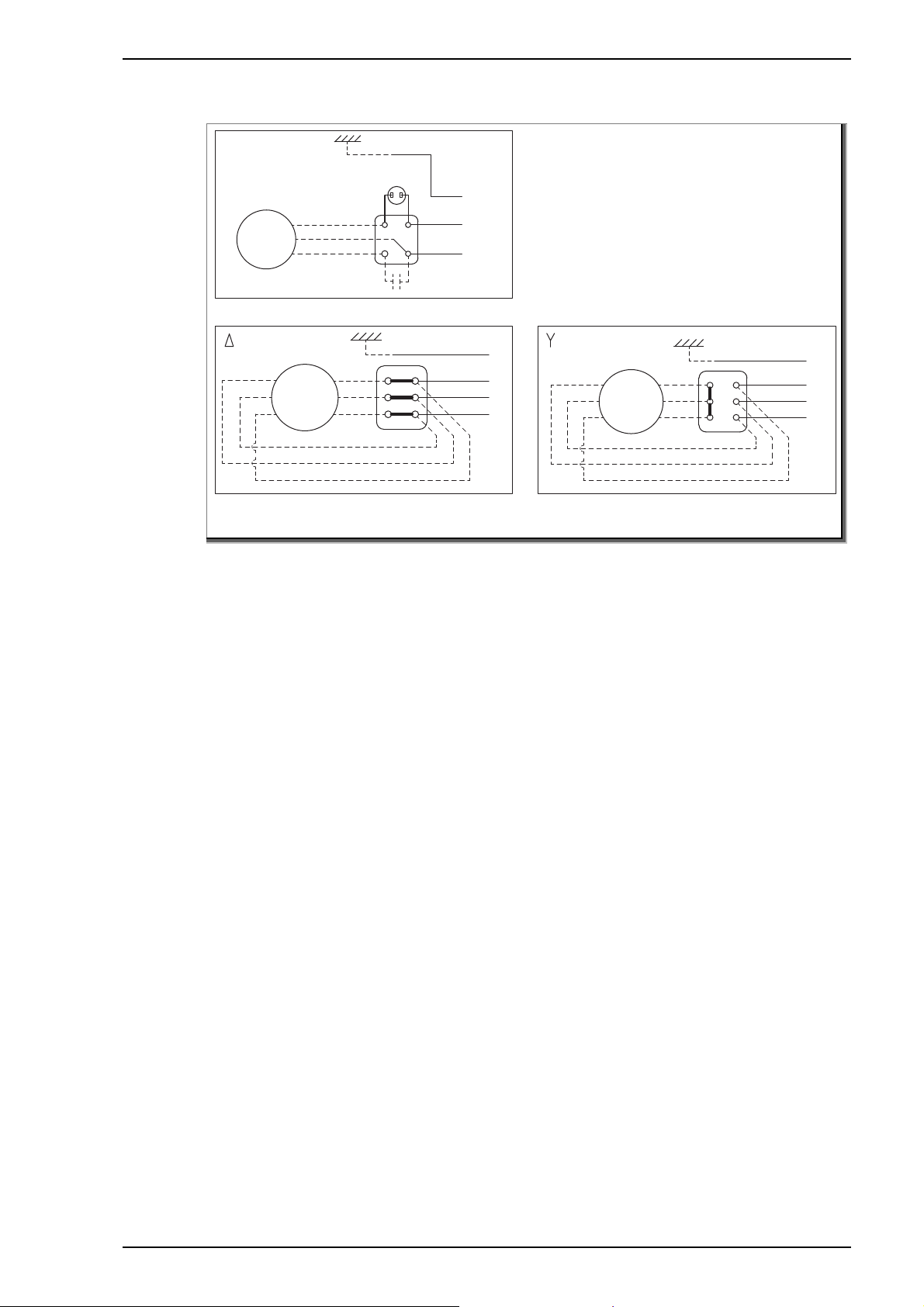
7.1 Übersicht
Störung: Motor läuft nicht an
Mögliche Ursache Abhilfe
Motorschutz hat ausgelöst.
Abwarten, bis Motorwicklung
abgekühlt ist und
Motorschutz wieder
einschaltet (1~).
Motorschutzschalter prüfen
(3~).
Es liegt keine Spannung an. Stromversorgung prüfen.
Sicherung durchgebrannt. Sicherung auswechseln; bei
erneutem Durchbrennen,
elektrischen Anschluss
prüfen.
Motor oder Kondensator
defekt.
Motor/Kondensator
austauschen.
Störung: Kein Förderstrom; Motor dreht
Mögliche Ursache Abhilfe
Absperrventil geschlossen. Absperrventil öffnen.
Pumpe nicht mit Medium
Pumpe befüllen.
befüllt.
Leckage in der
Anlage/Leitung.
Rohrleitungen prüfen und
reparieren.
20 DE 09|2018
Störungen
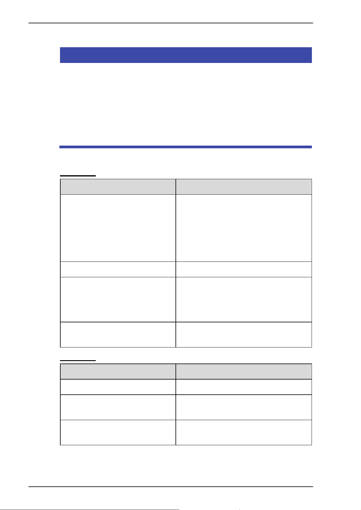
Störung: Zu geringer Förderstrom der Pumpe
Mögliche Ursache Abhilfe
Falsche Drehrichtung (3).
Elektrische Anschlüsse
anhand der Anleitung prüfen.
Pumpe oder Leitung
Prüfen und Reinigen.
verunreinigt oder teilweise
blockiert.
Störung: Pumpe schaltet ständig aus
Mögliche Ursache Abhilfe
Motorschutz hat ausgelöst. Pumpe auf Verunreinigung
prüfen.
Pumpe/Pumpenteile
reinigen.
Fördermedium ist zu viskos.
Pumpe läuft außerhalb der
Kennlinie.
Arbeitspunkt der Pumpe
korrigieren.
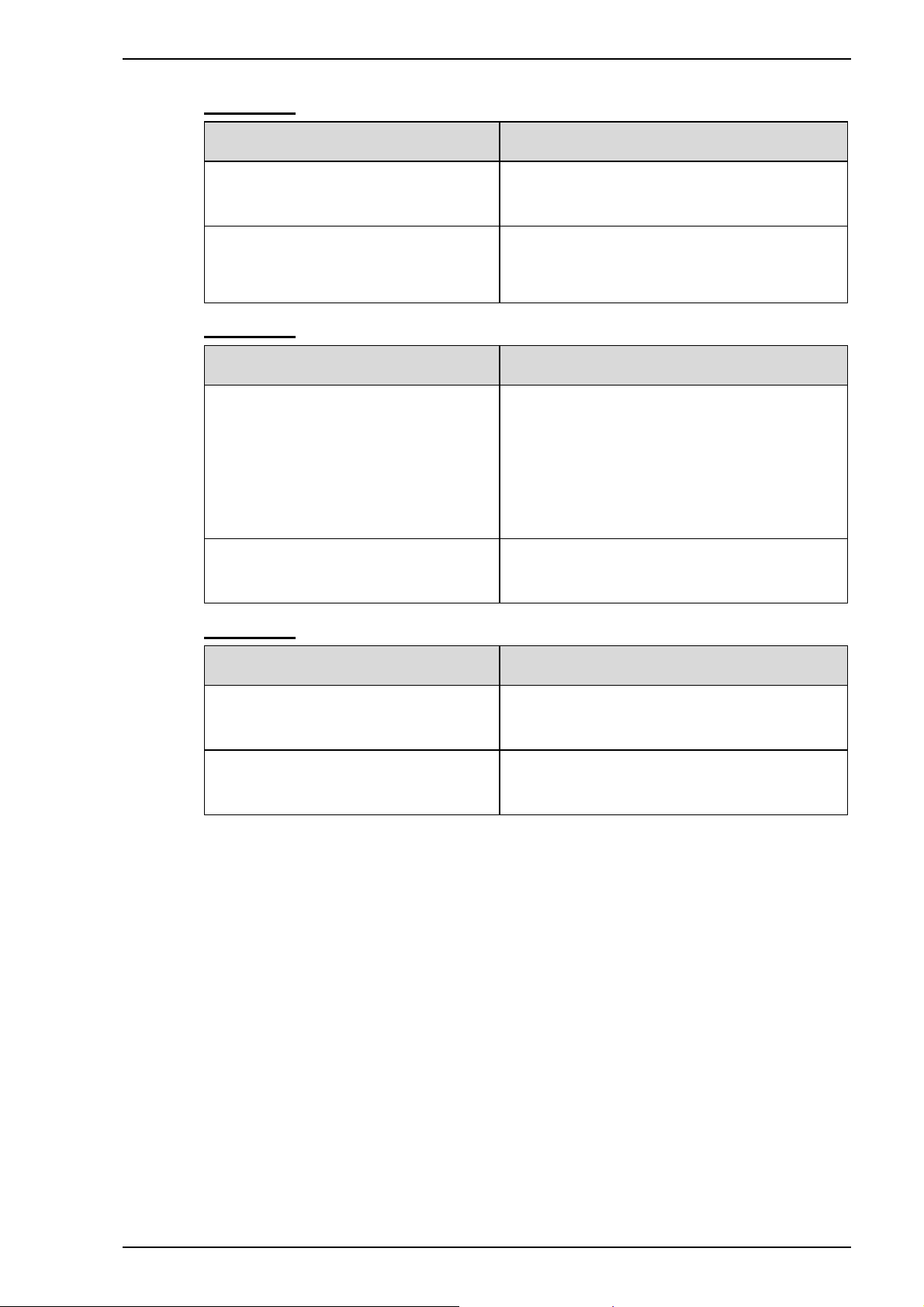
Störung: Leckage zwischen Pumpe und Motor
Mögliche Ursache Abhilfe
Wellendichtung verschlissen
oder beschädigt.
Trockenlauf der Pumpe. Wellendichtung
Wellendichtung
austauschen.
austauschen.
09|2018 DE 21

Störungen
Störung: Pumpe vibriert und/oder verursacht Geräusche
Mögliche Ursache Abhilfe
Pumpe nicht mit Medium
befüllt.
Kein oder unzureichender
Zulauf.
Lager der Pumpe und/oder
des Motors sind schadhaft.
Vorhandener NPSH-Wert zu
niedrig (Kavitation).
Pumpe arbeitet nicht in
ihrem Betriebsbereich.
Pumpe befüllen und
entlüften.
Ausreichende Medium-
Versorgung sicherstellen.
Rohrleitungen prüfen und
reparieren.
Lager austauschen.
Saugbedingungen
verbessern.
System für den Betrieb
innerhalb des
Betriebsbereichs anpassen
oder eine passende Pumpe
auswählen.
Pumpe steht auf einer
unebenen Oberfläche.
Oberfläche ebnen oder die
Pumpe fest mit dem
Untergrund verbinden.
22 DE 09|2018
8 Wartung/Instandhaltung
HINWEIS
Vor Instandhaltungsarbeiten alle Absperrarmaturen schließen
und Leitungen entleeren.
Wann? Was?
Regelmäßig Laufgeräusche überprüfen.
Pumpe auf Undichtigkeit prüfen.
Bei Frostgefahr Pumpe und frostgefährdete
Leitungen rechtzeitig entleeren.
Nach Beendigung der Instandhaltungsarbeiten alle
erforderlichen Maßnahmen für die Inbetriebnahme ergreifen.
Wartung/Instandhaltung
8.1 Gewährleistung
Die Gewährleistung erstreckt sich auf die gelieferten Geräte mit
allen Teilen. Ausgenommen sind jedoch natürliche
Abnutzung/Verschleiß (DIN 3151/DIN-EN 13306) aller drehenden
beziehungsweise dynamisch beanspruchter Bauteile,
einschließlich spannungsbelasteter Elektronik-Komponenten.
Die Nichtbeachtung der Sicherheitshinweise kann zum Verlust
jeglicher Schadensersatzansprüche führen.
8.2 Serviceadressen
Serviceadressen und Adressen von Kundendiensten sind auf der
Internetseite www.speck-pumps.com zu finden.
09|2018 DE 23

Entsorgung
9 Entsorgung
Schädliche Fördermedien auffangen und vorschriftsgemäß
entsorgen.
Die Pumpe/Anlage beziehungsweise die Einzelteile müssen
nach Lebensdauerende fachgerecht entsorgt werden. Eine
Entsorgung im Hausmüll ist nicht zulässig!
Verpackungsmaterial, unter Beachtung der örtlichen
Vorschriften, im Hausmüll entsorgen.
24 DE 09|2018
10 Technische Daten
VGX 50 Hz
Technische Daten
Konden-
Stromauf-
Typ P2
nahme
sator
[A]
VGX [kW] [µF] [VDB]
7/5
7/7
9/10
12/7
12/12
12/20
20/12
20/20
20/25
0,37 12,5 450 3,40 1,40 90 9,10/9,10 55
0,55 16 450 5,00 2,00 90 10,4/10,4 55
0,75 20 450 5,60 1,70 90 11,9/11,9 55
0,55 16 450 4,60 1,85 90 10,4/10,4 55
0,90 31,5 450 6,90 3,50 90 12,5/12,5 55
1,50 40 450 9,30 4,10 90 17,2/17,2 55
0,90 31,5 450 6,30 2,50 90 16,3/16,3 55
1,50 40 450 10,2 4,10 90 15,3/15,3 55
1,80 - 450 - 4,70 90 -/17,0 55
1~
230 V
3~
400 V
Max.
Medien-
Gewicht
1~/3~
Schutz-
art
temperatur
[°C] [kg] IP
VGX 60 Hz
Max.
Medien-
temperatur
Gewicht
1~/3~
Schutz-
art
Typ P2
Konden-
Stromauf-
nahme
sator
[A]
VGX [kW] [µF] [VDB]
7/7
7/10
7/15
12/10
12/15
12/20
20/15
20/20
20/30
0,55 1,5 450 7,50 1,20 90 8,50/8,00 55
075 14 450 9,40 1,70 90 9,50/10,0 55
1,10 25 450 - 2,20 90 11,7/13,0 55
0,75 14 450 10,4 1,70 90 9,50/10,0 55
1,10 25 450 - 2,20 90 11,7/12,0 55
1,50 35 450 - 4,70 90 15,3/15,0 55
1,10 20 450 - 1,70 90 11,0/11,0 55
1,50 35 450 - 4,70 90 15,0/16,0 55
2,20 - - - 4,70 90 -/17,0 55
230 V
1~
3~
400 V
[°C] [kg] IP
09|2018 DE 25
Technische Daten
2VGX 50 Hz
Stromauf-
Max.
Gewicht
Schutz-
Konden-
Typ P2
nahme [A]
Medien-
1~/3~
art
sator
temperatur
2VGX [kW] [µF] [VDB]
7/10
7/12
7/15
7/20
12/15
12/20
12/30
12/40
20/30
20/40
20/50
0,75 20 450 6,00 1,70 90 12,6/12,6 55
0,90 31,5 450 7,00 2,50 90 13,7/13,7 55
1,10 40 450 8,10 3,30 90 17,0/17,0 55
1,50 40 450 10,0 4,10 90 19,2/20,1 55
1,10 40 450 8,30 3,30 90 15,6/15,6 55
1,50 40 450 10,2 4,10 90 17,4/18,3 55
2,20 - - - 4,70 90 -/26,1 55
3,00 - - - 6,40 90 -/27,8 55
2,20 - - - 6,40 90 -/26,6 55
3,00 - - - 6,40 90 -/27,6 55
3,70 - - - 8,70 90 -/35,6 55
1~
230 V
3~
400 V
[°C] [kg] IP
2VGX 60 Hz
Konden-
Typ P2
sator
2VGX [kW] [µF] [VDB]
7/10
7/20
7/30
12/20
12/30
12/40
20/40 R
20/40
20/50
0,75 20 450 6,40 1,70 90 12,6/12,0 55
1,50 35 450 9,90 4,70 90 16,6/16,0 55
2,20 35 450 11,9 4,70 90 16,916,0 55
1,50 - - - 4,70 90 -/17,5 55
2,20 - - - 4,70 90 -/20,1 55
3,00 - - - 6,10 90 -/25,9 55
3,00 - - - 6,10 90 -/25,7 55
3,00 - - - 6,10 90 -/25,7 55
4,00 - - - 9,00 90 -/35,7 55
Stromauf-
nahme [A]
1~
230 V
3~
400 V
Max.
Medien-
Gewicht
1~/3~
Schutz-
art
temperatur
[°C] [kg] IP
26 DE 09|2018

Technische Daten
MTX
Typ P2
Konden-
sator
MTX [kW] [µF] [VDB]
3-20
3-30
3-40
3-50
3-60
3-70
3-80
3-90
5-20
5-30
5-40
5-50
5-60
5-70
5-80
5-90
10-30
10-40
10-50
10-60
18-20
18-30
18-40
18-50
18-60
0,45 12,5 450 3,20 1,30 85 8,50/8,50 55
0,65 16 450 4,50 1,60 85 9,90/9,90 55
0,65 16 450 4,50 1,60 85 10,9/10,9 55
0,75 25 450 5,40 1,70 85 12,5/12,4 55
0,90 31,5 450 5,70 2,50 85 13,7/13,6 55
1,30 35 450 7,80 3,30 85 17,0/17,9 55
1,30 35 450 7,80 3,30 85 17,8/18,7 55
1,50 40 450 8,70 3,80 85 20,0/20,9 55
0,45 12,5 450 3,20 1,30 85 8,50/8,50 55
0,65 16 450 4,50 1,60 85 9,90/9,90 55
0,90 31,5 450 5,70 2,50 85 12,4/12,4 55
1,30 35 450 7,80 3,30 85 15,8/16,7 55
1,30 35 450 7,80 3,30 85 16,2/17,1 55
1,50 40 450 8,70 3,80 85 18,7/19,6 55
2,20 50 450 13,0 4,70 85 18,7/19,6 55
2,20 50 450 13,0 4,70 85 18,8/19,7 55
1,30 35 450 7,80 3,30 85 13,6/14,5 55
1,50 40 450 8,70 3,80 85 17,3/18,2 55
2,20 50 450 13,0 4,70 85 17,9/18,8 55
2,20 50 450 13,0 4,70 85 18,3/19,2 55
1,50 40 450 8,70 3,80 85 16,2/17,1 55
2,20 50 450 13,0 4,70 85 17,2/18,1 55
3,00 - - - 6,40 85 -/23,8 55
4,00 - - - 8,70 85 -/33,2 55
4,00 - - - 8,70 85 -/34,2 55
230 V
Stromauf-
nahme [A]
1~
3~
400 V
Max.
Medien-
Gewicht
1~/3~
Schutz-
art
temperatur
[°C] [kg] IP
09|2018 DE 27
Technische Daten
V
V
V
V
V
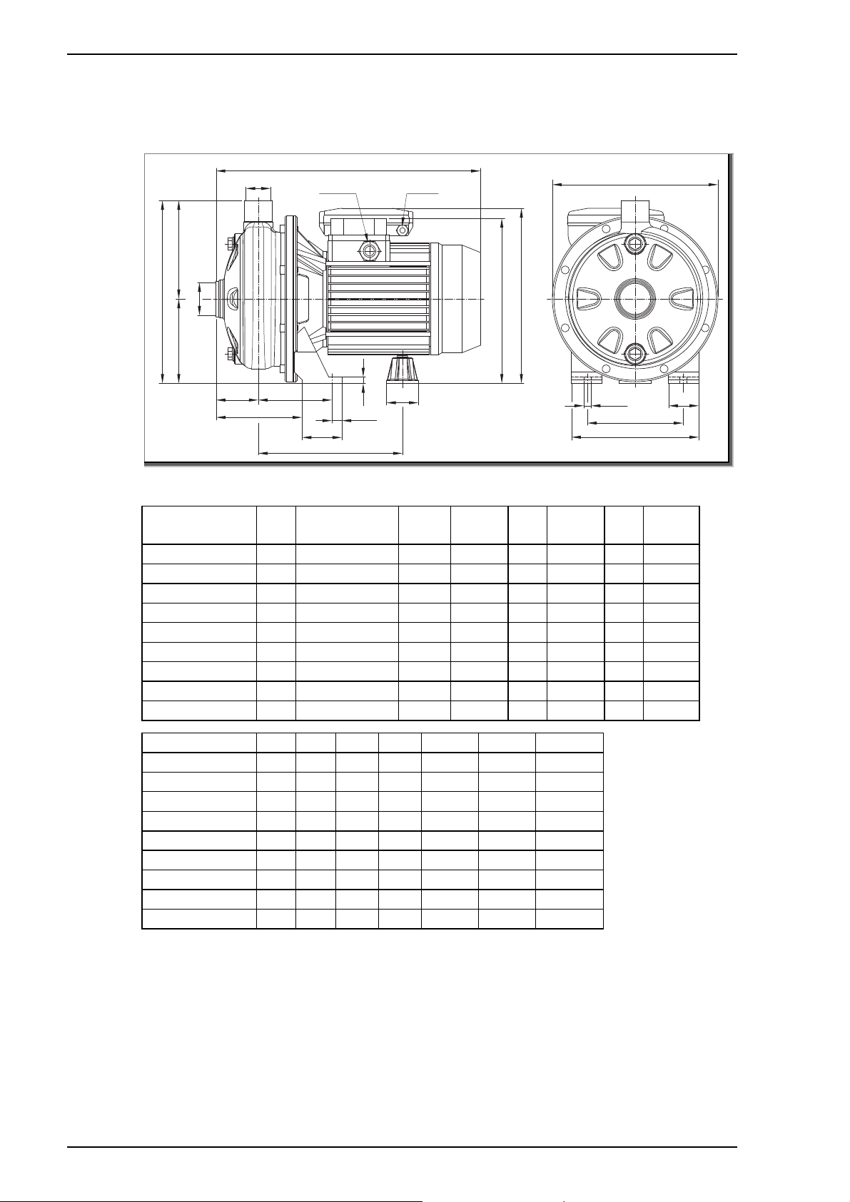
10.1 Maßzeichnung
VGX
B
Rp1
H2H1
H
DNA
53
R
WG64.022.004-P
V [3~] T [1~]
W
M
C
50 Hz
Typ A B
3~/1~
VGX 7/5 208 320/321 181 229,5 106 123,5 207 216
VGX 7/7 208 320/321 181 229,5 106 123,5 207 216
GX 9/10 208 320/321 198,5 229,5 106 123,5 207 216
GX 12/7 208 320/321 198,5 229,5 106 123,5 207 216
VGX 12/12 208 332/321 198,5 229,5 106 123,5 207 235
GX 12/20 232 371,5/346,5 198,5 250 118 132 237 248,5
GX 20/12 208 332/321 181 229,5 106 123,5 207 235
VGX 20/20 208 371,5/346,5 198,5 229,5 106 123,5 225 236,5
VGX 20/25 232 371,5/- 198,5 250 118 132 237 -
Typ M M1 N N1 R W DNA
VGX 7/5 50 38 120 160 108 92,5 Rp 1¼
VGX 7/7 50 38 120 160 108 92,5 Rp 1¼
GX 9/10 50 38 120 160 108 92,5 Rp 1¼
VGX 12/7 50 38 120 160 108 92,5 Rp 1¼
VGX 12/12 50 38 120 160 108 92,5 Rp 1¼
VGX 12/20 55 40 140 180 105,5 95 Rp 1¼
VGX 20/12 50 38 120 160 108 92,5 Rp 1½
VGX 20/20 55 40 140 180 105,5 95 Rp 1½
VGX 20/25 55 40 140 180 105,5 95 Rp 1½
12,5
A
H4 [1~]
H3 [3~]
Ø40
E
2-Ø9
N
N1
M1
C H H1 H2 H3 H4
28 DE 09|2018

Technische Daten
V
V
V
V
VGX
B
Rp1
H2H1
H
DNA
53
R
WG64.022.004-P
V [3~] T [1~]
W
M
C
60 Hz
Typ A B
3~/1~
VGX 7/7 208 320/321 181 229,5 106 123,5 207 216
VGX 7/10 208 320/321 181 229,5 106 123,5 207 216
VGX 7/15 208 332/321 181 229,5 106 123,5 207 216
VGX 12/10 208 320/321 181 229,5 106 123,5 207 216
VGX 12/15 208 332/321 181 229,5 106 123,5 207 216
VGX 12/20 232 359/347 198,5 229,5 106 123,5 225 249
VGX 20/15 208 320/321 181 229,5 106 123,5 207 216
VGX 20/20 208 359/347 198,5 229,5 106 123,5 225 237
VGX 20/30 232 359/- 198,5 250 118 132 237 -
Typ M M1 N N1 R W DNA
VGX 7/7 50 38 120 160 108 92,5 Rp 1¼
VGX 7/10 50 38 120 160 108 92,5 Rp 1¼
GX 7/15 50 38 120 160 108 92,5 Rp 1¼
VGX 12/10 50 38 120 160 108 92,5 Rp 1¼
VGX 12/15 50 38 120 160 108 92,5 Rp 1¼
GX 12/20 55 40 140 180 105,5 95 Rp 1¼
GX 20/15 50 38 120 160 108 92,5 Rp 1½
VGX 20/20 55 40 140 180 105,5 95 Rp 1½
GX 20/30 55 40 140 180 105,5 95 Rp 1½
E
12,5
A
H4 [1~]
H3 [3~]
Ø40
2-Ø9
N
N1
C H H1 H2 H3 H4
M1
09|2018 DE 29

Technische Daten
2 VGX
H2H1
H
DNA
Rp1
B
V [3~] T [1~]
H3 [3~]
H4 [1~]
A1 [1~]
FW
R
M
WG64.022.003-P
C
50 Hz
Typ A B
3~/1~
2 VGX 7/10 208 354/355 181 12,5 8 87 229 106 123 209
2 VGX 7/12 208 366/355 181 12,5 8 87 229 106 123 209
2 VGX 7/15 232 407/395,5 198,5 12,5 8 89 250 118 132 235
2 VGX 7/20 232 407,5/382,5 198,5 12,5 8 89 250 118 132 235
2 VGX 12/15 208 407/395,5 198,5 12,5 8 89 229 106 123 223
2 VGX 12/20 208 407,5/382,5 198,5 12,5 8 89 229 106 123 223
2 VGX 12/30 232 405/- 198,5 12,5 10 87 250 118 132 240
2 VGX 12/40 232 458/- 234,5 12,5 10 87 250 118 132 240
2 VGX 20/30 208 458/- 234,5 12,5 10 87 229 106 123 240
2 VGX 20/40 232 458/- 234,5 12,5 10 87 250 118 132 240
2 VGX 20/50 232 481/- 232,5 16 12 87 250 118 132 252
Typ H4 M M1 N N1 R W S DNA
2 VGX 7/10 216 50 38 120 160 142 92,5 9 Rp 1¼
2 VGX 7/12 235 50 38 120 160 142 92,5 9 Rp 1¼
2 VGX 7/15 248,5 55 40 140 180 141,5 95 9 Rp 1¼
2 VGX 7/20 248,5 55 40 140 180 141,5 95 9 Rp 1¼
2 VGX 12/15 236,5 55 40 140 180 141,5 95 9 Rp 1¼
2 VGX 12/20 236,5 55 40 140 180 141,5 95 9 Rp 1¼
2 VGX 12/30 - 65 40 140 180 143,5 109 9 Rp 1¼
2 VGX 12/40 - 65 40 140 180 143,5 109 9 Rp 1¼
2 VGX 20/30 - 65 40 140 180 143,5 109 9 Rp 1½
2 VGX 20/40 - 65 40 140 180 143,5 109 9 Rp 1½
2 VGX 20/50 - 68 50 160 210 143,5 108,5 12 Rp 1½
E
D
Ø40
2-ØS
N1
M1
N
A
C D E F H H1 H2 H3
30 DE 09|2018

Technische Daten
2 VGX
B
Rp1
H2H1
H
DNA
V [3~] T [1~]
H3 [3~]
H4 [1~]
A1 [1~]
FW
R
M
WG64.022.003-P
C
60 Hz
Typ A B
3~/1~
2 VGX 7/10 208 354/354 181 12,5 8 87 229 106 123
2 VGX 7/20 208 380/393 199 12,5 8 87 229 106 123
2 VGX 7/30 208 380/393 199 12,5 8 87 229 106 123
2 VGX 12/20 208 395/- 199 12,5 8 89 229 106 123
2 VGX 12/30 208 395/- 199 12,5 8 89 229 106 123
2 VGX 12/40 208 459/- 224/235 12,5 8 89 229 106 123
2 VGX 20/40 208 457/- 224/235 12,5 8 87 229 106 123
2 VGX 20/40 R 208 457/- 224/235 12,5 8 87 229 106 123
2 VGX 20/50 208 480/- 233 16 12 87 241 118 123
Typ H3 H4 M M1 N N1 R W S DNA
2 VGX 7/10 208 216 50 38 120 160 142 93 9 Rp 1¼
2 VGX 7/20 225 242 55 40 140 180 140 95 9 Rp 1¼
2 VGX 7/30 225 242 55 40 140 180 140 95 9 Rp 1¼
2 VGX 12/20 225 - 55 40 140 180 142 95 9 Rp 1¼
2 VGX 12/30 225 - 55 40 140 180 142 95 9 Rp 1¼
2 VGX 12/40 230 - 65 40 140 180 146 109 9 Rp 1¼
2 VGX 20/40 230 - 65 40 140 180 144 109 9 Rp 1½
2 VGX 20/40 R 230 - 65 40 140 180 144 109 9 Rp 1½
2 VGX 20/50 259 - 68 50 160 210 144 109 12 Rp 1½
E
D
Ø40
2-ØS
N1
M1
N
A
C D E F H H1 H2
09|2018 DE 31

Technische Daten
MTX
Abb. 1
10090
190
Abb. 2
100
H1
D1
D1
B
D2
H3 [3~]
H4 [1~]
F
R
W
108
D2
8
57
C
B
Ø20
H4 [1~]
L
G 1/8
G 1/8
40 Ø9
108
148
165
L
G 1/8
H3 [3~]
H
FW
R
Typ D1 D2 B C F R W H3 H4 L
3-20 1~ Rp 1 Rp 1 360 171 103 151,5 88 ÷ 97 - 200 86,5
3-20 3~ Rp 1 Rp 1 360 171 103 151,5 88 ÷ 97 192 - -
3-30 1~ Rp 1 Rp 1 360 171 103 151,5 88 ÷ 97 - 200 86,5
3-30 3~ Rp 1 Rp 1 360 171 103 151,5 88 ÷ 97 192 - -
3-40 1~ Rp 1 Rp 1 384 171 127 175,5 88 ÷ 97 - 200 86,5
3-40 3~ Rp 1 Rp 1 384 171 127 175,5 88 ÷ 97 192 - -
3-50 1~ Rp 1 Rp 1 408 171 151 199,5 88 ÷ 97 - 200 86,5
3-50 3~ Rp 1 Rp 1 408 171 151 199,5 88 ÷ 97 192 - -
3-60 1~ Rp 1 Rp 1 432 171 175 223,5 88 ÷ 97 - 219 106
3-60 3~ Rp 1 Rp 1 444 171 175 223,5 88 ÷ 97 192 - -
3-70 1~ Rp 1 Rp 1 493 198 199 247,5 88 ÷ 97 - 226 112
3-70 3~ Rp 1 Rp 1 518 198 199 247,5 88 ÷ 97 209 - -
3-80 1~ Rp 1 Rp 1 517 198 223 271,5 88 ÷ 97 - 226 112
3-80 3~ Rp 1 Rp 1 542 198 223 271,5 88 ÷ 97 209 - -
3-90 1~ Rp 1 Rp 1 541 198 247 295,5 88 ÷ 97 - 226 112
3-90 3~ Rp 1 Rp 1 567 198 247 295,5 88 ÷ 97 209 - -
13
W1
W2
M1 S1
N1
N2
WG64.022.002-P
G 1/8
32 DE 09|2018

Typ D1 D2 B C F R W H3 H4 L
5-20 1~ Rp 1¼ Rp 1 360 171 103 151,5 88 ÷ 97 - 200 86,5
5-20 3~ Rp 1¼ Rp 1 360 171 103 151,5 88 ÷ 97 192 - -
5-30 1~ Rp 1¼ Rp 1 360 171 103 151,5 88 ÷ 97 - 200 86,5
5-30 3~ Rp 1¼ Rp 1 360 171 103 151,5 88 ÷ 97 192 - -
5-40 1~ Rp 1¼ Rp 1 384 171 127 175,5 88 ÷ 97 - 219 106
5-40 3~ Rp 1¼ Rp 1 396 171 127 175,5 88 ÷ 97 192 - -
5-50 1~ Rp 1¼ Rp 1 445 198 151 199,5 88 ÷ 97 - 226 112
5-50 3~ Rp 1¼ Rp 1 470 198 151 199,5 88 ÷ 97 209 - -
5-60 1~ Rp 1¼ Rp 1 469 198 175 223,5 88 ÷ 97 - 226 112
5-60 3~ Rp 1¼ Rp 1 494 198 175 223,5 88 ÷ 97 209 - -
5-70 1~ Rp 1¼ Rp 1 493 198 199 247,5 88 ÷ 97 - 226 112
5-70 3~ Rp 1¼ Rp 1 518,5 198 199 247,5 88 ÷ 97 209 - -
5-80 1~ Rp 1¼ Rp 1 565 - 223 325,5 117,5 - 231 112
5-80 3~ Rp 1¼ Rp 1 542,5 198 223 271,5 88 ÷ 97 209 - -
5-90 1~ Rp 1¼ Rp 1 589 - 247 349,5 117,5 - 231 112
5-90 3~ Rp 1¼ Rp 1 566,5 198 247 295,5 88 ÷ 97 209 - -
Typ H H1 W1 W2 M1 N1 N2 S1
5-80 1~ 90 190 125 155 30 140 170 9
5-90 1~ 90 190 125 155 30 140 170 9
Typ D1 D2 B C F R W H3 H4 L
10-20 1~ Rp 1½ Rp 1¼ 379 175 118 170,5 92 ÷ 101 - 200 86,5
10-20 3~ Rp 1½ Rp 1¼ 379 175 118 170,5 92 ÷ 101 192 - -
10-30 1~ Rp 1½ Rp 1¼ 416 202 118 170,5 92 ÷ 101 - 226 112
10-30 3~ Rp 1½ Rp 1¼ 441 202 118 170,5 92 ÷ 101 209 - -
10-40 1~ Rp 1½ Rp 1¼ 446 202 148 200,5 92 ÷ 101 - 226 112
10-40 3~ Rp 1½ Rp 1¼ 471,5 202 148 200,5 92 ÷ 101 209 - -
10-50 1~ Rp 1½ Rp 1¼ 524 - 178 284,5 121,5 - 231 112
10-50 3~ Rp 1½ Rp 1¼ 501,5 202 178 230,5 92 ÷ 101 209 - -
10-60 1~ Rp 1½ Rp 1¼ 554 - 208 314,5 121,5 - 231 112
10-60 3~ Rp 1½ Rp 1¼ 531,5 202 208 260,5 92 ÷ 101 209 - -
Typ H H1 W1 W2 M1 N1 N2 S1
10-50 1~ 90 190 125 155 30 140 170 9
10-60 1~ 90 190 125 155 30 140 170 9
Typ D1 D2 B C F R W H3 H4 L
18-20 1~ Rp 2 Rp 1½ 442 205 141 196,5 95 ÷ 104 - 226 112
18-20 3~ Rp 2 Rp 1½ 467,5 205 141 196,5 95 ÷ 104 209 - -
18-30 1~ Rp 2 Rp 1½ 490 - 141 250,5 124,5 - 231 112
18-30 3~ Rp 2 Rp 1½ 467,5 205 141 196,5 95 ÷ 104 209 - -
18-40 3~ Rp 2 Rp 1½ 565 - 178,5 288 124,5 214 - -
18-50 3~ Rp 2 Rp 1½ 615 - 216 315 114 241 - -
18-60 3~ Rp 2 Rp 1½ 652 - 253,5 352,5 114 241 - -
Typ H H1 W1 W2 M1 N1 N2 S1
18-30 1~ 90 190 125 155 30 140 170 9
18-40 3~ 90 190 125 155 30 140 170 9
18-50 3~ 100 200 140 170 35 160 192 11
18-60 3~ 100 200 140 170 35 160 192 11
Technische Daten
09|2018 DE 33

Technische Daten
10.2 Kennlinie
50 Hz
VGX 7
H [m]
35
7/7
30
25
7/5
20
15
10
5
0
012
345
Q [m³/h]
Q [l/min]
010203040
50 60 70 80
90
KL64.022.001-P
VGX 9
H [m]
70
60
50
40
9/10
30
20
10
0
0 1 2 3 4 5 6 Q [m³/h]
0 10 20 30 40 50 60 70 80 90 100 Q [l/min]
KL64.022.003-P
34 DE 09|2018

Technische Daten
VGX 12
H [m]
45
12/20
40
35
12/12
30
25
12/7
20
15
10
5
0
02
0204060
46
80 100 120 140 160
8 10 Q [m³/h]
Q [l/min]
KL64.022.004-P
VGX 20
H [m]
45
20/25
40
20/20
35
30
25
20/12
20
15
10
5
0
02 4 6
0 20 40 60 80 100 120 140 160 180 200
81012
220
Q [m³/h]
14
Q [l/min]
KL64.022.006-P
09|2018 DE 35

Technische Daten
2 VGX 7
H [m]
80
70
7/20
60
7/15
50
7/12
7/10
40
30
20
10
0
012
0 10203040
3 4 5 Q [m³/h]
50 60 70 80 Q [l/min]
KL64.022.002-P
2 VGX 12
H [m]
80
12/40
70
12/30
60
12/20
50
12/15
40
30
20
10
0
0246810
20 40 60 80 100 120 140 160
Q [m³/h]
Q [l/min]0
KL64.022.005-P
36 DE 09|2018

Technische Daten
2 VGX 20
H [m]
80
20/50
70
20/40
60
20/30
50
40
30
20
10
0
0 2 4 6 8 10 12 Q [m³/h]
Q [l/min]200180160140120100806040200
KL64.022.007-P
09|2018 DE 37

Technische Daten
60 Hz
VGX 7
H [m]
50
7/15
40
7/10
30
7/7
20
10
0
0 20 40 60 80 100 Q [l/min]
0 1 2 3 4 5 6 Q [m³/h]
KL64.022.012-P
VGX 12
H [m]
50
12/20
40
12/15
30
12/10
20
10
0
0
01234
40 80 120 160 200 Q [l/min]
5678
910
11
12
13 Q [m³/h]
KL64.022.013-P
38 DE 09|2018

Technische Daten
VGX 20
H [m]
40
20/30
20/20
30
20/15
20
10
0
0
50 100 150 200 250 Q [l/min]
0 2 4 6 8 10 12 14 16 Q [m³/h]
KL64.022.014-P
09|2018 DE 39

Technische Daten
2 VGX 7
H [m]
80
7/30
60
7/20
7/10
40
20
0
0 20 40 60 80 100 Q [l/min]
0 1 2 3 4 5 6 Q [m³/h]
KL64.022.015-P
2 VGX 12
H [m]
80
12/40
12/30
60
12/20
40
20
012040 16080 200 Q [l/min]
0 2 4 6 Q [m³/h]
81012
KL64.022.016-P
40 DE 09|2018

Technische Daten
2 VGX 20
H [m]
80
20/50
70
20/40
60
20/40 R
50
40
30
0 50 100 150 200 250 Q [l/min]
02 4 6810
12
14
Q [m³/h]
16
KL64.022.017-P
09|2018 DE 41

Technische Daten
MTX 3
H [m]
120
3-90
100
3-80
3-70
80
3-60
60
3-50
3-40
40
3-30
3-20
20
0
0
12345
806040200
Q [m³/h]
Q [l/min]
KL64.022.008-P
MTX 5
H [m]
120
5-90
100
5-80
5-70
80
5-60
5-50
60
5-40
40
5-30
5-20
20
0
0
0 25 50 75 100 125
12 3456 7 8
Q [m³/h]
Q [l/min]
KL64.022.009-P
42 DE 09|2018

Technische Daten
MTX 10
H [m]
80
10-60
10-50
60
10-40
40
10-30
20
0
0
2
0 50 100
46
810
150 200 250
12
14 16
KL64.022.010-P
Q [m³/h]
Q [l/min]
MTX 18
H [m]
80
18-60
18-50
60
18-40
40
18-30
18-20
20
0
0 5 10 15
0 100 200
20 25 30
300 400 500
Q [m³/h]
Q [l/min]
KL64.022.011-P
09|2018 DE 43

Technische Daten
10.3 Explosionszeichnung
VGX
Drehstrom-Ausführung
3-phase version
833.1
833.5
836
833.6
412.1
551
230.1
922
502.1
101
412.4
903.1
903
412.4
914
903.1
903
837
433
833.4
836
833.2
838
833.5
813
161
421.1
833.1
812.1
600
833.8
833.9
183
819
940
321.1
905
832
831
421.2
812.2
504
321.2
525
WG64.022.005-P
44 DE 09|2018

Technische Daten
2 VGX
Drehstrom-Ausführung
3-phase version
502.1
101
412.4
903.1
903
903.1
903
833.1
833.5
836
833.6
162
412.4
922
230.2
914
174.1
521
108
502.2
833.4
836
837
833.2
838
833.5
813
412.2
230.1
833.1
174.2
551
433
600
412.1
833.8
833.9
161
421.1
905
321.2
321.1
812.1
832
831
421.2
812.2
504
940
525
183
819
WG64.022.006-P
09|2018 DE 45

Technische Daten
A
A
A
101 Gehäuse 600 Zugentlastung
108 Stufengehäuse 812.1
161 Dichtungsgehäuse 812.2 B-seitiges Lagerschild
162 Saugdeckel 813
174.1 Leitschaufeleinsatz 819 Welle mit Rotor
174.2 Leitschaufeleinsatz 831 Lüfterrad
183 Motorfuß 832 Lüfterhaube
230.1 Laufrad 833.1 Klemmkastendeckel
230.2 Laufrad 833.2
321.1 Kugellager A-seitig 833.4
321.2 Kugellager B-seitig 833.5
412.1 O-Ring für Gehäuse 833.6 Kabelverschraubung
412.2
O-Ring für
Stufengehäuse
412.4
O-Ring für
Verschlussschraube
421.1 Radialwellendichtring 836 Klemmenleiste
421.2 Radialwellendichtring 837 Kondensator
433 Gleitringdichtung 838 Motorschutzschalter
502.1 Spaltring 903 Verschlussschraube
502.2 Spaltring 903.1
504
bstandsring 905 Motorspannschraube
521 Stufenhülse 914
525
551
bstandshülse 922 Laufradmutter
Abstandsring zu Gleitringdichtung mit Balg
-seitiges Lagerschild
Stator mit
Motorgehäuse
Klemmkastenoberteil
mit Kondensatorrohr
KlemmkastendeckelDichtung, oben
KlemmkastendeckelDichtung, unten
833.8
833.9
Kabelverschraubung
Kabeldurchführung
Scheibe für
Verschlussschraube
Innensechskantschra
ube
940 Passfeder
46 DE 09|2018

Technische Daten
MTX
833.1
833.4
836
837
833.2
833.5
903.1
412.4
101
412.4
903.1
903.2
903.2
523
174.4
551
901
598
1~
932
600
833.8
833.9
838
230
554
521.5
551
174.2
433
521.1
521.3
412.16
521.2
161
230
507
521.4
174.3
812.1
521.4
230
421.1
521.4
321.1
174.1
836
230
819
833.1
813
521.4
833.5
183
812.2
831
321.2
833.6
504
832
421.2
905
09|2018 DE 47

Technische Daten
A
101 Gehäuse 598 Blech
161 Dichtungsgehäuse 600 Zugentlastung
183 Motorfuß 812.1 A-seitiges Lagerschild
174.1 Leitschaufeleinsatz 812.2 B-seitiges Lagerschild
174.2 Leitschaufeleinsatz 813
174.3 Leitschaufeleinsatz 819 Welle mit Rotor
174.4 Leitschaufeleinsatz 831 Lüfterrad
230 Laufrad 832 Lüfterhaube
321.1 Kugellager A-seitig 833.1 Klemmkastendeckel
321.2 Kugellager B-seitig 833.2
412.1 O-Ring 833.4
421.2 O-Ring 833.5
412.4 O-Ring 833.6 Kabelverschraubung
433 Gleitringdichtung 833.8 Kabelverschraubung
504
507 Spritzring 836 Klemmenleiste
521.1 Stufenhülse 837 Kondensator
521.2 Stufenhülse 838 Motorschutzschalter
521.3 Stufenhülse 901 Schraube
521.4 Stufenhülse 903.1 Verschlussschraube
521.5 Stufenhülse 903.2 Verschlussschraube
523 Stufenhülse 905 Motorspannschraube
551 Abstandsring 914
554 Unterlegscheibe 932 Sicherungsring
Stator mit
Motorgehäuse
Klemmkastenoberteil
mit Kondensatorrohr
KlemmkastendeckelDichtung, oben
KlemmkastendeckelDichtung, unten
bstandsring 833.9 Kabelverschraubung
Innensechskantschraube
48 DE 09|2018

11 Index
A
Aufstellung 16
Außerbetriebnahme 19, 20
B
Bestimmungsgemäße Verwendung 7
E
Elektrischer Anschluss 17
Entsorgung 25
Index
I
Inbetriebnahme 19
Installation 15
L
Lagerung 14
R
Rohrleitung 16
Ersatzteile 8
F
Fehlanwendungen 7
Frost 12
G
Gewährleistung 24
Gleitringdichtung 21
S
Störungen 10, 21
T
Technische Daten 26
Transport 14
W
Wartung 24
09|2018 DE 49


EN Translation of original operation manual
VGX, 2VGX, MTX
EN
WG64.022.008-P

SPECK Pumpen Verkaufsgesellschaft GmbH
Hauptstraße 3
91233 Neunkirchen am Sand, Germany
Phone +49 9123 949-0
Fax +49 9123 949-260
info@speck-pumps.com
www.speck-pumps.com
All rights reserved.
Contents may not be distributed, duplicated, edited or
transferred to third parties without the written
permission of SPECK Pumpen Verkaufsgesellschaft
GmbH.
This document and all attached documents are not
subject to update service!
Subject to technical modifications!
2 EN 09|2018

Table of contents
Table of contents
1 About this document ....................................................................... 5
1.1 Using this manual ...................................................................... 5
1.2 Target group.............................................................................. 5
1.2.1 Symbols and means of representation .................................. 5
2 Safety ................................................................................................ 7
2.1 Intended use ............................................................................. 7
2.1.1 Possible misuse .................................................................... 7
2.2 Personnel qualification .............................................................. 7
2.3 Safety regulations ..................................................................... 8
2.4 Protective equipment ................................................................ 8
2.5 Structural modifications and spare parts ................................... 8
2.6 Signs ......................................................................................... 8
2.7 Residual risk.............................................................................. 8
2.7.1 Rotating parts ........................................................................ 8
2.7.2 Electrical energy .................................................................... 9
2.7.3 Hot surfaces .......................................................................... 9
2.7.4 Hazardous materials ............................................................. 9
2.8 Faults ........................................................................................ 9
2.9 Preventing material damage ................................................... 10
2.9.1 Leakage and pipe breakage ................................................ 10
2.9.2 Dry running .......................................................................... 10
2.9.3 Cavitation ............................................................................ 10
2.9.4 Overheating ......................................................................... 10
2.9.5 Pressure surges .................................................................. 10
2.9.6 Blockages in the pump ........................................................ 10
2.9.7 Drainage.............................................................................. 11
2.9.8 Risk of frost ......................................................................... 11
2.9.9 Safe use of the product ....................................................... 11
3 Description ..................................................................................... 12
3.1 VGX/2VGX design .................................................................. 12
3.2 MTX design ............................................................................. 12
3.3 Material ................................................................................... 12
3.4 Design ..................................................................................... 12
4 Transport and intermediate storage ............................................. 13
09|2018 EN 3

Table of contents
4.1 Transport ................................................................................. 13
4.2 Storage ................................................................................... 13
4.3 Returns ................................................................................... 13
5 Installation ...................................................................................... 14
5.1 Installation ............................................................................... 14
5.1.1 Installation ........................................................................... 14
5.1.2 There must be ground drainage .......................................... 14
5.1.3 Ventilation and aeration ....................................................... 14
5.2 Pipes ....................................................................................... 14
5.2.1 Dimensioning pipework ....................................................... 14
5.2.2 Laying pipework .................................................................. 14
5.3 Installation ............................................................................... 15
5.3.1 Installing the pump and connecting it to the pipework ......... 15
5.4 Electrical connection ............................................................... 16
5.4.1 Connection plan .................................................................. 17
6 Commissioning/Decommissioning .............................................. 18
6.1 Commissioning ........................................................................ 18
6.1.1 Checking how easily the pump rotates ................................ 18
6.1.2 Switching the pump on ........................................................ 18
6.2 Decommissioning .................................................................... 19
7 Faults .............................................................................................. 20
7.1 Overview ................................................................................. 20
8 Maintenance ................................................................................... 23
8.1 Warranty ................................................................................. 23
8.2 Service addresses ................................................................... 23
9 Disposal .......................................................................................... 24
10 Technical data ............................................................................ 25
10.1 Dimensional drawing ............................................................... 28
10.2 Characteristics ........................................................................ 34
10.3 Exploded drawing .................................................................... 44
11 Index ............................................................................................ 49
4 EN 09|2018

jury
1 About this document
1.1 Using this manual
This manual is a component of the pump/unit. The pump/unit was
manufactured and tested according to the generally accepted
rules of technology. However, if the pump/unit is used incorrectly,
not serviced enough or tampered with, danger to life and limb or
material damage could result.
Read the manual carefully before use.
Keep the manual during the service life of the product.
Provide access to the manual for operating and service
personnel at all times.
Pass the manual on to any future owners or operators of the
product.
About this document
1.2 Target group
This instruction manual is intended for qualified professionals.
1.2.1 Symbols and means of representation
Warnings are used in this manual to warn you of personal injury.
Always read and observe warnings.
DANGER
Danger for people.
Non-observance results in death or serious in
WARNING
Danger for people.
Non-observance can result in death or serious injury.
CAUTION
.
Danger for people.
Non-observance can result in light to moderate injury.
NOTICE
Notes to prevent material damage, for better understanding or to
optimise the workflow.
Important information and technical notes are specially marked to
explain correct operation.
09|2018 EN 5

About this document
Symbol Meaning
1.
2.
Instructions for a one-step action.
Directions for a multi-step action.
Observe the order of the steps.
6 EN 09|2018

2 Safety
2.1 Intended use
The pump is suitable for water treatment, water supply, cooling
units, equipment engineering and pressure boosting. Clean water,
and no aggressive media, should be handled.
Safety
Observing the following information is vital for intended use:
• This manual
The pump/unit may only be operated within the application limits
and characteristics, as specified in this manual.
Any other use or use exceeding this is not an intended use and
must first be authorised by the manufacturer/supplier.
2.1.1 Possible misuse
• Installing the pump/unit with stress on the pipes.
• Using the pump/unit beyond the operating limits specified in
the pump data sheet, e.g. excessive system pressure.
• Opening and servicing of the pump/unit by unqualified
personnel.
2.2 Personnel qualification
This unit can be used by children aged 8 and over as well as by
persons with limited physical, sensory or mental capacity or by
people with a lack of experience or knowledge, provided that they
are supervised or have been instructed in the safe use of the unit
and understand the resulting dangers. Children may not play with
the unit. Cleaning and user maintenance may not be carried out
by children without supervision.
Ensure that the following work is only performed by trained
professionals with the following qualifications:
– For mechanical work, for example replacing ball bearings
or mechanical seals: qualified mechanics.
– For work on the electric system: electricians.
Ensure that the following requirements are fulfilled:
– Personnel who do not yet have the appropriate
qualifications must receive the required training before
being allowed to work on the system.
09|2018 EN 7

Safety
– The personnels' responsibilities, for example working on
the product, electric equipment or hydraulic systems, are
set based on their qualifications and the job description.
– The personnel have read this manual and understand the
necessary working steps.
2.3 Safety regulations
The operator of the system is responsible for the adherence to all
relevant statutory regulations and guidelines.
Observe the following regulations when using the pump/unit:
– This manual
– Warning and information signs on the product
– The valid national regulations for accident prevention
– The internal occupational, operational and safety
regulations of the operator
2.4 Protective equipment
Reaching into moving parts, e.g. impeller fan, can cause serious
injury.
Never operate the pump/unit without protective covers.
2.5 Structural modifications and spare parts
Alterations or modifications can affect operational safety.
Never modify or alter the pump/unit without the
manufacturer's permission.
Only use original spare parts and accessories authorised by
the manufacturer.
2.6 Signs
Ensure that all the signs on the complete pump/unit remain
legible.
2.7 Residual risk
2.7.1 Rotating parts
There is a risk of shearing and crushing due to exposed rotating
parts.
Only perform servicing when the pump/unit is not in
operation.
Prior to servicing, ensure the pump/unit cannot be switched
back on.
8 EN 09|2018

Immediately after finishing servicing, reattach or reactivate all
protective equipment.
2.7.2 Electrical energy
Electrical protective earth conductors which were not installed
correctly can also result in electric shocks, for example due to
oxidation or cable breakage.
Observe VDE and utility company regulations.
Before working on the electrical system, take the following
measures:
– Disconnect system from the power supply.
– Attach a warning sign: “Do not switch on! The system is
being worked on.”
– Ensure that the system is free of voltage.
Check the electrical system regularly to ensure it is in proper
working condition.
Safety
2.7.3 Hot surfaces
During operation the pump can become very hot. Therefore there
is a danger of being burned.
Do not touch the pump during operation.
Allow the pump/unit to cool down before servicing it.
2.7.4 Hazardous materials
Ensure that leaks of dangerous pumped fluids/gases are led
away without endangering people or the environment.
Decontaminate the pump completely during disassembly.
2.8 Faults
In case of a fault, immediately switch the pump off and
remove it from operation.
Have all faults repaired immediately.
Seized pump
If a pump seizes, and is switched on several times repeatedly, the
motor can be damaged. Observe the following points:
Do not switch the pump/unit on repeatedly.
Turn the motor shaft by hand. .
Clean pump.
09|2018 EN 9

Safety
2.9 Preventing material damage
2.9.1 Leakage and pipe breakage
If the pipe forces are exceeded, leaks can occur at the screwed
connection or the pump itself.
Do not use the pump as a fixed point for the pipe line.
Connect pipes free of load and mount them elastically. Install
compensators if necessary.
If the pump leaks, the unit may not be operated and must be
2.9.2 Dry running
Various components can be damaged within seconds due to dry
running.
Do not allow the pump to run dry.
disconnected from the mains power supply.
Purge air from pump prior to start-up.
2.9.3 Cavitation
Pipes which are too long increase resistance. This results in risk
of cavitation.
Ensure that the suction line does not leak.
Observe the maximum pipe length.
Open the valve on the suction side completely.
2.9.4 Overheating
The following factors can lead to the pump overheating:
• Insufficient cooling of the pump.
• Closed valve in the pressure line.
Do not let the pump run dry.
Do not operate the pump with closed valves.
2.9.5 Pressure surges
Valves which close suddenly can cause pressure surges which far
exceed the maximum permissible housing pressure of the pump.
Avoid valves which close suddenly or, if present, close them
slowly.
2.9.6 Blockages in the pump
Dirt particles can clog and block the pump.
Check how easily the pump rotates before starting it up and
after longer idle or storage periods.
10 EN 09|2018

2.9.7 Drainage
An insufficient drain gap can damage the motor.
Do not block or seal the drain gap between the pump
housing and the motor.
2.9.8 Risk of frost
Drain the pump/unit and pipes at risk of freezing in plenty of
time.
Remove the pump/unit during periods of frost and store it in a
dry room.
2.9.9 Safe use of the product
Safe use of the product is no longer guaranteed in the following
instances:
If the pipework is not in proper condition.
Safety
If the pump seizes. .
If protective devices are damaged or missing, e.g. protection
against accidental contact.
If there is stress on the pump/unit or pipes during installation.
09|2018 EN 11

Description
g
3 Description
3.1 VGX/2VGX design
The pumps in the VGX/2VGX range are monoblock pumps with
surface-cooled motors, extended motor shafts to accommodate
the impellers, shaft seals in the form of mechanical seals and are
configured for constant operation.
3.2 MTX design
The pumps in the MTX range are multistage, horizontal centrifugal
pumps with surface-cooled motors, extended motor shafts to
accommodate the impellers, shaft seals in the form of mechanical
seals and are configured for constant operation.
3.3 Material
VGX
Housin
stainless steel AISI 304
Impeller stainless steel AISI 304
Shaft stainless steel AISI 303
Motor frame aluminium
Mechanical seal carbon/ceramic*
O-rings NBR*
Motor casing aluminium
* other designs on request
MTX
Housing stainless steel AISI 304
Impeller stainless steel AISI 304
Shaft stainless steel AISI 304
Seal carrier stainless steel AISI 304
Motor frame aluminium
Mechanical seal carbon/ceramic*
O-rings EPDM*
Motor casing aluminium
* other designs on request
3.4 Design
Impeller closed
Shaft seal mechanical seal
Bearing
12 EN 09|2018
Sealed deep groove ball
bearing

Transport and intermediate storage
4 Transport and intermediate storage
4.1 Transport
Check the delivery conditions.
– Check the packaging for transport damage.
– Determine damages, document them with photographs
and contact the distributor.
4.2 Storage
NOTICE
Corrosion is possible due to storage in humid conditions with
fluctuating temperatures!
Condensation can corrode windings and metal parts.
Store the pump/unit in a dry environment at a temperature
which is as constant as possible.
NOTICE
There is a risk of damage to the winding and entry of foreign
matter due to open ports!
Do not remove the port covers until the pipes are ready to be
connected.
NOTICE
Damage or loss of individual parts!
Do not open the original packaging until installation or keep
individual parts in the original packaging until installation.
4.3 Returns
– Drain the pump/unit completely.
– Rinse and clean the pump/unit with clear water.
– Pack the pump/unit in a box and send it to the specialist
retailer or manufacturer.
09|2018 EN 13

Installation
5 Installation
5.1 Installation
5.1.1 Installation
The pump must be installed dry and in a horizontal position.
5.1.2 There must be ground drainage
Calculate the size of the ground drain according to the
following criteria:
– Maximum flow rate of the pump.
5.1.3 Ventilation and aeration
Ensure sufficient ventilation and aeration. The ventilation and
aeration must ensure the following conditions:
– Prevention of condensation.
– Cooling of the pump motor and other system components,
for example switch cabinets and control units.
– Limitation of the ambient temperature to maximum 40 °C.
5.2 Pipes
5.2.1 Dimensioning pipework
The pipework with threaded connection must be provided
according to the discharge outlet or larger.
Use metal or plastic for pipework in fixed installations.
Plastic hoses may be used in temporary installations. These
must withstand the pressure or vacuum of the pump.
5.2.2 Laying pipework
Keep the pressure lines as short and straight as possible.
Avoid sudden changes to the cross-section and direction.
Assemble a non-return valve in the pressure line.
Do not use the pump as a fixing point for the pipework.
Prior to assembly, clean the components and attach them to
the pump tension free using suitable sealing materials.
14 EN 09|2018

Installation
g
5.3 Installation
5.3.1 Installing the pump and connecting it to the pipework
1. Install the pump in a horizontal and dry position.
NOTICE
The motor can be damaged due to insufficient drainage!
Do not block or seal the drain gap between the pump housing
and the motor.
NOTICE
If it is sealed incorrectly, the thread can be damaged and the
sealin
effect can be reduced!
NOTICE
The pump can be damaged by unauthorised mechanical strains
being placed on the pump!
Take the pipe up directly before the pump and connect it free
of tension.
2. Connect the pipe free of tension according to the VDMA
standard sheet 24277. Use compensators if necessary.
3. Ensure that any leaks cannot cause consequential damage.
Install a suitable retainer if necessary.
WARNING
Pumped fluid hazardous to health!
Observe legal regulations regarding the disposal of media
hazardous to health.
09|2018 EN 15

Installation
y
5.4 Electrical connection
WARNING
Risk of electric shock due to incorrect connections!
Electrical connections must always be carried out by
authorised specialists.
Observe VDE and utility company regulations.
Install a disconnecting device with at least a 3 mm contact
Protect power supply with a ground fault circuit interrupter,
Only use suitable pipe types according to regional
gap per pole to interrupt the power supply.
nominal residual current I
FN
regulations.
≤ 30 mA.
Adjust minimum diameter of the electrical pipes to
accommodate the motor output and pipe length.
Do not bend or squash the pipes.
If hazardous situations can occur, provide an emergency off
switch according to DIN EN 809. The builder/operator must
make a decision according to this standard.
WARNING
Risk of electric shock due to voltage on the housing!
A correctly set motor protection switch must be installed in
pumps with a three-phase motor. In doing so, observe the
values on the motor name plate.
NOTE
During connection please be aware that the pump may only be
operated once the system has been filled with water. Otherwise
the pump ma
run dry and cause damage.
The motor has thermal overload protection. Moreover, the
motor has an automatic starter. Thus this can be connected
directly to the power supply.
16 EN 09|2018

5.4.1 Connection plan
M
1~
COMMON
MAIN
AUX
U2
W2
Installation
P
PE
V1
U1
C
L1
N
V2
V1
U1
W1
WG27.50.095-P
M
3~
V2
U2
W2
W1
U2
V1
U1
W2
230/400 V three phase motors are connected in delta for 230 V
and in star for 400 V.
PE
L1
L2
L3
V1
U1
W1
M
3~
V2
U2
W2
V2
U2
W2
W1
V1
U1
PE
L1
L2
L3
09|2018 EN 17

Commissioning/Decommissioning
6 Commissioning/Decommissioning
6.1 Commissioning
NOTICE
The pump/unit can be damaged if it runs dry!
Ensure that the pump/unit is always full of water. This also
applies to checking the rotation direction.
6.1.1 Checking how easily the pump rotates
After longer idle periods, the pump must be checked for how
easily it rotates while it is switched off.
Place a screwdriver in the groove on the end of the motor
shaft on the fan side and turn it.
– or –
If there is not a groove on the end of the motor shaft:
Remove the fan cover and turn the fan wheel manually in the
motor rotation direction.
6.1.2 Switching the pump on
1. Open the valves completely.
NOTICE
The pump can be damaged if it runs dry!
Purge air from the pump and suction line.
2. Switch the pump/unit on.
NOTICE
If the pump has a three-phase motor and it turns in the wrong
direction, the pump/unit is louder and has a lower capacity.
3. For three-phase motors: Ensure that the motor turns in the
direction of the arrow labeled on the fan hood. If the motor
rotates in the wrong direction, notify an electrician.
4. Check the mechanical seal for leaking.
18 EN 09|2018

6.2 Decommissioning
1. Turn the pump off.
2. Close the valves on the suction and pressure sides.
3. Drain the pump and pipes.
4. If there is a chance of frost, store the pump and pipes
sensitive to frost in a dry place, secure from frost.
Commissioning/Decommissioning
09|2018 EN 19

Faults
7 Faults
NOTICE
It is normal for a few drops of water to escape from the
mechanical seal from time to time. This is especially true during
the break-in period.
Depending on the water quality and number of operating hours,
the mechanical seal can begin to leak.
If water leaks constantly, have the mechanical seal replaced
by a qualified technician.
7.1 Overview
Problem: Motor doesn’t start
Possible cause Solution
Motor protection triggered.
Wait for the motor winding to
cool down and the motor
protection to turn back on
(1~).
Check the motor protection
switch (3~).
No voltage. Check the power supply.
Burnt fuse Replace the fuse; if the
problem recurs check the
electrical connection.
Motor or capacitor faulty. Replace the motor or
capacitor.
Problem: No flow rate; motor turns
Possible cause Solution
Shut-off valve closed. Open shut-off valve.
Pump is not filled with
Fill pump.
media.
Leak in the unit/pipe. Check and repair pipework.
20 EN 09|2018

Faults
Problem: Too low a flow rate in the pump.
Possible cause Solution
Incorrect direction of rotation
(3~).
Check the electrical
connections using the
operating manual.
Pump or pipework dirty or
Check and clean it.
partly blocked.
Problem: Pump constantly turns off
Possible cause Solution
Motor protection triggered. Check pump for impurities.
Clean pump and pump parts.
Pumped media is too
viscous.
Pump is running outside of
the characteristics.
Correct the pump‘s operating
point.
Problem: Leak between pump and motor
Possible cause Solution
Shaft seal worn or
damaged.
Pump running dry. Replace the shaft seal.
Replace the shaft seal.
09|2018 EN 21

Faults
g
Problem: Pump vibrates and/or causes noise.
Possible cause Solution
Pump is not filled with
media.
Little or no intake. Ensure sufficient supply of
Pump and/or motor bearings
are dama
ed.
NPSH value is too high
(cavitation)
Pump is not working within
its operating range.
Pump is placed on an
uneven surface.
Fill and vent pump.
media.
Check and repair pipework.
Replace bearing.
Improve suction conditions.
Adjust the system to
operation within the
operating range or select an
appropriate pump.
Use an even surface or fix
the pump to the ground.
22 EN 09|2018

8 Maintenance
NOTICE
Before maintenance work, close all shut-off valves and drain
all pipes.
When? What?
Regularly Check running noises.
Maintenance
Check the pump for leaks.
If there is a chance of
frost
After completing all maintenance work, perform all necessary
measures for start-up.
8.1 Warranty
The warranty includes the devices delivered and all components.
However natural wear and tear (DIN 3151/DIN-EN 13306) on all
turning and dynamically loaded components, including electronic
components under tension, is not covered under the warranty.
Failure to comply with the safety instructions may void the
warranty.
8.2 Service addresses
Service addresses can be found on our website www.speck-
pumps.com.
Drain pump and pipes sensitive
to frost in good time.
09|2018 EN 23

Disposal
9 Disposal
Collect harmful media and dispose of it according to the
regulations.
At the end of its service life, the pump/unit or individual
components must be disposed of correctly. Disposal in the
household waste is not permitted!
Dispose of the packaging materials in the household waste in
accordance with the local regulations.
24 EN 09|2018

10 Technical data
VGX 50 Hz
Technical data
Max.
Type of
Current
Type P2 Capacitor
range
liquid
temperat-
Weight
1~/3~
motor
enclos-
[A]
ure
VGX [kW] [µF] [VDB]
7/5
7/7
9/10
12/7
12/12
12/20
20/12
20/20
20/25
0.37 12,5 450 3.40 1.40 90 9.10/9.10 55
0.55 16 450 5.00 2.00 90 10.4/10.4 55
0.75 20 450 5.60 1.70 90 11.9/11.9 55
0.55 16 450 4.60 1.85 90 10.4/10.4 55
0.90 31,5 450 6.90 3.50 90 12.5/12.5 55
1.50 40 450 9.30 4.10 90 17.2/17.2 55
0.90 31,5 450 6.30 2.50 90 16.3/16.3 55
1.50 40 450 10.2 4.10 90 15.3/15.3 55
1.80 - 450 - 4.70 90 -/17.0 55
1~
230 V
3~
400 V
[°C] [kg] IP
ure
VGX 60 Hz
Type P2 Capacitor
VGX [kW] [µF] [VDB]
7/7
7/10
7/15
12/10
12/15
12/20
20/15
20/20
20/30
0.55 1,5 450 7.50 1.20 90 8.50/8.00 55
0.75 14 450 9.40 1.70 90 9.50/10.0 55
1.10 25 450 - 2.20 90 11.7/13.0 55
0.75 14 450 10.4 1.70 90 9.50/10.0 55
1.10 25 450 - 2.20 90 11.7/12.0 55
1.50 35 450 - 4.70 90 15.3/15.0 55
1.10 20 450 - 1.70 90 11.0/11.0 55
1.50 35 450 - 4.70 90 15.0/16.0 55
2.20 - - - 4.70 90 -/17.0 55
230 V
Current
range
[A]
1~
3~
400 V
Max. liquid
Type of
Weight
motor
temperat-
1~/3~
enclos-
ure
ure
[°C] [kg] IP
09|2018 EN 25

Technical data
2VGX 50 Hz
Current
range [A]
Max. liquid
temperat-
Weight
1~/3~
Type of
motor
Type P2 Capacitor
ure
enclos-
ure
2VGX [kW] [µF] [VDB]
7/10
7/12
7/15
7/20
12/15
12/20
12/30
12/40
20/30
20/40
20/50
0.75 20 450 6.00 1.70 90 12.6/12.6 55
0.90 31.5 450 7.00 2.50 90 13.7/13.7 55
1.10 40 450 8.10 3.30 90 17.0/17.0 55
1.50 40 450 10.0 4.10 90 19.2/20.1 55
1.10 40 450 8.30 3.30 90 15.6/15.6 55
1.50 40 450 10.2 4.10 90 17.4/18.3 55
2.20 - - - 4.70 90 -/26.1 55
3.00 - - - 6.40 90 -/27.8 55
2.20 - - - 6.40 90 -/26.6 55
3.00 - - - 6.40 90 -/27.6 55
3.70 - - - 8.70 90 -/35.6 55
1~
230 V
3~
400 V
[°C] [kg] IP
2VGX 60 Hz
Type P2 Capacitor
2VGX [kW] [µF] [VDB]
7/10
7/20
7/30
12/20
12/30
12/40
20/40 R
20/40
20/50
0.75 20 450 6.40 1.70 90 12.6/12.0 55
1.50 35 450 9.90 4.70 90 16.6/16.0 55
2.20 35 450 11.9 4.70 90 16.9/16.0 55
1.50 - - - 4.70 90 -/17.5 55
2.20 - - - 4.70 90 -/20.1 55
3.00 - - - 6.10 90 -/25.9 55
3.00 - - - 6.10 90 -/25.7 55
3.00 - - - 6.10 90 -/25.7 55
4.00 - - - 9.00 90 -/35.7 55
Current
range [A]
1~
230 V
3~
400 V
Max. liquid
Type of
Weight
motor
temperat-
1~/3~
enclos-
ure
ure
[°C] [kg] IP
26 EN 09|2018

Technical data
MTX
Type P2 Capacitor
MTX [kW] [µF] [VDB]
3-20
3-30
3-40
3-50
3-60
3-70
3-80
3-90
5-20
5-30
5-40
5-50
5-60
5-70
5-80
5-90
10-30
10-40
10-50
10-60
18-20
18-30
18-40
18-50
18-60
0,45 12,5 450 3,20 1,30 85 8,50/8,50 55
0,65 16 450 4,50 1,60 85 9,90/9,90 55
0,65 16 450 4,50 1,60 85 10,9/10,9 55
0,75 25 450 5,40 1,70 85 12,5/12,4 55
0,90 31,5 450 5,70 2,50 85 13,7/13,6 55
1,30 35 450 7,80 3,30 85 17,0/17,9 55
1,30 35 450 7,80 3,30 85 17,8/18,7 55
1,50 40 450 8,70 3,80 85 20,0/20,9 55
0,45 12,5 450 3,20 1,30 85 8,50/8,50 55
0,65 16 450 4,50 1,60 85 9,90/9,90 55
0,90 31,5 450 5,70 2,50 85 12,4/12,4 55
1,30 35 450 7,80 3,30 85 15,8/16,7 55
1,30 35 450 7,80 3,30 85 16,2/17,1 55
1,50 40 450 8,70 3,80 85 18,7/19,6 55
2,20 50 450 13,0 4,70 85 18,7/19,6 55
2,20 50 450 13,0 4,70 85 18,8/19,7 55
1,30 35 450 7,80 3,30 85 13,6/14,5 55
1,50 40 450 8,70 3,80 85 17,3/18,2 55
2,20 50 450 13,0 4,70 85 17,9/18,8 55
2,20 50 450 13,0 4,70 85 18,3/19,2 55
1,50 40 450 8,70 3,80 85 16,2/17,1 55
2,20 50 450 13,0 4,70 85 17,2/18,1 55
3,00 - - - 6,40 85 -/23,8 55
4,00 - - - 8,70 85 -/33,2 55
4,00 - - - 8,70 85 -/34,2 55
230 V
Current
range [A]
1~
3~
400 V
Max. liquid
Type of
Weight
motor
temperat-
1~/3~
enclos-
ure
ure
[°C] [kg] IP
09|2018 EN 27

Technical data
V
V
V
V
V
10.1 Dimensional drawing
VGX
B
Rp1
H2H1
H
DNA
53
R
WG64.022.004-P
V [3~] T [1~]
W
M
C
50 Hz
Typ A B
3~/1~
VGX 7/5 208 320/321 181 229,5 106 123,5 207 216
VGX 7/7 208 320/321 181 229,5 106 123,5 207 216
GX 9/10 208 320/321 198,5 229,5 106 123,5 207 216
GX 12/7 208 320/321 198,5 229,5 106 123,5 207 216
VGX 12/12 208 332/321 198,5 229,5 106 123,5 207 235
GX 12/20 232 371,5/346,5 198,5 250 118 132 237 248,5
GX 20/12 208 332/321 181 229,5 106 123,5 207 235
VGX 20/20 208 371,5/346,5 198,5 229,5 106 123,5 225 236,5
VGX 20/25 232 371,5/- 198,5 250 118 132 237 -
Typ M M1 N N1 R W DNA
VGX 7/5 50 38 120 160 108 92,5 Rp 1¼
VGX 7/7 50 38 120 160 108 92,5 Rp 1¼
GX 9/10 50 38 120 160 108 92,5 Rp 1¼
VGX 12/7 50 38 120 160 108 92,5 Rp 1¼
VGX 12/12 50 38 120 160 108 92,5 Rp 1¼
VGX 12/20 55 40 140 180 105,5 95 Rp 1¼
VGX 20/12 50 38 120 160 108 92,5 Rp 1½
VGX 20/20 55 40 140 180 105,5 95 Rp 1½
VGX 20/25 55 40 140 180 105,5 95 Rp 1½
12,5
A
H4 [1~]
H3 [3~]
Ø40
E
2-Ø9
N
N1
M1
C H H1 H2 H3 H4
28 EN 09|2018

Technical data
V
V
V
V
VGX
B
Rp1
H2H1
H
DNA
53
R
WG64.022.004-P
V [3~] T [1~]
W
M
C
60 Hz
Typ A B
3~/1~
VGX 7/7 208 320/321 181 229,5 106 123,5 207 216
VGX 7/10 208 320/321 181 229,5 106 123,5 207 216
VGX 7/15 208 332/321 181 229,5 106 123,5 207 216
VGX 12/10 208 320/321 181 229,5 106 123,5 207 216
VGX 12/15 208 332/321 181 229,5 106 123,5 207 216
VGX 12/20 232 359/347 198,5 229,5 106 123,5 225 249
VGX 20/15 208 320/321 181 229,5 106 123,5 207 216
VGX 20/20 208 359/347 198,5 229,5 106 123,5 225 237
VGX 20/30 232 359/- 198,5 250 118 132 237 -
Typ M M1 N N1 R W DNA
VGX 7/7 50 38 120 160 108 92,5 Rp 1¼
VGX 7/10 50 38 120 160 108 92,5 Rp 1¼
GX 7/15 50 38 120 160 108 92,5 Rp 1¼
VGX 12/10 50 38 120 160 108 92,5 Rp 1¼
VGX 12/15 50 38 120 160 108 92,5 Rp 1¼
GX 12/20 55 40 140 180 105,5 95 Rp 1¼
GX 20/15 50 38 120 160 108 92,5 Rp 1½
VGX 20/20 55 40 140 180 105,5 95 Rp 1½
GX 20/30 55 40 140 180 105,5 95 Rp 1½
E
12,5
A
H4 [1~]
H3 [3~]
Ø40
2-Ø9
N
N1
C H H1 H2 H3 H4
M1
09|2018 EN 29

Technical data
2 VGX
H2H1
H
DNA
Rp1
B
V [3~] T [1~]
H3 [3~]
H4 [1~]
A1 [1~]
FW
R
M
WG64.022.003-P
C
50 Hz
Typ A B
3~/1~
2 VGX 7/10 208 354/355 181 12,5 8 87 229 106 123 209
2 VGX 7/12 208 366/355 181 12,5 8 87 229 106 123 209
2 VGX 7/15 232 407/395,5 198,5 12,5 8 89 250 118 132 235
2 VGX 7/20 232 407,5/382,5 198,5 12,5 8 89 250 118 132 235
2 VGX 12/15 208 407/395,5 198,5 12,5 8 89 229 106 123 223
2 VGX 12/20 208 407,5/382,5 198,5 12,5 8 89 229 106 123 223
2 VGX 12/30 232 405/- 198,5 12,5 10 87 250 118 132 240
2 VGX 12/40 232 458/- 234,5 12,5 10 87 250 118 132 240
2 VGX 20/30 208 458/- 234,5 12,5 10 87 229 106 123 240
2 VGX 20/40 232 458/- 234,5 12,5 10 87 250 118 132 240
2 VGX 20/50 232 481/- 232,5 16 12 87 250 118 132 252
Typ H4 M M1 N N1 R W S DNA
2 VGX 7/10 216 50 38 120 160 142 92,5 9 Rp 1¼
2 VGX 7/12 235 50 38 120 160 142 92,5 9 Rp 1¼
2 VGX 7/15 248,5 55 40 140 180 141,5 95 9 Rp 1¼
2 VGX 7/20 248,5 55 40 140 180 141,5 95 9 Rp 1¼
2 VGX 12/15 236,5 55 40 140 180 141,5 95 9 Rp 1¼
2 VGX 12/20 236,5 55 40 140 180 141,5 95 9 Rp 1¼
2 VGX 12/30 - 65 40 140 180 143,5 109 9 Rp 1¼
2 VGX 12/40 - 65 40 140 180 143,5 109 9 Rp 1¼
2 VGX 20/30 - 65 40 140 180 143,5 109 9 Rp 1½
2 VGX 20/40 - 65 40 140 180 143,5 109 9 Rp 1½
2 VGX 20/50 - 68 50 160 210 143,5 108,5 12 Rp 1½
E
D
Ø40
2-ØS
N1
M1
N
A
C D E F H H1 H2 H3
30 EN 09|2018

Technical data
2 VGX
B
Rp1
H2H1
H
DNA
V [3~] T [1~]
H3 [3~]
H4 [1~]
A1 [1~]
FW
R
M
WG64.022.003-P
C
60 Hz
Typ A B
3~/1~
2 VGX 7/10 208 354/354 181 12,5 8 87 229 106 123
2 VGX 7/20 208 380/393 199 12,5 8 87 229 106 123
2 VGX 7/30 208 380/393 199 12,5 8 87 229 106 123
2 VGX 12/20 208 395/- 199 12,5 8 89 229 106 123
2 VGX 12/30 208 395/- 199 12,5 8 89 229 106 123
2 VGX 12/40 208 459/- 224/235 12,5 8 89 229 106 123
2 VGX 20/40 208 457/- 224/235 12,5 8 87 229 106 123
2 VGX 20/40 R 208 457/- 224/235 12,5 8 87 229 106 123
2 VGX 20/50 208 480/- 233 16 12 87 241 118 123
Typ H3 H4 M M1 N N1 R W S DNA
2 VGX 7/10 208 216 50 38 120 160 142 93 9 Rp 1¼
2 VGX 7/20 225 242 55 40 140 180 140 95 9 Rp 1¼
2 VGX 7/30 225 242 55 40 140 180 140 95 9 Rp 1¼
2 VGX 12/20 225 - 55 40 140 180 142 95 9 Rp 1¼
2 VGX 12/30 225 - 55 40 140 180 142 95 9 Rp 1¼
2 VGX 12/40 230 - 65 40 140 180 146 109 9 Rp 1¼
2 VGX 20/40 230 - 65 40 140 180 144 109 9 Rp 1½
2 VGX 20/40 R 230 - 65 40 140 180 144 109 9 Rp 1½
2 VGX 20/50 259 - 68 50 160 210 144 109 12 Rp 1½
E
D
Ø40
2-ØS
N1
M1
N
A
C D E F H H1 H2
09|2018 EN 31

Technical data
MTX
Abb. 1
10090
190
Abb. 2
100
H1
D1
D1
B
D2
H3 [3~]
H4 [1~]
F
R
W
108
D2
8
57
C
B
Ø20
H4 [1~]
L
G 1/8
G 1/8
40 Ø9
108
148
165
L
G 1/8
H3 [3~]
H
FW
R
Typ D1 D2 B C F R W H3 H4 L
3-20 1~ Rp 1 Rp 1 360 171 103 151,5 88 ÷ 97 - 200 86,5
3-20 3~ Rp 1 Rp 1 360 171 103 151,5 88 ÷ 97 192 - -
3-30 1~ Rp 1 Rp 1 360 171 103 151,5 88 ÷ 97 - 200 86,5
3-30 3~ Rp 1 Rp 1 360 171 103 151,5 88 ÷ 97 192 - -
3-40 1~ Rp 1 Rp 1 384 171 127 175,5 88 ÷ 97 - 200 86,5
3-40 3~ Rp 1 Rp 1 384 171 127 175,5 88 ÷ 97 192 - -
3-50 1~ Rp 1 Rp 1 408 171 151 199,5 88 ÷ 97 - 200 86,5
3-50 3~ Rp 1 Rp 1 408 171 151 199,5 88 ÷ 97 192 - -
3-60 1~ Rp 1 Rp 1 432 171 175 223,5 88 ÷ 97 - 219 106
3-60 3~ Rp 1 Rp 1 444 171 175 223,5 88 ÷ 97 192 - -
3-70 1~ Rp 1 Rp 1 493 198 199 247,5 88 ÷ 97 - 226 112
3-70 3~ Rp 1 Rp 1 518 198 199 247,5 88 ÷ 97 209 - -
3-80 1~ Rp 1 Rp 1 517 198 223 271,5 88 ÷ 97 - 226 112
3-80 3~ Rp 1 Rp 1 542 198 223 271,5 88 ÷ 97 209 - -
3-90 1~ Rp 1 Rp 1 541 198 247 295,5 88 ÷ 97 - 226 112
3-90 3~ Rp 1 Rp 1 567 198 247 295,5 88 ÷ 97 209 - -
13
W1
W2
M1 S1
N1
N2
WG64.022.002-P
G 1/8
32 EN 09|2018

Typ D1 D2 B C F R W H3 H4 L
5-20 1~ Rp 1¼ Rp 1 360 171 103 151,5 88 ÷ 97 - 200 86,5
5-20 3~ Rp 1¼ Rp 1 360 171 103 151,5 88 ÷ 97 192 - -
5-30 1~ Rp 1¼ Rp 1 360 171 103 151,5 88 ÷ 97 - 200 86,5
5-30 3~ Rp 1¼ Rp 1 360 171 103 151,5 88 ÷ 97 192 - -
5-40 1~ Rp 1¼ Rp 1 384 171 127 175,5 88 ÷ 97 - 219 106
5-40 3~ Rp 1¼ Rp 1 396 171 127 175,5 88 ÷ 97 192 - -
5-50 1~ Rp 1¼ Rp 1 445 198 151 199,5 88 ÷ 97 - 226 112
5-50 3~ Rp 1¼ Rp 1 470 198 151 199,5 88 ÷ 97 209 - -
5-60 1~ Rp 1¼ Rp 1 469 198 175 223,5 88 ÷ 97 - 226 112
5-60 3~ Rp 1¼ Rp 1 494 198 175 223,5 88 ÷ 97 209 - -
5-70 1~ Rp 1¼ Rp 1 493 198 199 247,5 88 ÷ 97 - 226 112
5-70 3~ Rp 1¼ Rp 1 518,5 198 199 247,5 88 ÷ 97 209 - -
5-80 1~ Rp 1¼ Rp 1 565 - 223 325,5 117,5 - 231 112
5-80 3~ Rp 1¼ Rp 1 542,5 198 223 271,5 88 ÷ 97 209 - -
5-90 1~ Rp 1¼ Rp 1 589 - 247 349,5 117,5 - 231 112
5-90 3~ Rp 1¼ Rp 1 566,5 198 247 295,5 88 ÷ 97 209 - -
Typ H H1 W1 W2 M1 N1 N2 S1
5-80 1~ 90 190 125 155 30 140 170 9
5-90 1~ 90 190 125 155 30 140 170 9
Typ D1 D2 B C F R W H3 H4 L
10-20 1~ Rp 1½ Rp 1¼ 379 175 118 170,5 92 ÷ 101 - 200 86,5
10-20 3~ Rp 1½ Rp 1¼ 379 175 118 170,5 92 ÷ 101 192 - -
10-30 1~ Rp 1½ Rp 1¼ 416 202 118 170,5 92 ÷ 101 - 226 112
10-30 3~ Rp 1½ Rp 1¼ 441 202 118 170,5 92 ÷ 101 209 - -
10-40 1~ Rp 1½ Rp 1¼ 446 202 148 200,5 92 ÷ 101 - 226 112
10-40 3~ Rp 1½ Rp 1¼ 471,5 202 148 200,5 92 ÷ 101 209 - -
10-50 1~ Rp 1½ Rp 1¼ 524 - 178 284,5 121,5 - 231 112
10-50 3~ Rp 1½ Rp 1¼ 501,5 202 178 230,5 92 ÷ 101 209 - -
10-60 1~ Rp 1½ Rp 1¼ 554 - 208 314,5 121,5 - 231 112
10-60 3~ Rp 1½ Rp 1¼ 531,5 202 208 260,5 92 ÷ 101 209 - -
Typ H H1 W1 W2 M1 N1 N2 S1
10-50 1~ 90 190 125 155 30 140 170 9
10-60 1~ 90 190 125 155 30 140 170 9
Typ D1 D2 B C F R W H3 H4 L
18-20 1~ Rp 2 Rp 1½ 442 205 141 196,5 95 ÷ 104 - 226 112
18-20 3~ Rp 2 Rp 1½ 467,5 205 141 196,5 95 ÷ 104 209 - -
18-30 1~ Rp 2 Rp 1½ 490 - 141 250,5 124,5 - 231 112
18-30 3~ Rp 2 Rp 1½ 467,5 205 141 196,5 95 ÷ 104 209 - -
18-40 3~ Rp 2 Rp 1½ 565 - 178,5 288 124,5 214 - -
18-50 3~ Rp 2 Rp 1½ 615 - 216 315 114 241 - -
18-60 3~ Rp 2 Rp 1½ 652 - 253,5 352,5 114 241 - -
Typ H H1 W1 W2 M1 N1 N2 S1
18-30 1~ 90 190 125 155 30 140 170 9
18-40 3~ 90 190 125 155 30 140 170 9
18-50 3~ 100 200 140 170 35 160 192 11
18-60 3~ 100 200 140 170 35 160 192 11
Technical data
09|2018 EN 33

Technical data
10.2 Characteristics
50 Hz
VGX 7
H [m]
35
7/7
30
25
7/5
20
15
10
5
0
012
345
Q [m³/h]
Q [l/min]
010203040
50 60 70 80
90
KL64.022.001-P
VGX 9
H [m]
70
60
50
40
9/10
30
20
10
0
0 1 2 3 4 5 6 Q [m³/h]
0 10 20 30 40 50 60 70 80 90 100 Q [l/min]
KL64.022.003-P
34 EN 09|2018

Technical data
VGX 12
H [m]
45
12/20
40
35
12/12
30
25
12/7
20
15
10
5
0
02
0204060
46
80 100 120 140 160
8 10 Q [m³/h]
Q [l/min]
KL64.022.004-P
VGX 20
H [m]
45
20/25
40
20/20
35
30
25
20/12
20
15
10
5
0
02 4 6
0 20 40 60 80 100 120 140 160 180 200
81012
220
Q [m³/h]
14
Q [l/min]
KL64.022.006-P
09|2018 EN 35

Technical data
2 VGX 7
H [m]
80
70
7/20
60
7/15
50
7/12
7/10
40
30
20
10
0
012
0 10203040
3 4 5 Q [m³/h]
50 60 70 80 Q [l/min]
KL64.022.002-P
2 VGX 12
H [m]
80
12/40
70
12/30
60
12/20
50
12/15
40
30
20
10
0
0246810
20 40 60 80 100 120 140 160
Q [m³/h]
Q [l/min]0
KL64.022.005-P
36 EN 09|2018

Technical data
2 VGX 20
H [m]
80
20/50
70
20/40
60
20/30
50
40
30
20
10
0
0 2 4 6 8 10 12 Q [m³/h]
Q [l/min]200180160140120100806040200
KL64.022.007-P
09|2018 EN 37

Technical data
60 Hz
VGX 7
H [m]
50
7/15
40
7/10
30
7/7
20
10
0
0 20 40 60 80 100 Q [l/min]
0 1 2 3 4 5 6 Q [m³/h]
KL64.022.012-P
VGX 12
H [m]
50
12/20
40
12/15
30
12/10
20
10
0
0
01234
40 80 120 160 200 Q [l/min]
5678
910
11
12
13 Q [m³/h]
KL64.022.013-P
38 EN 09|2018

Technical data
VGX 20
H [m]
40
20/30
20/20
30
20/15
20
10
0
0
50 100 150 200 250 Q [l/min]
0 2 4 6 8 10 12 14 16 Q [m³/h]
KL64.022.014-P
09|2018 EN 39

Technical data
2 VGX 7
H [m]
80
7/30
60
7/20
7/10
40
20
0
0 20 40 60 80 100 Q [l/min]
0 1 2 3 4 5 6 Q [m³/h]
KL64.022.015-P
2 VGX 12
H [m]
80
12/40
12/30
60
12/20
40
20
012040 16080 200 Q [l/min]
0 2 4 6 Q [m³/h]
81012
KL64.022.016-P
40 EN 09|2018

Technical data
2 VGX 20
H [m]
80
20/50
70
20/40
60
20/40 R
50
40
30
0 50 100 150 200 250 Q [l/min]
02 4 6810
12
14
Q [m³/h]
16
KL64.022.017-P
09|2018 EN 41

Technical data
MTX 3
H [m]
120
3-90
100
3-80
3-70
80
3-60
60
3-50
3-40
40
3-30
3-20
20
0
0
12345
806040200
Q [m³/h]
Q [l/min]
KL64.022.008-P
MTX 5
H [m]
120
5-90
100
5-80
5-70
80
5-60
5-50
60
5-40
40
5-30
5-20
20
0
0
0 25 50 75 100 125
12 3456 7 8
Q [m³/h]
Q [l/min]
KL64.022.009-P
42 EN 09|2018

Technical data
MTX 10
H [m]
80
10-60
10-50
60
10-40
40
10-30
20
0
0
2
0 50 100
46
810
150 200 250
12
14 16
KL64.022.010-P
Q [m³/h]
Q [l/min]
MTX 18
H [m]
80
18-60
18-50
60
18-40
40
18-30
18-20
20
0
0 5 10 15
0 100 200
20 25 30
300 400 500
Q [m³/h]
Q [l/min]
KL64.022.011-P
09|2018 EN 43

Technical data
10.3 Exploded drawing
VGX
Drehstrom-Ausführung
3-phase version
833.1
833.5
836
833.6
412.1
551
230.1
922
502.1
101
412.4
903.1
903
412.4
914
903.1
903
837
433
833.4
836
833.2
838
833.5
813
161
421.1
833.1
812.1
600
833.8
833.9
183
819
940
321.1
905
832
831
421.2
812.2
504
321.2
525
WG64.022.005-P
44 EN 09|2018

Technical data
2 VGX
Drehstrom-Ausführung
3-phase version
502.1
101
412.4
903.1
903
903.1
903
833.1
833.5
836
833.6
162
412.4
922
230.2
914
174.1
521
108
502.2
833.4
836
837
833.2
838
833.5
813
412.2
230.1
833.1
174.2
551
433
600
412.1
833.8
833.9
161
421.1
905
321.2
321.1
812.1
832
831
421.2
812.2
504
940
525
183
819
WG64.022.006-P
09|2018 EN 45

Technical data
g
A
g
g
g
101 Housing 600 Cable
108 Stage casing 812.1
161 Gland housing 812.2 B-side end shield
162 Suction lid 813
174.1 Diffusor insert 819 Shaft with rotor
174.2 Diffusor insert 831 Impeller fan
183 Motor foot 832 Fan hood
230.1 Impeller 833.1 Terminal box cover
230.2 Impeller 833.2
321.1 Ball bearing A-side 833.4
321.2 Ball bearing B-side 833.5
412.1 O-Ring for housing 833.6 Screwed cable
rip
-side end shield
Stator and motor
housing
Upper section for
terminal box with
condenser pipe
Seal for terminal box
cover - upper
Seal for terminal box
cover - lower
land
412.2 O-Ring for stage
casing
412.4
O-Ring for screwed
plug
421.1
421.2
Radial shaft sealing
rin
Radial shaft sealing
rin
433 Mechanical seal 838 Motor overload switch
502.1 Wear ring 903 Screwed plug
502.2 Wear ring 903.1 Locking screw washer
504 Spacer 905
521 Interstage sleeve 914
525 Spacer sleeve 922 Impeller nut
551
Spacer ring for
floating ring seals with
bellows
833.8 Screwed cable gland
833.9 Cable entry
836 Terminal strip
837 Condenser
Motor tensioning
screw
Hexagon socket
screw
940 Feather key
46 EN 09|2018

Technical data
MTX
833.1
833.4
836
837
833.2
833.5
903.1
412.4
101
412.4
903.1
903.2
903.2
523
174.4
551
901
598
1~
932
600
833.8
833.9
838
230
554
521.5
551
174.2
433
521.1
521.3
412.16
521.2
161
230
507
521.4
174.3
812.1
521.4
230
421.1
521.4
321.1
174.1
836
230
819
833.1
813
521.4
833.5
183
812.2
831
321.2
833.6
504
832
421.2
905
09|2018 EN 47

Technical data
g
g
g
101 Housin
161 Gland housin
598 Sheet metal plate
600 Cable
rip
183 Motor foot 812.1 A-side end shield
174.1 Diffuser insert 812.2 B-side end shield
174.2 Diffuser insert 813
Stator and motor
casing
174.3 Diffuser insert 819 Shaft with rotor
174.4 Diffuser insert 831 Impeller fan
230 Impeller 832 Fan hood
321.1 Ball bearing A-side 833.1 Terminal box cover
321.2 Ball bearing B-side 833.2
Upper section of
terminal box with
condenser pipe
412.1 O-ring 833.4
Seal for terminal box
cover - upper
421.2 O-ring 833.5
Seal for terminal box
cover - lower
412.4 O-ring 833.6 Cable gland
433 Mechanical seal 833.8 Cable gland
504 Spacer ring 833.9 Cable gland
507 Thrower 836 Terminal strip
521.1 Interstage sleeve 837 Capacitor
521.2 Interstage sleeve 838 Motor overload switch
521.3 Interstage sleeve 901 Screw
521.4 Interstage sleeve 903.1 Screwed plug
521.5 Interstage sleeve 903.2 Screwed plug
523 Interstage sleeve 905
Motor tensioning
screw
551 Spacer ring 914
Hexagon socket
screw
554 Washer 932 Circlip
48 EN 09|2018
 Loading...