

Speck pumpen TOP Series, TOP 71, TOP 72, TOP 80, TOP 90 Translation Of Original Operation Manual
...
DE Originalbetriebsanleitung
EN Translation of original operation manual
TOP 71 - TOP 300
D90.04.263-P

Pos: 6 /Technische Dokumentation/Allgemeine Module/Firmenadresse @ 2\mod_1435913484644_6.docx @ 33910 @ @ 1
Inhaltsverzeichnis
DE Originalbetriebsanleitung
EN Translation of original operation manual

DE
DE Originalbetriebsanleitung
Pos: 2 /Technische Dokumentation/Betriebsanleitung/_Titelbilder/D90.04.263-P @ 7\mod_1468308380442_0.docx @ 88262 @ @ 1
TOP 71 - TOP 300
=== Ende der Liste für Textmarke Titelblatt ===
D90.04.263-P
Pos: 4 /Technische Dokumentation/Al lgemeine Module/CE-Zeichen @ 2\mod_1434542175809_0.docx @ 33218 @ @ 1
=== Ende der Liste für Textmarke CE Zeichen ===

Pos: 7 /Technische Dokumentation/Allgemeine Module/Firmenadresse SPECK @ 3\mod_1439292393224_6.docx @ 37641 @ @ 1
SPECK Pumpen Verkaufsgesellschaft GmbH
Hauptstraße 3
91233 Neunkirchen am Sand, Germany
Telefon 09123 949-0
Telefax 09123 949-260
info@speck-pumps.com
www.speck-pumps.com
=== Ende der Liste für Textmar ke Firmenad resse ===
Pos: 9 /Technische Dokumentation/Allgemeine Module/Copyright @ 0\mod_1426071027221_6.docx @ 984 @ @ 1
Alle Rechte vorbehalten.
Inhalte dürfen ohne schriftliche Zustimmung von
SPECK Pumpen Verkaufsgesellschaft GmbH weder
verbreitet, vervielfältigt, bearbeitet noch an Dritte
weitergegeben werden.
Dieses Dokument sowie alle Dokumente im Anhang
unterliegen keinem Änderungsdienst!
Technische Änderungen vorbehalten!
=== Ende der Liste für Textmarke Copyright ===
2 DE 11|2016

Inhaltsverzeichnis
Pos: 11 /Technische Dokumentation/Allgemeine Module/Inhaltsverzeichnis @ 2\mod_1435582896243_6.docx @ 33762 @ @ 1
=== Ende der Liste für Textmarke Ihvz ===
Inhaltsverzeichnis
1 Zu diesem Dokument ................................................................... 5
1.1 Umgang mit dieser Anleitung .................................................... 5
1.2 Zielgruppe ................................................................................. 5
1.2.1 Symbole und Darstellungsmittel ............................................ 5
2 Sicherheit ...................................................................................... 7
2.1 Bestimmungsgemäße Verwendung .......................................... 7
2.1.1 Mögliche Fehlanwendungen .................................................. 7
2.2 Personalqualifikation ................................................................. 7
2.3 Sicherheitsvorschriften .............................................................. 8
2.4 Schutzeinrichtungen .................................................................. 8
2.5 Bauliche Veränderungen und Ersatzteile .................................. 9
2.6 Schilder ..................................................................................... 9
2.7 Restrisiken ................................................................................ 9
2.7.1 Herabfallende Teile ............................................................... 9
2.7.2 Rotierende Teile .................................................................... 9
2.7.3 Elektrische Energie ............................................................... 9
2.7.4 Heiße Oberflächen .............................................................. 10
2.7.5 Gefahrstoffe ........................................................................ 10
2.7.6 Ansauggefahr ...................................................................... 10
2.8 Störungen ............................................................................... 10
2.9 Vermeidung von Sachschäden................................................ 11
2.9.1 Undichtigkeit und Rohrleitungsbruch ................................... 11
2.9.2 Trockenlauf ......................................................................... 11
2.9.3 Überhitzen ........................................................................... 11
2.9.4 Blockieren der Pumpe ......................................................... 11
2.9.5 Frostgefahr .......................................................................... 11
2.9.6 Wassertemperatur ............................................................... 11
2.9.7 Sichere Nutzung des Produktes .......................................... 12
3 Beschreibung .............................................................................. 13
3.1 Ausführung .............................................................................. 13
3.2 Werkstoffe ............................................................................... 14
4 Transport und Zwischenlagerung ............................................. 16
4.1 Transport ................................................................................. 16
4.2 Pumpe anheben ...................................................................... 16
11|2016 DE 3

Inhaltsverzeichnis
4.3 Lagerung ................................................................................. 17
4.4 Rücksendung .......................................................................... 17
5 Installation ................................................................................... 18
5.1 Einbau ..................................................................................... 18
5.1.1 Montage im Brunnen ........................................................... 18
5.1.2 Flexibler Einbau................................................................... 18
5.1.3 Stationärer Einsatz mit automatischer
Sc
hwimmerschaltung............................................................18
5.2 Rohrleitungen .......................................................................... 19
5.2.1 Rohrleitungen dimensionieren ............................................. 19
5.2.2 Rohrleitungen verlegen ....................................................... 19
5.3 Elektrischer Anschluss ............................................................ 20
5.3.1 Schaltplan 3~ 400/230 V 50 Hz ........................................... 21
5.4 Montage/Demontage ............................................................... 21
6 Inbetriebnahme/Außerbetriebnahme ........................................ 22
6.1 Inbetriebnahme ....................................................................... 22
6.2 Pumpe einschalten .................................................................. 22
6.2.1 Ausführung mit Schwimmer ................................................. 22
6.2.2 Ausführung ohne Schwimmer ............................................. 23
6.3 Kontrolle .................................................................................. 23
6.4 Pumpe ausschalten ................................................................. 23
6.5 Außerbetriebnahme................................................................. 23
7 Störungen .................................................................................... 24
8 Wartung/Instandhaltung ............................................................. 27
8.1 Saugsieb und Laufrad reinigen (TOP 71-80) ........................... 27
8.2 Laufrad reinigen (TOP 90-300) ................................................ 28
8.3 Überwinterungsvorschlag ........................................................ 28
8.4 Ersatzteile ............................................................................... 28
8.5 Gewährleistung ....................................................................... 28
8.6 Serviceadressen ..................................................................... 29
9 Entsorgung ................................................................................. 30
10 Technische Daten ....................................................................... 31
10.1 Maßzeichnung ......................................................................... 33
10.2 Kennlinie ................................................................................. 35
10.3 Explosionszeichnung ............................................................... 37
11 Index ............................................................................................ 43
4 DE 11|2016

Pos: 13 /Technische Dokumentation/Betriebsanleitung/Zu diesem Dokument/Zu diesem Dokument @ 0\mod_1427210330941_6.docx @ 26354 @ 1 @ 1
1 Zu diesem Dokument
Pos: 14 /Technische Dokumentation/Betriebsanleitung/Zu diesem Dokument/Umgang mit dieser Anleitung @ 0\mod_1427286785560_6.docx @ 26451 @ 2 @ 1
1.1 Umgang mit dieser Anleitung
Diese Anleitung ist Teil der Pumpe/Anlage. Die Pumpe/Anlage
wurde nach den anerkannten Regeln der Technik hergestellt und
geprüft. Dennoch können bei unsachgemäßer Verwendung, bei
unzureichender Wartung oder unzulässigen Eingriffen Gefahren
für Leib und Leben sowie materielle Schäden entstehen.
Anleitung vor Gebrauch aufmerksam lesen.
Anleitung während der Lebensdauer des Produktes
aufbewahren.
Anleitung dem Bedien- und Wartungspersonal jederzeit
zugänglich machen.
Anleitung an jeden nachfolgenden Besitzer oder Benutzer
Pos: 15 /Technische Dokumentation/Betriebsanleitung/Zu diesem Dokument/Zielgruppe Fachpersonal und Endverbraucher @ 6\mod_1463636324663_6.docx @ 84929 @ 2 @ 1
des Produktes weitergeben.
Zu diesem Dokument
1.2 Zielgruppe
Diese Betriebsanleitung richtet sich sowohl an Fachpersonal, als
auch an den Endverbraucher. Eine Kennzeichnung für
Fachpersonal (Fachpersonal) ist dem jeweiligen Kapitel zu
entnehmen. Die Angabe bezieht sich auf das komplette Kapitel.
Pos: 16 /Technische Dokumentation/Betriebsanleitung/Zu diesem Dokument/Symbole und Darstellungsmittel @ 0\mod _1427295380352_6.docx @ 26485 @ 3 @ 1
1.2.1 Symbole und Darstellungsmittel
Alle anderen Kapitel sind allgemeingültig.
In dieser Anleitung werden Warnhinweise verwendet, um Sie vor
Personenschäden zu warnen.
Warnhinweise immer lesen und beachten.
GEFAHR
Gefahren für Personen.
Nichtbeachtung führt zu Tod oder schweren Verletzungen.
WARNUNG
Gefahren für Personen.
Nichtbeachtung kann zu Tod oder schweren Verletzungen führen.
VORSICHT
Gefahren für Personen.
Nichtbeachtung kann zu leichten bis mäßigen Verletzungen
führen.
11|2016 DE 5

Zu diesem Dokument
HINWEIS
Hinweise zur Vermeidung von Sachschäden, zum Verständnis
oder zum Optimieren der Arbeitsabläufe.
Um die korrekte Bedienung zu verdeutlichen, sind wichtige
Informationen und technische Hinweise besonders
hervorgehoben.
Symbol Bedeutung
1.
2.
Pos: 17 /Technische Dokumentation/Allgemeine Module/#### Seitenumbruch #### @ 0\mod_1426069111812_0.docx @ 769 @ @ 1
Einschrittige Handlungsaufforderung.
Mehrschrittige Handlungsaufforderung.
Reihenfolge der Schritte beachten.
6 DE 11|2016

Pos: 18 /Technische Dokumentation/Betriebsanleitung/Sicherheit/Sicherheit @ 0\mod_1427704077019_6.docx @ 26500 @ 1 @ 1
2 Sicherheit
Pos: 19.1 /Technische Dokumentation/Betriebsanleitung/Sicherheit/Bestimmungsg emäße Verwendung/Bestimmungsgemäße Verwendung @ 6\mod_1463668113840_6.docx @ 85396 @ 2 @ 1
2.1 Bestimmungsgemäße Verwendung
Pos: 19.2 /Technische Dokumentation/Betriebsanleitung/Sicherheit/Bestimmungsg emäße Verwendung/Verwendung TOP 71-80 @ 7\mod_1468238775150_6.docx @ 87699 @ @ 1
Die Pumpe ist für Förderung von Wasser, Entleerung von Kellern,
Regenwassersammelschächten und Schwimmbecken geeignet.
Gefördert werden sollte reines, getrübtes oder leicht
verschmutztes Wasser.
Bei Förderung von sandigen oder abrasiven Medien ist mit einem
erhöhten Verschleiß von Laufrad, Saugdeckel und Dichtungen zu
rechnen. Hier wird keine Gewährleistung übernommen.
Die Pumpen sind nicht geeignet zur Förderung von
Schmutzwasser mit schmirgelnden Feststoffen oder langfaserigen
Bestandteilen, dickflüssigen Medien, Fäkalien, Zellstoffen oder
korrosiven oder aggressiven Flüssigkeiten. Außerdem dürfen
keine brennbaren oder allgemein gefährlichen Flüssigkeiten
Pos: 19.3 /Technische Dokumentation/Betriebsanleitung/Sicherheit/Bestimmungsg emäße Verwendung/Beachtung folgender Informationen @ 6\mod_1463724074544_6.docx @ 85436 @ @ 1
eingesetzt werden.
Sicherheit
Zur bestimmungsgemäßen Verwendung gehört die Beachtung
folgender Informationen:
Pos: 19.4 /Technische Dokumentation/Betriebsanleitung/Sicherheit/Bestimmungsg emäße Verwendung/Anleitung @ 6\mod_1463726632629_6.docx @ 85487 @ @ 1
• Diese Anleitung
Pos: 19.5 /Technische Dokumentation/Betriebsanleitung/Sicherheit/Bestimmungsg emäße Verwendung/Einsatzgrenzen, Anleitung @ 6\mod_1463726950694_6.docx @ 85521 @ @ 1
Die Pumpe/Anlage darf nur innerhalb der Einsatzgrenzen
betrieben werden, die in dieser Anleitung festgelegt sind.
Pos: 19.6 /Technische Dokumentation/Betriebsanleitung/Sicherheit/Bestimmungsg emäße Verwendung/andere nicht bestimmungsgemäße Verwendung @ 6\mod_1463723365593_6.docx @ 85419 @ @ 1
Eine andere oder darüber hinausgehende Verwendung ist nicht
bestimmungsgemäß und muss zuvor mit dem
Hersteller/Lieferanten abgesprochen werden.
Pos: 20 /Technische Dokumentation/Betriebsanleitung/Sicherheit/Bestimmungsgemäße Verwendu ng/Mögliche Fehlanwendungen @ 0\mod_1427707678973_6.docx @ 26545 @ 3 @ 1
2.1.1 Mögliche Fehlanwendungen
• Einbau der Pumpe/Anlage bei verspanntem Zustand des
Rohrsystems.
• Betrieb der Pumpe/Anlage außerhalb des Einsatzbereichs,
der im Pumpendatenblatt spezifiziert ist, zum Beispiel bei zu
hohem Systemdruck.
• Öffnen und Instandhalten der Pumpe/Anlage durch nicht
qualifiziertes Personal.
Pos: 21 /Technische Dokumentation/Betriebsanleitung/Sicherheit/Personalqual ifikation/Personalqualifikation - Gerät @ 0\mod_1427713388376_6.docx @ 26560 @ 2 @ 1
2.2 Personalqualifikation
Dieses Gerät kann von Kindern ab 8 Jahren und darüber sowie
von Personen mit verringerten physischen, sensorischen oder
mentalen Fähigkeiten oder Mangel an Erfahrung und Wissen
benutzt werden, wenn sie beaufsichtigt oder bezüglich des
sichereren Gebrauchs des Gerätes unterwiesen wurden und die
11|2016 DE 7

Sicherheit
daraus resultierenden Gefahren verstehen. Kinder dürfen nicht
mit dem Gerät spielen. Reinigung und Benutzerwartung dürfen
nicht von Kindern ohne Beaufsichtigung durchgeführt werden.
Sicherstellen, dass folgende Arbeiten nur von geschultem
Sicherstellen, dass folgende Voraussetzungen erfüllt sind:
Fachpersonal mit den genannten Personalqualifikationen
durchgeführt werden:
– Arbeiten an der Mechanik, zum Beispiel Wechsel der
Kugellager oder der Gleitringdichtung: qualifizierter
Mechaniker.
– Arbeiten an der elektrischen Anlage: Elektrofachkraft.
– Das Personal, das die entsprechende Qualifikation noch
nicht aufweisen kann, erhält die erforderliche Schulung,
bevor es mit anlagentypischen Aufgaben betraut wird.
– Die Zuständigkeiten des Personals, zum Beispiel für
Arbeiten am Produkt, an der elektrischen Ausrüstung oder
den hydraulischen Einrichtungen, sind entsprechend
seiner Qualifikation und Arbeitsplatzbeschreibung
festgelegt.
– Das Personal hat diese Anleitung gelesen und die
erforderlichen Arbeitsschritte verstanden.
Pos: 22 /Technische Dokumentation/Betriebsanleitung/Sicherheit/Sicherheitsvorschrif ten/Sicherheitsvorschriften - MLY-04 @ 3\mod_1439898996857_6.docx @ 39771 @ 2 @ 1
2.3 Sicherheitsvorschriften
Für die Einhaltung aller relevanten gesetzlichen Vorschriften und
Richtlinien ist der Betreiber der Anlage verantwortlich.
Bei Verwendung der Pumpe/Anlage folgende Vorschriften
beachten:
– Diese Anleitung
– Warn- und Hinweisschilder am Produkt
– Die bestehenden nationalen Vorschriften zur
Unfallverhütung
– Interne Arbeits-, Betriebs- und Sicherheitsvorschriften des
Betreibers
Pos: 23 /Technische Dokumentation/Betriebsanleitung/Sicherheit/Schutzeinrichtungen/S chutzeinrichtungen HIT @ 8\mod_1475149026943_6.docx @ 99082 @ 2 @ 1
2.4 Schutzeinrichtungen
Das Hineingreifen in bewegliche Teile, zum Beispiel Kupplung
und/oder Laufrad, kann schwere Verletzungen verursachen.
Pumpe/Anlage nur mit Berührungsschutz (Saugsieb)
Pos: 24 /Technische Dokumentation/Betriebsanleitung/Sicherheit/Bauliche Veränderungen und Ersatzt eile/Bauliche Veränderungen und Ersatzteile @ 0\mod_1427720976717_6.docx @ 26607 @ 2 @ 1
8 DE 11|2016
betreiben.

2.5 Bauliche Veränderungen und Ersatzteile
Umbau oder Veränderungen können die Betriebssicherheit
beeinträchtigen.
Pumpe/Anlage nur in Absprache mit dem Hersteller
umbauen oder verändern.
Nur Originalersatzteile oder -zubehör verwenden, das vom
Hersteller autorisiert ist.
Pos: 25 /Technische Dokumentation/Betriebsanleitung/Sicherheit/Schilder/Schild er @ 0\mod_1427722464221_6.docx @ 26622 @ 2 @ 1
2.6 Schilder
Alle Schilder auf der gesamten Pumpe/Anlage in lesbarem
Zustand halten.
Pos: 27 /Technische Dokumentation/Betriebsanleitung/Sicherheit/Restrisiken /Restrisiken @ 0\mod_1427723332615_6.docx @ 26637 @ 2 @ 1
2.7 Restrisiken
Pos: 28 /Technische Dokumentation/Betriebsanleitung/Sicherheit/Restrisiken /Herabfallende Teile TOP @ 6\mod_1458650682706_6.docx @ 78835 @ 3 @ 1
2.7.1 Herabfallende Teile
Pumpenaggregat an dem Haltegriff anhängen.
Sicherheit
Nur geeignete und technisch einwandfreie Hebezeuge und
Lastaufnahmemittel verwenden.
Nicht unter schwebenden Lasten aufhalten.
Die Pumpe niemals an dem elektrischen Anschlusskabel
anheben oder transportieren.
Pos: 29 /Technische Dokumentation/Betriebsanleitung/Sicherheit/Restrisiken /Rotierende Teile - GSA @ 1\mod_1429096331026_6.docx @ 27891 @ 3 @ 1
2.7.2 Rotierende Teile
Scher- und Quetschgefahr besteht aufgrund von offenliegenden
rotierenden Teilen.
Alle Arbeiten nur bei Stillstand der Pumpe/Anlage
durchführen.
Vor Arbeiten die Pumpe/Anlage gegen Wiedereinschalten
sichern.
Unmittelbar nach Abschluss der Arbeiten alle
Schutzeinrichtungen wieder anbringen beziehungsweise in
Funktion setzen.
Pos: 30 /Technische Dokumentation/Betriebsanleitung/Sicherheit/Restrisiken /Elektrische Energie - Zismatic @ 3\mod_1442305192268_6.docx @ 46354 @ 3 @ 1
2.7.3 Elektrische Energie
Bei Arbeiten an der elektrischen Anlage besteht durch die feuchte
Umgebung erhöhte Stromschlaggefahr.
Ebenso kann eine nicht ordnungsgemäß durchgeführte
Installation der elektrischen Schutzleiter zum Stromschlag führen,
zum Beispiel durch Oxidation oder Kabelbruch.
VDE- und EVU-Vorschriften des
Energieversorgungsunternehmens beachten.
11|2016 DE 9

Sicherheit
Vor Arbeiten an der elektrischen Anlage folgende
Maßnahmen ergreifen:
– Anlage von der Spannungsversorgung trennen.
– Warnschild anbringen: „Nicht einschalten! An der Anlage
wird gearbeitet.“
– Spannungsfreiheit prüfen.
Elektrische Anlage regelmäßig auf ordnungsgemäßen
Zustand prüfen.
Pos: 31 /Technische Dokumentation/Betriebsanleitung/Sicherheit/Restrisiken/Heiß e Oberfläche Pumpe @ 3\mod_1440423336222_6.docx @ 40222 @ 3 @ 1
2.7.4 Heiße Oberflächen
Die Pumpe kann während des Betriebes sehr heiß werden.
Dadurch besteht Verbrennungsgefahr.
Pumpe im Betrieb nicht berühren.
Vor Arbeiten an der Pumpe/Anlage die Pumpe erst abkühlen
lassen.
Pos: 32 /Technische Dokumentation/Betriebsanleitung/Sicherheit/Restrisiken/G efahrstoffe - Zismatic @ 3\mod_1442305532371_6.docx @ 46369 @ 3 @ 1
2.7.5 Gefahrstoffe
Sicherstellen, dass die Pumpe keinen Kontakt mit
gefährlichen Flüssigkeiten oder Umgebungen bekommt.
Pos: 33 /Technische Dokumentation/Betriebsanleitung/Sicherheit/Restrisiken/Ansauggef ahr @ 0\mod_1427783303305_6.docx @ 26735 @ 3 @ 1
2.7.6 Ansauggefahr
Sicherstellen, dass Ansaugöffnungen den aktuellen Richtlinien,
Normen und Merkblättern entsprechen.
Pos: 34 /Technische Dokumentation/Betriebsanleitung/Sicherheit/Störungen/Störungen @ 0\mod_1427783778053_6.docx @ 26750 @ 2 @ 1
2.8 Störungen
Bei Störungen Anlage sofort stilllegen und ausschalten.
Pos: 35 /Technische Dokumentation/Betriebsanleitung/Sicherheit/Störungen/Festsitzend e Pumpe - MLY-04 @ 3\mod_1439899322153_6.docx @ 39803 @ @ 1
Alle Störungen umgehend beseitigen lassen.
Festsitzende Pumpe
Wird eine festsitzende Pumpe mehrmals hintereinander
eingeschaltet, kann der Motor beschädigt werden. Folgende
Punkte beachten:
Pumpe/Anlage nicht mehrmals hintereinander einschalten.
Pos: 36 /Technische Dokumentation/Allgemeine Module/#### Seitenumbruch #### @ 0\mod_1426069111812_0.docx @ 769 @ @ 1
10 DE 11|2016
Pumpe reinigen.

Pos: 37 /Technische Dokumentation/Betriebsanleitung/Sicherheit/Vermeidung von Schäden/Ver meidung von Sachschäden @ 0\mod_1427787266105_6.docx @ 26780 @ 2 @ 1
2.9 Vermeidung von Sachschäden
Pos: 38 /Technische Dokumentation/Betriebsanleitung/Sicherheit/Vermeidung von Schäden/Undichtigkeit und Rohrleitungsbruch - Zismatic @ 3\mod_1442305675412_6.docx @ 46384 @ 3 @ 1
2.9.1 Undichtigkeit und Rohrleitungsbruch
Durch Überschreitung der Rohrleitungskräfte können undichte
Stellen an den Flanschverbindungen oder an der Pumpe selbst
entstehen.
Pumpe nicht als Festpunkt für die Rohrleitung verwenden.
Rohrleitungen spannungsfrei anschließen und elastisch
lagern. Gegebenenfalls Kompensatoren einbauen.
Bei Undichtigkeit der Pumpe darf die Anlage nicht betrieben
Pos: 39 /Technische Dokumentation/Betriebsanleitung/Sicherheit/Vermeidung von Schäden/Troc kenlauf - Zismatic @ 3\mod_1442305848565_6.docx @ 46399 @ 3 @ 1
T
2.9.2 Trockenlauf
Durch Trockenlauf können verschiedene Bauteile innerhalb
weniger Sekunden zerstört werden.
werden und muss vom Netz genommen werden.
Sicherheit
Pos: 40 /Technische Dokumentation/Betriebsanleitung/Sicherheit/Vermeidung von Schäden/Überhi tzen TOP @ 6\mod_1458745357411_6.docx @ 79195 @ 3 @ 1
2.9.3 Überhitzen
Folgende Faktoren können zu einer Überhitzung der Pumpe
führen:
• ungenügende Kühlung der Pumpe.
• geschlossener Schieber in der Druckleitung.
Pumpe nicht trocken laufen lassen.
Pumpe nicht bei geschlossenen Armaturen betreiben.
Pumpe nicht trocken laufen lassen.
Pos: 41 /Technische Dokumentation/Betriebsanleitung/Sicherheit/Vermeidung von Schäden/Bl ockieren der Pumpe - Zismatic @ 3\mod_1442305928870_6.docx @ 46414 @ 3 @ 1
2.9.4 Blockieren der Pumpe
Schmutzteilchen können die Pumpe verstopfen oder blockieren.
Pumpe nicht auf dem Grund des Brunnens/Zisterne
montieren.
Pos: 42 /Technische Dokumentation/Betriebsanleitung/Sicherheit/Vermeidung von Schäden/Fros tgefahr @ 3\mod_1442306015773_6.docx @ 46429 @ 3 @ 1
2.9.5 Frostgefahr
Pumpe/Anlage und frostgefährdete Leitungen rechtzeitig
entleeren.
Pumpe/Anlage während der Frostperiode ausbauen und in
einem trockenen Raum lagern.
Pos: 43 /Technische Dokumentation/Betriebsanleitung/Sicherheit/Vermeidung von Schäden/W assertemperatur 35 °C @ 1\mod_1429098446026_6.docx @ 28000 @ 3 @ 1
2.9.6 Wassertemperatur
Das Wasser darf eine Temperatur von 35 °C nicht überschreiten.
Pos: 44 /Technische Dokumentation/Allgemeine Module/#### Seitenumbruch #### @ 0\mod_1426069111812_0.docx @ 769 @ @ 1
11|2016 DE 11

Sicherheit
Pos: 45 /Technische Dokumentation/Betriebsanleitung/Sicherheit/Vermeidung von Schäden/Sichere Nutzung des Produktes Multi @ 4\mod_1449223729904_6.docx @ 54465 @ 3 @ 1
2.9.7 Sichere Nutzung des Produktes
Eine sichere Nutzung des Produktes ist bei folgenden Punkten
nicht mehr gewährleistet:
Bei nicht ordnungsgemäßem Zustand des
Rohrleitungssystems.
Bei festsitzender Pumpe.
Bei schadhafter oder fehlender Schutzeinrichtungen, zum
Beispiel Berührungsschutz.
Wenn die Pumpe/Anlage bei verspanntem Zustand des
Rohrsystems eingebaut wird.
Bei falschem Einbau der Pumpe/Anlage.
Pos: 46 /Technische Dokumentation/Betriebsanleitung/Sicherheit/D90.04.264-P @ 7\mod_1470293084041_0.docx @ 89173 @ @ 1
Bei technisch schadhaftem Zustand.
A B C
OFF
230V
H max. 333 min. 111
Q max. 333 min. 111
°C
CHEMICALS
0
D90.04.264-P
Pos: 47 /Technische Dokumentation/Allgemeine Module/Abbildung @ 1\mod_1430211005604_6.docx @ 29219 @ @ 1
Abb. 1
Pos: 48 /Technische Dokumentation/Allgemeine Module/#### Seitenumbruch #### @ 0\mod_1426069111812_0.docx @ 769 @ @ 1
12 DE 11|2016

Pos: 49 /Technische Dokumentation/Betriebsanleitung/Beschreibung/Beschreibung @ 0\mod_1427795115728_6.d ocx @ 26935 @ 1 @ 1
3 Beschreibung
Pos: 50 /Technische Dokumentation/Betriebsanleitung/Beschreibung/TOP 71-80/Ausführung TOP 71-300 @ 7\mod _1468245090552_6.docx @ 87899 @ 2 @ 1
3.1 Ausführung
Bei der TOP 71-80 handelt es sich um eine vertikale, völlig
überflutbare Tauchmotorpumpe mit halboffenem Laufrad. Bei der
TOP 90-300 handelt es sich um eine vertikale, völlig überflutbare
Tauchmotorpumpe mit Einkanallaufrad beziehungsweise VortexLaufrad (Ausführung VOX).
Die Pumpe arbeitet nach dem Kreiselpumpenprinzip. Der Motor
läuft in wartungsfreien Wälzlagern. Die Baureihe TOP 90-300
(VOX) in Ausführung Drehstrom 400 V besitzt einen PTCKaltleiterfühler.
Die Pumpen sind stationär oder transportabel einsetzbar.
Es werden die drei Ausführungen unterschieden:
– Wechselstrom (W)
Beschreibung
– Wechselstrom mit Schwimmerschalter (WS)
– Drehstrom (D)
Wechselstrommotor:
Jeder Wechselstrommotor besitzt einen eingebauten Thermofühler, der bei Überlastung und Überhitzung der Motorwicklung
abschaltet.
Nach Abkühlen der Wicklung gibt der Thermofühler automatisch
den Motor wieder frei.
Wechselstrommotor mit Schwimmerschalter:
Die Pumpe besitzt einen angebauten Schwimmer zur
automatischen Ein- und Ausschaltung.
Pos: 51 /Technische Dokumentation/Allgemeine Module/#### Seitenumbruch #### @ 0\mod_1426069111812_0.docx @ 769 @ @ 1
11|2016 DE 13

Beschreibung
Pos: 52 /Technische Dokumentation/Betriebsanleitung/Beschreibung/TOP 71-80/Werkstoffe @ 7\mod_1468245112521_6.docx @ 87917 @ 2 @ 1
3.2 Werkstoffe
TOP 71
Pumpen-/
Außengehäuse
Laufrad Edelstahl 1.4301
Ansauggitter Edelstahl 1.4301
Pumpenwelle Edelstahl 1.4305
Motorgehäuse Edelstahl 1.4301
Wellendichtung Gleitringdichtung SiC/SiC/Viton
Ölvorlage ESSO MARCOL 152, 40ml
O-Ringe NBR
Kabel (Wechselstrom) 3 x 0,75 mm²
Kabel (Drehstrom) 4 x 1 mm²
TOP 72-80
Pumpen-/
Außengehäuse
Laufrad Edelstahl 1.4301
Ansauggitter Edelstahl 1.4301
Pumpenwelle Edelstahl 1.4305
Motorgehäuse Edelstahl 1.4301
Wellendichtung
Ölvorlage ESSO MARCOL 172, 180ml
O-Ringe NBR
Kabel (Wechselstrom)
Kabel (Drehstrom) 4 x 1 mm²
Edelstahl 1.4301
H07RN8-F mit
Schuko-Stecker
H07RN-F ohne
Stecker
Edelstahl 1.4301
Gleitringdichtung SiC/SiC und
Kohle/Keramik
3 x 1 mm²
(TOP 72)
H07RN8-F mit
Schuko-Stecker
3 x 1,5 mm²
(TOP 73/74)
H07RN8-F ohne
Stecker
14 DE 11|2016
Beschreibung
TOP 90-300
Pumpen-/
Außengehäuse
Laufrad Edelstahl 1.4301
Pumpenwelle Edelstahl 1.4305
Motorgehäuse Edelstahl 1.4301
Motordistanzringe
(TOP 300 (VOX))
Wellendichtung
Ölvorlage ESSO MARCOL 152, 385 ml
O-Ringe NBR
Kabel (Wechselstrom)
Pos: 53 /Technische Dokumentation/Allgemeine Module/#### Seitenumbruch #### @ 0\mod_1426069111812_0.docx @ 769 @ @ 1
Kabel (Drehstrom) 4 x 1,5 mm² FG50K
Edelstahl 1.4301
Grauguss GG
Gleitringdichtung Motor:
Kohle/Keramik
Pumpe: SiC/SiC
3 x 1 mm²
(TOP 90)
H07RN-F mit
Schuko-Stecker
3 x 1,5 mm²
(TOP 100-300)
11|2016 DE 15

Transport und Zwischenlagerung
Pos: 54 /Technische Dokumentation/Betriebsanleitung/Transport und Zwischenlagerung/Transport und Zwischen lagerung @ 0\mod_1427801635560_6.docx @ 27000 @ 1 @ 1
4 Transport und Zwischenlagerung
Pos: 55 /Technische Dokumentation/Betriebsanleitung/Transport und Zwischenlagerung/Transport TOP @ 6\mod_1458651488898_6.doc x @ 78886 @ 2 @ 1
4.1 Transport
Lieferzustand kontrollieren.
– Verpackung auf Transportschäden prüfen.
– Schaden feststellen, mit Bildern dokumentieren und an
den Händler wenden.
Pos: 56 /Technische Dokumentation/Betriebsanleitung/Transport und Zwischenlagerung/Pumpe anheben TOP @ 6\mod_1458651567961_6.d ocx @ 78903 @ 2 @ 1
4.2 Pumpe anheben
GEFAHR
Tod oder Quetschungen von Gliedmaßen durch herabfallendes
Transportgut!
Pumpenaggregat an dem Haltegriff anhängen.
Nur geeignete und technisch einwandfreie Hebezeuge und
Lastaufnahmemittel mit ausreichender Tragkraft verwenden.
Nicht unter schwebenden Lasten aufhalten.
Die Pumpe niemals an dem elektrischen Anschlusskabel
anheben oder transportieren.
Pos: 57 /Technische Dokumentation/Allgemeine Module/#### Seitenumbruch #### @ 0\mod_1426069111812_0.docx @ 769 @ @ 1
16 DE 11|2016

Pos: 58 /Technische Dokumentation/Betriebsanleitung/Transport und Zwischenlagerung/Lagerung @ 7\mod _1463988839544_6.docx @ 85891 @ 2 @ 1
4.3 Lagerung
Pos: 59 /Technische Dokumentation/Betriebsanleitung/Transport und Zwischenlagerung/Hinweis: Korrosion @ 7\mod_1463985238413_6.docx @ 85759 @ @ 1
HINWEIS
Korrosion durch Lagerung in feuchter Luft bei wechselnden
Temperaturen!
Kondenswasser kann Wicklungen und Metallteile angreifen.
Pumpe/Anlage in trockener Umgebung bei möglichst
konstanter Temperatur zwischenlagern.
Pos: 60 /Technische Dokumentation/Betriebsanleitung/Transport und Zwischenlagerung/Hinweis: Beschädigung des Gewindes @ 7\mod_1463985559638_6.docx @ 85777 @ @ 1
HINWEIS
Beschädigung des Gewindes und Eindringen von Fremdkörpern
durch ungeschützte Stutzen!
Stutzenabdeckungen erst vor Anschließen der Rohrleitungen
entfernen.
Pos: 61 /Technische Dokumentation/Betriebsanleitung/Transport und Zwischenlagerung/Hinweis: Beschädigung oder Verlust von Einzelteilen @ 7\mod_1463986038711_6.docx @ 85795 @ @ 1
Transport und Zwischenlagerung
HINWEIS
Beschädigung oder Verlust von Einzelteilen!
Originalverpackung erst vor dem Einbau öffnen
beziehungsweise Einzelteile bis zum Einbau in der
Originalverpackung aufbewahren.
Pos: 62 /Technische Dokumentation/Betriebsanleitung/Transport und Zwischenlagerung/Rücksendung TOP @ 7\mod_1470118164002_6.docx @ 89119 @ 2 @ 1
4.4 Rücksendung
– Pumpe/Anlage vollständig entleeren.
– Pumpe/Anlage mit klarem Wasser spülen und reinigen.
– Pumpe/Anlage in Karton verpacken und an den Fachbetrieb
Pos: 63 /Technische Dokumentation/Allgemeine Module/#### Seitenumbruch #### @ 0\mod_1426069111812_0.docx @ 769 @ @ 1
beziehungsweise Hersteller senden.
11|2016 DE 17
Installation
Pos: 64 /Technische Dokumentation/Betriebsanleitung/Installation/Installation @ 0\m od_1427869040467_6.docx @ 27030 @ 1 @ 1
5 Installation
Pos: 65 /Technische Dokumentation/Betriebsanleitung/Installation/Einbauort/Einbau @ 6\mod_1458651885033_6.docx @ 78938 @ 2 @ 1
5.1 Einbau
Pos: 66 /Technische Dokumentation/Betriebsanleitung/Installation/Einbauort/TOP 71-300/Montag e im Brunnen TOP 71-80 @ 7\mod_1468303211762_6.docx @ 88096 @ 3 @ 1
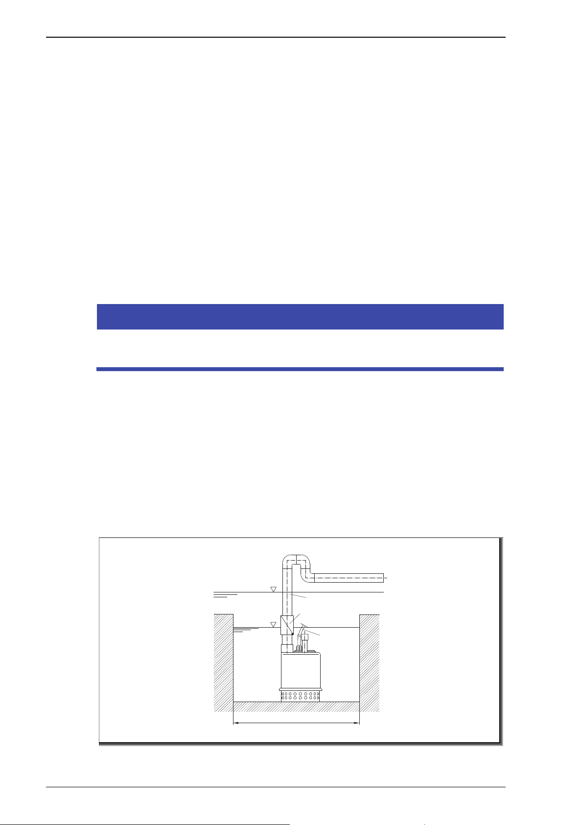
5.1.1 Montage im Brunnen
Beim Absenken der Pumpe in einen Brunnen/Schacht darauf
achten, dass die Pumpe nicht in Schlamm eintaucht, sondern auf
Pos: 67 /Technische Dokumentation/Betriebsanleitung/Installation/Einbauort/TOP 71-300/Flexi bler Einbau @ 7\mod_1468303405286_6.docx @ 88124 @ 3 @ 1
5.1.2 Flexibler Einbau
Pos: 68 /Technische Dokumentation/Betriebsanleitung/Installation/Einbauort/TOP 71-300/Stationärer Einsatz mit automatischer Schwimmerschaltung @ 7\mod_1468303486897_6.docx @ 88142 @ 3 @ 1
5.1.3 Stationärer Einsatz mit automatischer Schwimmerschaltung
ein Podest gestellt wird.
Einen Schlauch mit geeignetem Anschlussstück anschließen und
darauf achten, dass der Schlauch nicht geknickt wird. Pumpe in
das Wasser eintauchen und den Netzstecker in die Steckdose
stecken.
HINWEIS
Es wird empfohlen, eine Rückschlagklappe in die Druckleitung
einzubauen.
1. Steigrohr oder Schlauch spannungsfrei anschließen und die
Pumpe eintauchen.
2. Das Schwimmerkabel muss seitlich genügend Bewegungsfreiheit haben, damit es nicht an Bauteilen oder Schachtwänden hängen bleibt.
3. Auf ausreichende Kabellänge (mindestens 10 cm) zwischen
Schwimmer und Schwimmerkabelbefestigung am Griff
achten.
4. Netzstecker in die Steckdose stecken.
Pos: 69 /Technische Dokumentation/Betriebsanleitung/Installation/Einbauort/TOP 71-300/D90. 04.262-P @ 7\mod_1468308611801_6.docx @ 88313 @ @ 1
TOP 71-80
Rückstauebene
Druckleitung
Rückschlagklappe
Netzstecker
min. 0,4 x 0,4 m
Pos: 70 /Technische Dokumentation/Allgemeine Module/Abbildung @ 1\mod_1430211005604_6.docx @ 29219 @ @ 1
D90.04.262-1-P
Abb. 2
18 DE 11|2016

Pos: 71 /Technische Dokumentation/Betriebsanleitung/Installation/Einbauort/ TOP 71-300/D90.04.265-P @ 8\mod_1473163075633_0.docx @ 95875 @ @ 1
Installation
TOP 90-300
ON
OFF
min. 500
D90.04.265-P
Pos: 72 /Technische Dokumentation/Allgemeine Module/Abbildung @ 1\mod_1430211005604_6.docx @ 29219 @ @ 1
Abb. 3
Pos: 73 /Technische Dokumentation/Betriebsanleitung/Installation/Rohrlei tungen/Rohrleitungen @ 0\mod_1427882317137_6.docx @ 27150 @ 2 @ 1
5.2 Rohrleitungen
Pos: 74 /Technische Dokumentation/Betriebsanleitung/Installation/Rohrlei tungen/Rohrleitungen dimensionieren TOP @ 6\mod_1458651909809_6.docx @ 78955 @ 3 @ 1
5.2.1 Rohrleitungen dimensionieren
Leitung mit Gewindeanschluss ist entsprechend dem
Druckstutzen oder größer vorzusehen.
Bei fester Installation, Leitungen aus Metall oder Kunststoff
verwenden.
Bei zeitweiliger Installation können Kunststoffschläuche
verwendet werden. Diese müssen dem Druck der Pumpe
Pos: 75 /Technische Dokumentation/Betriebsanleitung/Installation/Rohrlei tungen/Rohrleitungen verlegen TOP 71-300 @ 7\mod_1468309606035_6.docx @ 88416 @ 3 @ 1
5.2.2 Rohrleitungen verlegen
Druckleitung möglichst gerade halten.
Plötzliche Querschnitts- und Richtungsänderungen
standhalten.
vermeiden.
Rückschlagventil an Druckleitung montieren.
Pumpe nicht als Festpunkt für die Rohrleitung verwenden.
Vor der Montage die Bauteile reinigen und spannungsfrei mit
geeignetem Dichtungsmaterial an die Pumpe anschließen.
Pos: 76 /Technische Dokumentation/Allgemeine Module/#### Seitenumbruch #### @ 0\mod_1426069111812_0.docx @ 769 @ @ 1
11|2016 DE 19

Installation
Pos: 77 /Technische Dokumentation/Betriebsanleitung/Installation/Elektrischer Anschlu ss/Elektrischer Anschluss @ 7\mod_1472021948294_6.docx @ 94169 @ 2 @ 1
5.3 Elektrischer Anschluss
Pos: 78 /Technische Dokumentation/Betriebsanleitung/Installation/Elektrischer Anschlu ss/Warnung Stromschlaggefahr @ 7\mod_1472027138452_6.docx @ 94223 @ @ 1
WARNUNG
Stromschlaggefahr durch unsachgemäßen Anschluss!
Elektrische Anschlüsse und Verbindungen müssen immer
von autorisiertem Fachpersonal vorgenommen werden.
VDE- und EVU-Vorschriften des
Energieversorgungsunternehmens beachten.
Pumpen für Schwimmbecken und deren Schutzbereiche
gemäß DIN VDE 0100-702 installieren.
Pos: 79 /Technisc he Dokumen tation/Bet riebsanl eitung/In stallati on/Elektri scher Ans chluss/Tr ennvorri chtung zur Un terbrechu ng @ 7\mod_1472028985822_6.docx @ 94292 @ @ 1
Trennvorrichtung zur Unterbrechung der
Spannungsversorgung mit einer Kontaktöffnung von
Pos: 80 /Technische Dokumentation/Betriebsanleitung/Installation/Elektrischer Anschlu ss/Warnung Stromschlaggefahr; Drehstrom ohne Motorschutz @ 7\mod_1472038867887_6.docx @ 94418 @ @ 1
mindestens 3 mm pro Pol installieren.
WARNUNG
Stromschlaggefahr durch Spannung am Gehäuse!
Bei Pumpen mit Drehstrommotor ohne Motorschutz, muss
ein korrekt eingestellter Motorschutzschalter installiert
werden. Dabei die Werte auf dem Typenschild beachten.
Pos: 81 /Technische Dokumentation/Betriebsanleitung/Installation/Elektrischer Anschluss/Fehlerstromschutzeinrichtung @ 7\mod_1472029729200_6.docx @ 94310 @ @ 1
Stromkreis mit einer Fehlerstromschutzeinrichtung,
Pos: 82 /Technische Dokumentation/Betriebsanleitung/Installation/Elektrischer Anschlu ss/geeignete Leitungstypen @ 7\mod_1472030911381_6.docx @ 94364 @ @ 1
Nennfehlerstrom I
FN
Nur geeignete Leitungstypen entsprechend den regionalen
Vorschriften verwenden.
Pos: 83 /Technische Dokumentation/Betriebsanleitung/Installation/Elektrischer Anschlu ss/Mindestquerschnitt @ 7\mod_1472031364414_6.docx @ 94382 @ @ 1
Mindestquerschnitt der elektrischen Leitungen der
Motorleistung und der Leitungslänge anpassen.
Pos: 84 /Technische Dokumentation/Betriebsanleitung/Installation/Elektrischer Anschluss/Not-Aus-Schalter nach DIN EN 809 @ 7\mod_1472038434346_6.docx @ 94400 @ @ 1
Wenn sich gefährliche Situationen ergeben können, Not-Aus-
Schalter gemäß DIN EN 809 vorsehen. Entsprechend dieser
Norm muss das der Errichter/Betreiber entscheiden.
Pos: 85 /Technische Dokumentation/Allgemeine Module/#### Seitenumbruch #### @ 0\mod_1426069111812_0.docx @ 769 @ @ 1
≤ 30 mA, schützen.
20 DE 11|2016
Pos: 86 /Technische Dokumentation/Betriebsanleitung/Installation/Elektrisch er Anschluss/Schaltplan 3~ 400/230V 50Hz @ 1\mod_1429162542167_6.docx @ 28491 @ 3 @ 1
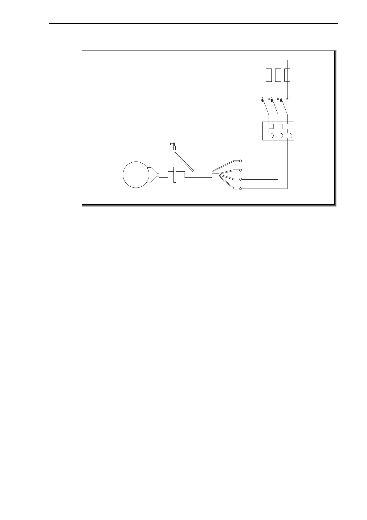
5.3.1 Schaltplan 3~ 400/230 V 50 Hz
Pos: 87 /Technische Dokumentation/Betriebsanleitung/Installation/Elektrisch er Anschluss/TOP/WG27.50.100-P @ 8\mod_1473154284022_0.docx @ 95746 @ @ 1
Installation
PEL1L2 L3
M
3~
Pos: 88 /Technische Dokumentation/Allgemeine Module/Abbildung @ 1\mod_1430211005604_6.docx @ 29219 @ @ 1
Abb. 4
Pos: 89 /Technische Dokumentation/Betriebsanleitung/Installation/Aufstellun g/ZIS 40/Montage/Demontage @ 3\mod_1444976154234_6.docx @ 48835 @ 2 @ 1
5.4 Montage/Demontage
Die Pumpe wird komplett montiert geliefert. Sollte die Pumpe
wegen Beschädigung oder ähnlichem demontiert werden, muss
Pos: 90 /Technische Dokumentation/Allgemeine Module/#### Seitenumbruch #### @ 0\mod_1426069111812_0.docx @ 769 @ @ 1
dies durch einen autorisierten Kundendienst erfolgen.
U
V
W
WG27.50.100-P
11|2016 DE 21

Inbetriebnahme/Außerbetriebnahme
Pos: 91 /Technische Dokumentation/Betriebsanleitung/Inbetriebnahme/ZIS 40/Inbetriebnahme/Auß erbetriebnahme @ 3\mod_1445236048158_6.docx @ 49295 @ 1 @ 1
6 Inbetriebnahme/Außerbetriebnahme
Pos: 92 /Technische Dokumentation/Betriebsanleitung/Inbetriebnahme/Inbetri ebnahme TOP 71-300 @ 7\mod_1468310056521_6.docx @ 88434 @ 2 @ 1
6.1 Inbetriebnahme
HINWEIS
Beschädigung der Pumpe/Anlage durch Trockenlauf!
Sicherstellen, dass die Pumpe/Anlage immer mit Wasser
gefüllt ist. Dies gilt auch bei der Drehrichtungskontrolle.
Die Pumpe sollte nur in eingetauchtem Zustand in Betrieb
genommen werden, um hohe Erwärmung des Motors zu
Vermeiden.
Um die Motorwärme gut abzuführen, sollten mindestens 2/3
der Pumpe überflutet sein. Ausnahme: kurzzeitiges
Leerpumpen.
Die Pumpe darf nicht gegen das geschlossene Absperrorgan
fördern, da sich das Fördermedium sonst erwärmt.
Pos: 93 /Technische Dokumentation/Betriebsanleitung/Inbetriebnahme/TOP/Pumpe einschalten TOP @ 6\mod_1458745539212_6.d ocx @ 79212 @ 2 @ 1
6.2 Pumpe einschalten
HINWEIS
Ein längerer Betrieb der Pumpe gegen einen geschlossenen
Schieber in der Druckleitung, kann zu Schäden durch Überhitzen
führen.
Pumpe zwei oder drei Mal starten, um den Zustand der
Anlage zu überprüfen.
Sicherstellen, dass die Geräusche, Vibrationen, Druckwerte
Pos: 94 /Technische Dokumentation/Betriebsanleitung/Inbetriebnahme/TOP/Ausführung mit Schwimmer TOP @ 6\mod_1458745731889_6.docx @ 79246 @ 3 @ 1
6.2.1 Ausführung mit Schwimmer
1. Stecker einstecken. Die Pumpe schaltet sich ein.
und elektrische Spannung normal sind.
2. Wenn der Mindest-Wasserstand „OFF“ erreicht ist, schaltet
sich die Pumpe automatisch ab. Dies wird von dem
Schwimmer geregelt.
3. Die Betriebsposition des Schwimmers ist werkseitig so
vorbereitet, dass bei der Position AUS ein MindestWasserstand gewährleistet ist.
Pos: 95 /Technische Dokumentation/Allgemeine Module/#### Seitenumbruch #### @ 0\mod_1426069111812_0.docx @ 769 @ @ 1
22 DE 11|2016

Inbetriebnahme/Außerbetriebnahme
Pos: 96 /Technische Dokumentation/Betriebsanleitung/Inbetriebnahme/TOP/Ausführung ohn e Schwimmer TOP @ 6\mod_1458745885883_6.docx @ 79263 @ 3 @ 1
6.2.2 Ausführung ohne Schwimmer
1. Stecker einstecken. Die Pumpe schaltet sich ein.
2. Wenn der Mindest-Wasserstand erreicht ist, die Stromzufuhr
unterbrechen und gegebenenfalls den Stecker aus der
Steckdose ziehen.
Pos: 97 /Technische Dokumentation/Betriebsanleitung/Inbetriebnahme/TOP/Kontrol le TOP @ 6\mod_1458745999357_6.docx @ 79280 @ 2 @ 1
6.3 Kontrolle
Nach der Installation muss die Länge des Schwimmerkabels
zum Wasserstand passend eingestellt werden.
Sicherstellen, dass die Pumpe die maximalen
Schaltvorgänge/Stunde nicht überschreitet.
Pos: 98 /Technische Dokumentation/Betriebsanleitung/Inbetriebnahme/TOP/Pumpe ausschalt en TOP @ 6\mod_1458745671132_6.docx @ 79229 @ 2 @ 1
6.4 Pumpe ausschalten
1. Schieber in der Druckleitung langsam schließen, um einen
Rückfluss zu verhindern.
Pos: 99 /Technische Dokumentation/Betriebsanleitung/Inbetriebnahme/TOP/Auß erbetriebnahme @ 6\mod_1458722257285_6.docx @ 79160 @ 2 @ 1
6.5 Außerbetriebnahme
1. Pumpe ausschalten, indem das elektrische Netz
unterbrochen wird.
2. Wenn nötig, Druckleitung demontieren.
3. Gegebenenfalls Schrauben von der Auflagefläche lösen.
4. Anschlusskabel in der Hand halten.
5. Pumpe am Haltgriff anheben. Je nach Gewicht eventuelle
2. Pumpe ausschalten.
Pos: 100 /Technische Dokumentation/Allgemeine Module/#### Seitenumbruch #### @ 0\mod_1426069111812_0.docx @ 769 @ @ 1
Hebemittel verwenden.
11|2016 DE 23

Störungen
Pos: 101 /Technische Dokumentation/Betriebsanleitung/Störung/Störungen @ 0\mod_1427964696943_6.docx @ 27356 @ 1 @ 1
7 Störungen
Pos: 102 /Technische Dokumentation/Betriebsanleitung/Störung/TOP 71-80/Motor läuft nicht @ 7\mod_1468248307116_6.d ocx @ 87953 @ @ 1
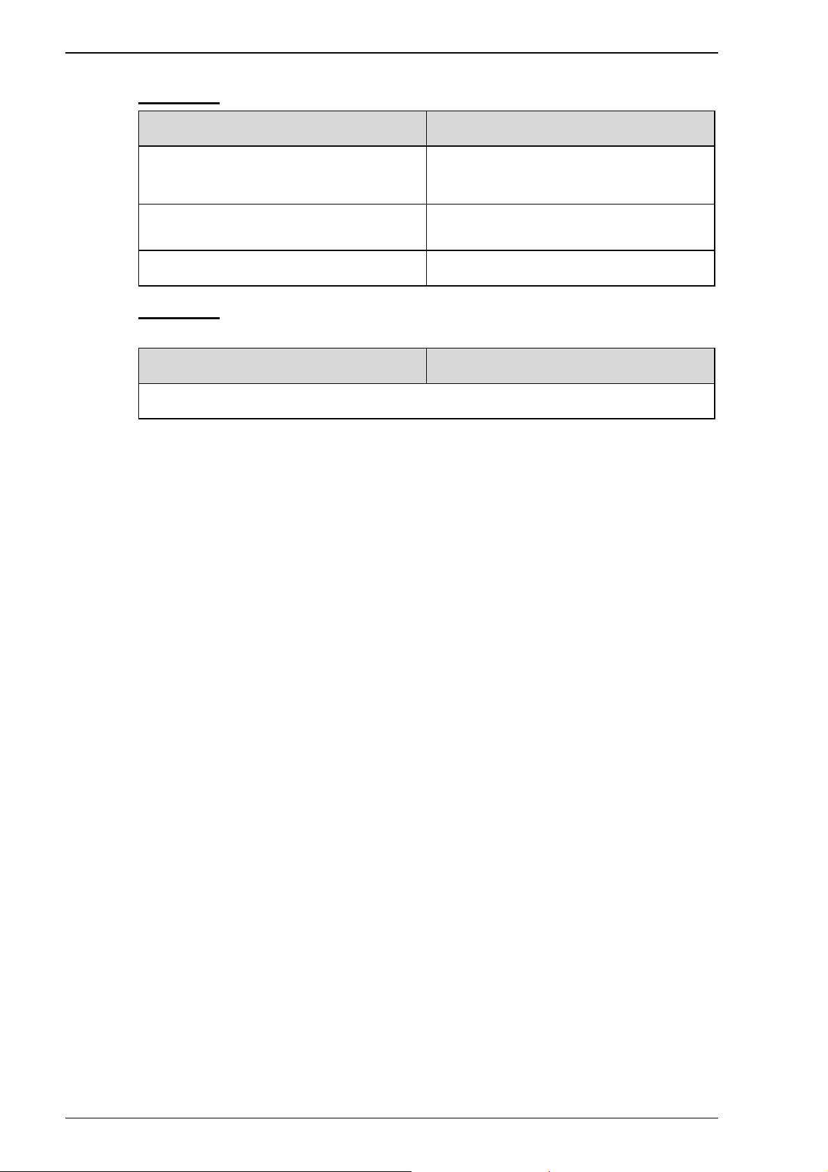
Störung: Motor läuft nicht
Mögliche Ursache Abhilfe
Netzstecker nicht
ordnungsgemäß eingesteckt.
Stromanschluss defekt. Durch Elektrofachkraft
Sicherungen durchgebrannt. Prüfen und eventuell
Motorschutz ausgelöst. Abwarten, bis
Stellung des Schwimmerschalters zu niedrig
Pos: 103 /Technische Dokumentation/Betriebsanleitung/Störung/TOP 71-80/Pumpe stoppt nach kurzem Betrieb @ 7\mod_1468248533623_6.docx @ 87970 @ @ 1
Störung: Pumpe stoppt nach kurzem Betrieb (Auslösen des
Thermoschutzschalters)
Mögliche Ursache Abhilfe
Prüfen und korrekt
einstellen.
prüfen lassen.
auswechseln.
Motorwicklung abgekühlt
ist und Motorschutz
wieder einschaltet.
Durch Anheben von Hand
ist eine Prüfung möglich.
Zu geringe
Spannungsversorgung.
Motorerwärmung durch zu
geringen Wasserstand im
Schacht.
Mediumtemperatur zu hoch. Wasser abkühlen lassen.
Pumpe durch
Verunreinigungen verstopft
oder mechanisch blockiert.
Pos: 104 /Technische Dokumentation/Allgemeine Module/#### Seitenumbruch #### @ 0\mod_1426069111812_0.docx @ 769 @ @ 1
Durch Elektrofachkraft
prüfen lassen.
Warten, bis der Motor
abgekühlt ist und
Wasserstand erhöhen.
Gehäuseteile und Laufrad
reinigen.
24 DE 11|2016

Pos: 105 /Technische Dokumentation/Betriebsanleitung/Störung/TOP 71-80/Pumpe läuft mit zu geringer Leistung @ 7\ mod_1468248705772_6.docx @ 87987 @ @ 1
Störung: Pumpe läuft mit zu geringer Leistung
Mögliche Ursache Abhilfe
Pumpe zieht Luft. Flüssigkeitsstand
Störungen
erhöhen.
Rohrleitungs- oder
Schlauchdurchmesser zu
gering.
Absperrorgan nicht voll
geöffnet.
Zu lange Rohr- oder
Schlauchleitung.
Förderhöhe zu hoch. Prüfen.
Pumpenteile oder Druckleitung
durch Verunreinigung teilweise
verstopft.
Laufrad und Saugplatte
verschlissen.
Pos: 106 /Technische Dokumentation/Betriebsanleitung/Störung/TOP 71-80/Keine Fördermenge, aber der Motor dr eht @ 7\mod_1468301270196_6.docx @ 88009 @ @ 1
Störung: Keine Fördermenge, aber der Motor dreht
Mögliche Ursache Abhilfe
Auf Nennweite des
Pumpenanschlusses
erhöhen.
Prüfen und Öffnen.
Verkürzen.
Prüfen und Reinigen.
Teile austauschen oder
Pumpe einsenden.
Zu große Förderhöhe. Prüfen.
Pumpenteile oder Leitung
verunreinigt.
Absperrorgan geschlossen. Prüfen und Öffnen.
Zu geringer Flüssigkeitsstand. Flüssigkeitsspiegel auf
Luftblase in der Pumpe (meist
bei Erstinbetriebnahme).
Pos: 107 /Technische Dokumentation/Allgemeine Module/#### Seitenumbruch #### @ 0\mod_1426069111812_0.docx @ 769 @ @ 1
Prüfen und Reinigen.
etwa 2/3 der Pumpenhöhe
vergrößern.
Flüssigkeitsspiegel auf
etwa Pumpenhöhe
vergrößern.
11|2016 DE 25
Störungen
Pos: 108 /Technische Dokumentation/Betriebsanleitung/Störung/TOP 71-80/Sicherungen lösen aus @ 7\mod_1468301548844_6.d ocx @ 88026 @ @ 1
Störung: Sicherungen lösen aus
Mögliche Ursache Abhilfe
Zu niedrig abgesichert. Gemäß Typenschild
absichern.
Pumpe durch
Verunreinigungen blockiert.
Motor defekt. An Fachbetrieb wenden.
Pos: 109 /Technische Dokumentation/Betriebsanleitung/Störung/TOP 71-80/Fehlerstromschutzschal ter oder andere Schutzmaßnahmen lösen aus @ 7\mod_1468301673671_6.docx @ 88043 @ @ 1
Störung: Fehlerstromschutzschalter oder andere
Schutzmaßnahmen lösen aus
Mögliche Ursache Abhilfe
Sofort an einen Fachbetrieb wenden!
Pos: 110 /Technische Dokumentation/Allgemeine Module/#### Seitenumbruch #### @ 0\mod_1426069111812_0.docx @ 769 @ @ 1
Prüfen und Reinigen.
26 DE 11|2016

Pos: 111 /Technische Dokumentation/Betriebsanleitung/Wartung/Instandhaltung/ TOP 71-300/Wartung/Instandhaltung TOP 71-300 @ 7\mod_1468302410720_6.docx @ 88060 @ 1 @ 1
8 Wartung/Instandhaltung
Die versenkbaren Pumpen sind weitestgehend wartungsfrei.
HINWEIS
Alle Arbeiten an der Pumpe nur in ausgeschaltetem Zustand
durchführen.
Wann? Was?
Regelmäßig Auslaufrohr reinigen.
Stromkabel kontrollieren.
Dichtungen kontrollieren,
gegebenenfalls ersetzen.
Saugsieb und Laufrad reinigen.
Wartung/Instandhaltung
Kondensatoren ersetzen.
Bei einem Defekt am Stromkabel ist der Kundendienst zu
kontaktieren.
Bei Betrieb der Pumpe in verschmutzten oder aggressiven
Medien ist es ratsam, die Pumpe sofort nach Gebrauch mit
reinem Wasser zu spülen. Ein Eintrocknen von
Schmutzrückständen oder ähnlichem kann zum Blockieren oder
Verschleiß führen.
WARNUNG
Abgetrennte Finger und Gliedmaßen durch Hineingreifen in die
Saugöffnung bei Betrieb der Pumpe (TOP 90-300).
Alle Arbeiten an der Pumpe nur bei Stillstand und mit
Schutzhandschuhen durchführen.
Pos: 112 /Technische Dokumentation/Betriebsanleitung/Wartung/Instandhaltung/TOP 71-300/Saugs ieb und Laufrad reinigen TOP 71-80 @ 7\mod_1468302711638_6.docx @ 88078 @ 2 @ 1
8.1 Saugsieb und Laufrad reinigen (TOP 71-80)
Falls das Saugsieb verstopft ist, muss dieses gereinigt
werden.
1. Pumpe vom Stromnetz trennen und aus dem Wasser
nehmen.
2. Saugsieb (143) entfernen.
3. Saugsieb (143) und Laufrad (230) reinigen.
4. Teile wieder montieren.
Pos: 113 /Technische Dokumentation/Betriebsanleitung/Wartung/Instandhaltung/ TOP 71-300/Laufrad reinigen TOP 90-300 @ 6\mod_1458746233203_6.docx @ 79297 @ 2 @ 1
11|2016 DE 27

Wartung/Instandhaltung
8.2 Laufrad reinigen (TOP 90-300)
Falls die Ansaugöffnung verstopft ist, muss diese gereinigt
werden. Dabei Schutzhandschuhe tragen.
1. Pumpe vom Stromnetz trennen und aus dem Wasser
nehmen.
2. Schrauben (900.5) lösen. Die Muttern sind an die Pumpe
geschweißt!
3. Den Pumpenkörper (101) herausziehen. Darauf achten, dass
der O-Ring nicht beschädigt wird.
4. Laufrad ist frei zugänglich. Laufrad reinigen. Raum zwischen
Laufrad und Gehäuse auf Verschmutzung kontrollieren.
Pos: 114 /Technische Dokumentation/Betriebsanleitung/Wartung/Instandhaltung/Zis matic/Überwinterungsvorschlag @ 3\mod_1442311129398_6.docx @ 46629 @ 2 @ 1
8.3 Überwinterungsvorschlag
5. Montage in umgekehrter Reihenfolge.
Für Pumpen im Freien, die während des Winters durch Frost
gefährdet sein können.
Rohrleitungen entleeren.
Die Pumpe sollte während der Frostperiode ausgebaut und
vertikal in einem trockenen Raum gelagert werden.
Pos: 115 /Technische Dokumentation/Betriebsanleitung/Wartung/Instandhaltung/ TOP 71-300/Ersatzteile TOP 71-80 @ 7\mod_1468244641352_6.docx @ 87881 @ 2 @ 1
8.4 Ersatzteile
Für Ersatzteilbestellungen sind folgende Angaben notwendig:
– Baureihe
– Teile - Benennung
– Positionsnummer
– Stückzahl
– Lieferadresse
– Versandart
Benennung und Positionsnummer kann der Explosionszeichnung
beziehungsweise Stückliste entnommen werden.
Pos: 116 /Technische Dokumentation/Betriebsanleitung/Wartung/Instandhaltung/ Gewährleistung @ 3\mod_1438613196089_6.docx @ 36830 @ 2 @ 1
8.5 Gewährleistung
Die Gewährleistung erstreckt sich auf die gelieferten Geräte mit
allen Teilen. Ausgenommen sind jedoch natürliche
Abnutzung/Verschleiß (DIN 3151/DIN-EN 13306) aller drehenden
beziehungsweise dynamisch beanspruchter Bauteile,
einschließlich spannungsbelasteter Elektronik-Komponenten.
Die Nichtbeachtung der Sicherheitshinweise kann zum Verlust
Pos: 117 /Technische Dokumentation/Betriebsanleitung/Wartung/Instandhaltung/ Serviceadressen @ 6\mod_1463648453826_6.docx @ 85297 @ 2 @ 1
28 DE 11|2016
jeglicher Schadensersatzansprüche führen.

8.6 Serviceadressen
Serviceadressen und Adressen von Kundendiensten sind auf der
Pos: 118 /Technische Dokumentation/Allgemeine Module/#### Seitenumbruch #### @ 0\mod_1426069111812_0.docx @ 769 @ @ 1
Internetseite www.speck-pumps.com zu finden.
Wartung/Instandhaltung
11|2016 DE 29

Entsorgung
Pos: 119 /Technische Dokumentation/Betriebsanleitung/Entsorgung/Entsorgung @ 1\mod_1428486567397_6.docx @ 27534 @ 1 @ 1
9 Entsorgung
Schädliche Fördermedien auffangen und vorschriftsgemäß
entsorgen.
Die Pumpe/Anlage beziehungsweise die Einzelteile müssen
nach Lebensdauerende fachgerecht entsorgt werden. Eine
Entsorgung im Hausmüll ist nicht zulässig!
Verpackungsmaterial, unter Beachtung der örtlichen
Pos: 120 /Technische Dokumentation/Allgemeine Module/#### Seitenumbruch #### @ 0\mod_1426069111812_0.docx @ 769 @ @ 1
Vorschriften, im Hausmüll entsorgen.
30 DE 11|2016

Technische Daten
Pos: 121 /Technische Dokumentation/Betriebsanleitung/Technische Daten/Technische Daten @ 2\mod_1436174888279_6.d ocx @ 34079 @ 1 @ 1
10 Technische Daten
Pos: 122 /Technische Dokumentation/Betriebsanleitung/Technische Daten/TOP 71 - TOP 300/Technische Daten TOP 71-300 @ 7\mod_1468245634208_6.docx @ 87935 @ @ 1
TD 50 Hz TOP 71 TOP 72 TOP 73 TOP 74
Rohranschluss [Rp] 1¼ 1½ 1½ 1½
max. Eintauchtiefe [m] 5 7 7 7
max.
Mediumtemperatur [°C]
max. Korngröße [mm] 10 10 10 10
Kabellänge [m] 10 10 10 10
1~ 230 V
P1 [kW] 0,51 0,90 1,30 1,70
P2 [kW] 0,25 0,55 0,75 1,10
I [A] 2,30 4,40 5,60 7,30
3~ 400 V
P1 [kW] 0,47 1,00 1,20 1,60
P2 [kW] 0,25 0,55 0,75 1,10
I [A] 0,80 2,00 2,40 3,00
Lwa [dB(A)] ≤ 70 ≤ 70 ≤ 70 ≤ 70
Gewicht [kg] 5,10 12,2 12,9 14,0
Schutzart [IP] 68 68 68 68
Wärmeschutzklasse
[ISO]
Drehzahl [min-1] 2850 2850 2850 2850
TD 50 Hz TOP 80 TOP 90 TOP 100 TOP 150
Rohranschluss [Rp] 1½ 2 2 2
max. Eintauchtiefe [m] 7 7 7 7
max.
Mediumtemperatur [°C]
max. Korngröße [mm] 10 50 50 50
Kabellänge [m] 10 10 10 10
1~ 230 V
P1 [kW] - 0,90(0,88)* 1,28(1,25)* 1,57(1,58)*
P2 [kW] - 0,55 0,75 1,10
I [A] - 3,90 5,80 7,30
3~ 400/230 V
P1 [kW] 1,70 0,85(0,80)* 1,19(1,18)* 1,55(1,57)*
P2 [kW] 1,50 0,55 0,75 1,10
I [A] 3,30 1,50(1,40)* 2,10 2,80
Lwa [dB(A)] ≤ 70 ≤ 70 ≤ 70 ≤ 70
Gewicht [kg] 13,5 16,2 18,2 20,2
Schutzart [IP] 68 68 68 68
Wärmeschutzklasse
[ISO]
Drehzahl [min-1] 2850 2850 2850 2850
50 35 35 35
F F F F
35 40 40 40
F F F F
11|2016 DE 31

Technische Daten
TD 50 Hz TOP 200 TOP 300
Rohranschluss [Rp] 2 2
max. Eintauchtiefe [m] 7 7
max.
40 40
Mediumtemperatur [°C]
max. Korngröße [mm] 50 50
Kabellänge [m] 10 10
1~ 230 V
P1 [kW] - P2 [kW] - I [A] - 3~ 400 V
P1 [kW] 2,08(1,92)* 2,90(2,40)*
P2 [kW] 1,50 2,20
I [A] 3,60(3,30)* 5,00(4,40)*
Lwa [dB(A)] ≤ 70 ≤ 70
Gewicht [kg] 20,0 26,0
Schutzart [IP] 68 68
Wärmeschutzklasse
F F
[ISO]
Drehzahl [min-1] 2850 2850
* Angaben in Klammern für Ausführung VOX (Vortex-Laufrad).
Pos: 123 /Technische Dokumentation/Allgemeine Module/#### Seitenumbruch #### @ 0\mod_1426069111812_0.docx @ 769 @ @ 1
32 DE 11|2016

Pos: 124 /Technische Dokumentation/Betriebsanleitung/Technische Daten/Maßzeichnung @ 3\mod_1439965097337_6.docx @ 40118 @ 2 @ 1
10.1 Maßzeichnung
Pos: 125 /Technische Dokumentation/Betriebsanleitung/Technische Daten/TOP 71 - TOP 300/D90.04.259-P @ 7\mod_1468308793300_0.d ocx @ 88330 @ @ 1
TOP 71-80
Technische Daten
G
E
D
Pos: 126 /Technische Dokumentation/Allgemeine Module/Abbildung @ 1\mod_1430211005604_6.docx @ 29219 @ @ 1
Abb. 5
Pos: 127 /Technische Dokumentation/Betriebsanleitung/Technische Daten/TOP 71 - TOP 300/Abmessungen Maßzeichnung TOP 71-80 @ 7\mod_1468241569547_6.d ocx @ 87779 @ @ 1
Typ Abmessungen [mm] Gewicht [kg]
D E F LMS G W/D WS
TOP 71 231 273 167 10 Rp 1 ¼ 4,4 4,6
LMS
F
D90.04.259-P
TOP 72 315 352 210 25 Rp 1 ½ 12,0 12,0
TOP 73 315 352 210 25 Rp 1 ½ 12,7 12,7
TOP 74 340 377 210 25 Rp 1 ½ 13,8 13,8
TOP 80 340 377 210 25 Rp 1 ½ 14,5 -
Pos: 128 /Technische Dokumentation/Allgemeine Module/#### Seitenumbruch #### @ 0\mod_1426069111812_0.docx @ 769 @ @ 1
11|2016 DE 33

Technische Daten
Pos: 129 /Technische Dokumentation/Betriebsanleitung/Technische Daten/TOP 71 - TOP 300/D90.04.266-P @ 8\mod_1473170170647_0.d ocx @ 95909 @ @ 1
TOP 90-300
H
133
Pos: 130 /Technische Dokumentation/Allgemeine Module/Abbildung @ 1\mod_1430211005604_6.docx @ 29219 @ @ 1
Abb. 6
Pos: 131 /Technische Dokumentation/Betriebsanleitung/Technische Daten/TOP 71 - TOP 300/Abmessungen Maßzeichnung TOP 90-300 @ 8\mod_1473170361731_6.docx @ 95926 @ @ 1
Typ Abmessungen [mm]
H (1~) H (3~)
TOP 90 485 485
TOP 100 515 485
98
50
Ø50
Ø190
228
Rp2
D90.04.266-P
TOP 150 515 515
TOP 200 - 515
TOP 300 - 545
Pos: 132 /Technische Dokumentation/Allgemeine Module/#### Seitenumbruch #### @ 0\mod_1426069111812_0.docx @ 769 @ @ 1
34 DE 11|2016

Pos: 133 /Technische Dokumentation/Betriebsanleitung/Technische Daten/Kennlinie @ 3\mod_1439965130186_6.docx @ 40133 @ 2 @ 1
10.2 Kennlinie
Pos: 134 /Technische Dokumentation/Betriebsanleitung/Technische Daten/TOP 71 - TOP 300/KL90.04.244-P @ 7\mod_1468308885424_0.d ocx @ 88347 @ @ 1
TOP 71-80
H [m]
25
20
15
10
Technische Daten
5
0
Pos: 135 /Technische Dokumentation/Allgemeine Module/Abbildung @ 1\mod_1430211005604_6.docx @ 29219 @ @ 1
Abb. 7
Pos: 136 /Technische Dokumentation/Betriebsanleitung/Technische Daten/TOP 71 - TOP 300/WG64.023.004-P @ 8\mod_1473159387306_0.docx @ 95824 @ @ 1
TOP 90-300
H [m]
25
20
15
TOP 300
TOP 200
TOP 150
TOP 71
10 20
TOP 72
TOP 73
TOP 80
TOP 74
30
Q [m³/h]
5004003002001000 50 150 250 350 450 Q [l/min]
KL90.04.244-P
TOP 100
TOP 90
10
5
0
0 10 20 30 40 50 Q [m³/h]
3002001000 400 500 600 700 800 900 Q [l/min]
Pos: 137 /Technische Dokumentation/Allgemeine Module/Abbildung @ 1\mod_1430211005604_6.docx @ 29219 @ @ 1
WG64.023.004-P
Abb. 8
11|2016 DE 35

Technische Daten
Pos: 138 /Technische Dokumentation/Betriebsanleitung/Technische Daten/TOP 71 - TOP 300/WG64.023.003-P @ 8\mod_1473159337405_0.docx @ 95807 @ @ 1
TOP 90-300 VOX
H [m]
20
TOP 300 VOX
15
TOP 200 VOX
TOP 150 VOX
10
TOP 100 VOX
TOP 90 VOX
5
0
Pos: 139 /Technische Dokumentation/Allgemeine Module/Abbildung @ 1\mod_1430211005604_6.docx @ 29219 @ @ 1
010
0 100 200
20
300 400 500
Abb. 9
Pos: 140 /Technische Dokumentation/Allgemeine Module/#### Seitenumbruch #### @ 0\mod_1426069111812_0.docx @ 769 @ @ 1
30 40 50
600 700 800 900
Q [m³/h]
Q [l/min]
WG64.023.003-P
36 DE 11|2016

Pos: 141 /Technische Dokumentation/Betriebsanleitung/Technische Daten/Explosionszeich nung @ 5\mod_1449758046184_6.docx @ 58625 @ 2 @ 1
10.3 Explosionszeichnung
Pos: 142 /Technische Dokumentation/Betriebsanleitung/Technische Daten/TOP 71 - TOP 300/D90.04.260-P @ 7\mod_1468308957532_0.d ocx @ 88364 @ @ 1
TOP 71
Technische Daten
552
321.2
819
321.1
412.2
524
350.1
412.4
421
433
826.2
900.2
412.6
824.1
824
576
101
412.7
826.1
161
900.2
230
412.1
504
922
162
900.2
143
412.6
900.2
554
525
900.2
812
833.1
837
833.2
900.2
350.2
412.5
811
Pos: 143 /Technische Dokumentation/Allgemeine Module/Abbildung @ 1\mod_1430211005604_6.docx @ 29219 @ @ 1
Abb. 10
Pos: 144 /Technische Dokumentation/Allgemeine Module/#### Seitenumbruch #### @ 0\mod_1426069111812_0.docx @ 769 @ @ 1
11|2016 DE 37

Technische Daten
Pos: 145 /Technische Dokumentation/Betriebsanleitung/Technische Daten/TOP 71 - TOP 300/Ersatzteilli ste TOP 71 @ 7\mod_1468242193596_6.docx @ 87796 @ @ 1
Ersatzteilliste TOP 71
Pos. Nr. Stück Bezeichnung
101 1 Pumpengehäuse
143 1 Saugsieb
162 1 Saugdeckel
230 1 Laufrad
321.1 1 A-seitiges Kugellager
321.2 1 B-seitiges Kugellager
350.1 1 Lagergehäuse A-seitig
350.2 1 Lagergehäuse B-seitig
412.1 1 O-Ring für Motorflansch
412.2 1 O-Ring für Wellenschutzhülse
412.4 1 O-Ring für Lagergehäuse unten
412.5 1 O-Ring für Lagergehäuse oben
412.6 2 O-Ring für Schrauben
412.7 2 O-Ring für Motorgehäuse/-deckel
421 1 Radialwellendichtring
433 1 Gleitringdichtung komplett
504 1 Abstandsring
524 1 Wellenschutzhülse
525 2 Abstandshülse
552 1 Spannscheibe
554 2 Beilagscheibe
576 1 Griff
811 1 Stator mit Motorgehäuse
812 1 Motorgehäusedeckel
819 1 Welle mit Rotor
824 1 Anschlusskabel
824.1 1 Schwimmkippschalter
826.1 1 Kabelstopfbuchse für Anschlusskabel
826.2 1 Kabelstopfbuchse für Schwimmkippschalter
833.1 1 Klemmkastendeckel
833.2 1 Klemmkasten
837 1 Kondensator
900.2 10 Zylinderkopfschraube
Pos: 146 /Technische Dokumentation/Allgemeine Module/#### Seitenumbruch #### @ 0\mod_1426069111812_0.docx @ 769 @ @ 1
922 1 Laufradmutter
38 DE 11|2016

Pos: 147 /Technische Dokumentation/Betriebsanleitung/Technische Daten/TOP 71 - TOP 300/D90.04.261-P @ 7\mod_1468308995654_0.d ocx @ 88381 @ @ 1
TOP 72-80
504.2
321.2
819
Technische Daten
824.1
824
321.1
504.1
812.1
433
412.4
839
412.1
412.6
900.3
551
230
162
922
940
900.2
900.3
412.6
826.2
900.4
101
412.7
826.1
812
833.1
837
836
833.2
554
920
554
525
412.3
811
905
Pos: 148 /Technische Dokumentation/Allgemeine Module/#### Seitenumbruch #### @ 0\mod_1426069111812_0.docx @ 769 @ @ 1
900.1
D90.04.261-P
11|2016 DE 39

Technische Daten
Pos: 149 /Technische Dokumentation/Betriebsanleitung/Technische Daten/TOP 71 - TOP 300/Ersatzteilli ste TOP 72 - TOP 80 @ 7\mod_1468243050631_6.docx @ 87813 @ @ 1
Ersatzteilliste TOP 72-TOP 80
Pos. Nr. Stück Bezeichnung
101 1 Pumpengehäuse
143 1 Saugsieb
162 1 Saugdeckel
230 1 Laufrad
321.1 1 A-seitiges Kugellager
321.2 1 B-seitiges Kugellager
412.1 1 O-Ring für Pumpengehäuse
412.3 1 O-Ring für Motorgehäuse
412.4 1 O-Ring für Lagergehäuse
412.6 3 O-Ring für Zylinderkopfschraube
412.7 1 O-Ring für Motorgehäusedeckel
433 1 Gleitringdichtung komplett
504.1 1 Abstandsring
504.2 1 Abstandsring
525 3 Abstandshülse
551 1 Abstandsscheibe
554 6 Beilagscheibe
811 1 Stator mit Motorgehäuse
812 1 Motorgehäusedeckel
812.1 1 Lagergehäuse
819 1 Welle mit Rotor
824 1 Anschlusskabel
824.1 1 Schwimmkippschalter
826.1 1 Kabelstopfbuchse für Anschlusskabel
826.2 1 Kabelstopfbuchse für Schwimmkippschalter
833.1 1 Klemmkastendeckel
833.2 1 Klemmkasten
836 1 Klemmenleiste
837 1 Kondensator
839 1 Motorflansch
900.1 3 Linsenkopfschraube
900.2 3 Zylinderkopfschraube
900.3 3 Linsenkopfschraube
900.4 2 Senkkopfschraube
905 3 Verbindungsstange
920 3 Mutter
922 1 Laufradmutter
940 1 Passfeder
Verschleißteile-Set, bestehend aus:
1x 321.1, 321.2, 412.1, 412.3, 412.4, 412.7, 433,
Pos: 150 /Technische Dokumentation/Allgemeine Module/#### Seitenumbruch #### @ 0\mod_1426069111812_0.docx @ 769 @ @ 1
504.1, 504.2, 551, 940, 3x 412.6
40 DE 11|2016

Pos: 151 /Technische Dokumentation/Betriebsanleitung/Technische Daten/TOP 71 - TOP 300/WG64.023.005-P @ 8\mod_1475676750388_0.docx @ 99283 @ @ 1
TOP 90-300
Technische Daten
826.2
900.3
412.6
824.1
837
838
833.2
400
576.1
576.2
824
812
836
826.1
412.1
230
554
900.6
839
412.6
900.3
551
932
811
900.5
412.3
504.1
412.4
504.2
321.2
819
321.1
812.1
433
525
940
162
502
101
230
554
900.6
162
101
932
Pos: 152 /Technische Dokumentation/Allgemeine Module/Abbildung @ 1\mod_1430211005604_6.docx @ 29219 @ @ 1
WG64.023.005-P
Abb. 11
Pos: 153 /Technische Dokumentation/Allgemeine Module/#### Seitenumbruch #### @ 0\mod_1426069111812_0.docx @ 769 @ @ 1
11|2016 DE 41

Technische Daten
Pos: 154 /Technische Dokumentation/Betriebsanleitung/Technische Daten/TOP 71 - TOP 300/Ersatzteilli ste TOP 90 - 300 @ 8\mod_1473159532431_6.docx @ 95841 @ @ 1
Ersatzteilliste TOP 90 - 300
Pos. Nr. Stück Bezeichnung
101 1 Pumpengehäuse
162 1 Saugdeckel
230 1 Laufrad
321.1 1 A-seitiges Kugellager
321.2 1 B-seitiges Kugellager
400 1 Flachdichtung
412.1 1 O-Ring
412.3 1 O-Ring
412.4 1 O-Ring
412.6 1 O-Ring
433 1 Gleitringdichtung komplett
502 1 Abstandsring (nur TOP 300/300 VOX)
504.1 1 Abstandsring (nur TOP 300/300 VOX)
504.2 1 Abstandsring
525 4 Abstandshülse
551 1 Abstandsscheibe
554 1 Beilagscheibe
576.1 1 Griff
576.2 1 Halterung für Schwimmkippschalter
811 1 Stator mit Motorgehäuse
812 1 Motorgehäusedeckel
812.1 1 Motorgehäusedeckel
819 1 Welle mit Rotor
824 1 Anschlusskabel mit Stecker
824.1 1 Schwimmkippschalter
826.1 1 Kabelstopfbuchse für Anschlusskabel
826.2 1 Kabelstopfbuchse für
Schwimmkippschalter
833.2 1 Klemmkasten
836 1 Klemmenleiste
837 1 Kondensator
838 1 Überlastschutz
839 1 Motorflansch
900.3 3 Zylinderkopfschraube
900.5 6 Zylinderkopfschraube
900.6 1 Zylinderkopfschraube
932 1 Sicherungsring
=== Ende der Liste für Textmarke Inhalt ===
940 1 Passfeder
42 DE 11|2016

Pos: 156 /Technische Dokumentation/Allgemeine Module/Index @ 2\mod_1435751775796_6.docx @ 33848 @ 1 @ 1
11 Index
=== Ende der Liste für Textmarke Index ===
Index
A
Außerbetriebnahme 23
B
Bestimmungsgemäße Verwendung 8
E
Elektrischer Anschluss 21
Entsorgung 31
Ersatzteile 10
F
Fehlanwendungen 8
Frost 12, 29
G
Gewährleistung 29
I
Inbetriebnahme 23
S
Störungen 11, 25
T
Transport 17
11|2016 DE 43


EN
EN Translation of original operation manual
Pos: 2 /Technische Dokumentation/Betriebsanleitung/_Titelbilder/D90.04.263-P @ 7\mod_1468308380442_0.docx @ 88266 @ @ 1
TOP 71 - TOP 300
=== Ende der Liste für Textmarke Titelblatt ===
D90.04.263-P
Pos: 4 /Technische Dokumentation/Al lgemeine Module/CE-Zeichen @ 2\mod_1434542175809_0.docx @ 33220 @ @ 1
=== Ende der Liste für Textmarke CE Zeichen ===

Pos: 7 /Technische Dokumentation/Allgemeine Module/Firmenadresse SPECK @ 3\mod_1439292393224_370.docx @ 37642 @ @ 1
Hauptstraße 3
91233 Neunkirchen am Sand, Germany
Phone +49 9123 949-0
Fax +49 9123 949-260
info@speck-pumps.com
www.speck-pumps.com
=== Ende der Liste für Textmar ke Firmenad resse ===
Pos: 9 /Technische Dokumentation/Allgemeine Module/Copyright @ 0\mod_1426071027221_370.docx @ 986 @ @ 1
All rights reserved.
Contents may not be distributed, duplicated, edited or
transferred to third parties without the written
permission of SPECK Pumpen Verkaufsgesellschaft
GmbH.
This document and all attached documents are not
subject to update service!
Subject to technical modifications!
=== Ende der Liste für Textmarke Copyright ===
2 EN 11|2016

Table of contents
Pos: 11 /Technische Dokumentation/Allgemeine Module/Inhaltsverzeichnis @ 2\mod_1435582896243_370.docx @ 33764 @ @ 1
=== Ende der Liste für Textmarke Ihvz ===
Table of contents
1 About this document .................................................................... 5
1.1 Using this manual ...................................................................... 5
1.2 Target group.............................................................................. 5
1.2.1 Symbols and means of representation .................................. 5
2 Safety ............................................................................................. 7
2.1 Intended use ............................................................................. 7
2.1.1 Possible misuse .................................................................... 7
2.2 Personnel qualification .............................................................. 7
2.3 Safety regulations ..................................................................... 8
2.4 Protective equipment ................................................................ 8
2.5 Structural modifications and spare parts ................................... 8
2.6 Signs ......................................................................................... 8
2.7 Residual risk.............................................................................. 9
2.7.1 Falling parts ........................................................................... 9
2.7.2 Rotating parts ........................................................................ 9
2.7.3 Electrical energy .................................................................... 9
2.7.4 Hot surfaces .......................................................................... 9
2.7.5 Hazardous materials ........................................................... 10
2.7.6 Suction danger .................................................................... 10
2.8 Faults ...................................................................................... 10
2.9 Preventing material damage ................................................... 10
2.9.1 Leakage and pipe breakage ................................................ 10
2.9.2 Dry running .......................................................................... 10
2.9.3 Overheating ......................................................................... 10
2.9.4 Blockages in the pump ........................................................ 11
2.9.5 Risk of frost ......................................................................... 11
2.9.6 Water temperature .............................................................. 11
2.9.7 Safe use of the product ....................................................... 11
3 Description .................................................................................. 13
3.1 Design ..................................................................................... 13
3.2 Material ................................................................................... 14
4 Transport and intermediate storage .......................................... 16
4.1 Transport ................................................................................. 16
4.2 Lifting the pump ....................................................................... 16
11|2016 EN 3

Table of contents
4.3 Storage ................................................................................... 17
4.4 Returns ................................................................................... 17
5 Installation ................................................................................... 18
5.1 Installation ............................................................................... 18
5.1.1 Installation in wells .............................................................. 18
5.1.2 Flexible installation .............................................................. 18
5.1.3 Fixed installation with automatic float switch ....................... 18
5.2 Pipes ....................................................................................... 19
5.2.1 Dimensioning pipework ....................................................... 19
5.2.2 Laying pipework .................................................................. 19
5.3 Electrical connection ............................................................... 20
5.3.1 Wiring diagram 3-phase 400/230V 50 Hz ............................ 21
5.4 Assembly/disassembly ............................................................ 21
6 Start-up/shut down ..................................................................... 22
6.1 Start-up ................................................................................... 22
6.2 Switching the pump on ............................................................ 22
6.2.1 Design with float switch ....................................................... 22
6.2.2 Design without float switch .................................................. 23
6.3 Control .................................................................................... 23
6.4 Turn the pump off .................................................................... 23
6.5 Decommissioning .................................................................... 23
7 Faults ........................................................................................... 24
8 Maintenance ................................................................................ 27
8.1 Clean the strainer basket and impeller (TOP 71-80) ............... 27
8.2 Clean the impeller (TOP 90-300) ............................................. 27
8.3 Suggestion for winter conditions .............................................. 28
8.4 Spare parts.............................................................................. 28
8.5 Warranty ................................................................................. 28
8.6 Service addresses ................................................................... 28
9 Disposal ....................................................................................... 29
10 Technical data ............................................................................. 30
10.1 Dimensional drawing ............................................................... 32
10.2 Characteristics ........................................................................ 34
10.3 Exploded drawing .................................................................... 36
11 Index ............................................................................................ 42
4 EN 11|2016

Pos: 13 /Technische Dokumentation/Betriebsanleitung/Zu diesem Dokument/Zu diesem Dokument @ 0\mod_1427210330941_370.docx @ 26356 @ 1 @ 1
1 About this document
Pos: 14 /Technische Dokumentation/Betriebsanleitung/Zu diesem Dokument/Umgang mit dieser Anleitung @ 0\mod_1427286785560_370. docx @ 26453 @ 2 @ 1
1.1 Using this manual
This manual is a component of the pump/unit. The pump/unit was
manufactured and tested according to the generally accepted
rules of technology. However, if the pump/unit is used incorrectly,
not serviced enough or tampered with, danger to life and limb or
material damage could result.
Read the manual carefully before use.
Keep the manual during the service life of the product.
Provide access to the manual for operating and service
personnel at all times.
Pass the manual on to any future owners or operators of the
Pos: 15 /Technische Dokumentation/Betriebsanleitung/Zu diesem Dokument/Zielgruppe Fachpersonal und Endverbraucher @ 6\mod_1463636324663_370.docx @ 84933 @ 2 @ 1
product.
About this document
1.2 Target group
This instruction manual is aimed both at qualified specialists and
the end customer. Descriptions aimed only at qualified specialists
are indicated accordingly (qualified specialist). This indication
Pos: 16 /Technische Dokumentation/Betriebsanleitung/Zu diesem Dokument/Symbole und Darstellungsmittel @ 0\mod _1427295380352_370.docx @ 26487 @ 3 @ 1
1.2.1 Symbols and means of representation
applies to the whole point. All other points are universally valid.
Warnings are used in this manual to warn you of personal injury.
Always read and observe warnings.
DANGER
Danger for people.
Non-observance results in death or serious injury.
WARNING
Danger for people.
Non-observance can result in death or serious injury.
CAUTION
Danger for people.
Non-observance can result in light to moderate injury.
NOTICE
Notes to prevent material damage, for better understanding or to
optimise the workflow.
11|2016 EN 5

About this document
Important information and technical notes are specially marked to
explain correct operation.
Symbol Meaning
1.
2.
Pos: 17 /Technische Dokumentation/Allgemeine Module/#### Seitenumbruch #### @ 0\mod_1426069111812_0.docx @ 891 @ @ 1
Instructions for a one-step action.
Directions for a multi-step action.
Observe the order of the steps.
6 EN 11|2016

Pos: 18 /Technische Dokumentation/Betriebsanleitung/Sicherheit/Sicherheit @ 0\m od_1427704077019_370.docx @ 26502 @ 1 @ 1
2 Safety
Pos: 19.1 /Technische Dokumentation/Betriebsanleitung/Sicherheit/Bestimmungsg emäße Verwendung/Bestimmungsgemäße Verwendung @ 6\mod_1463668113840_370.docx @ 85400 @ 2 @ 1
2.1 Intended use
Pos: 19.2 /Technische Dokumentation/Betriebsanleitung/Sicherheit/Bestimmungsg emäße Verwendung/Verwendung TOP 71-80 @ 7\mod_1468238775150_370.docx @ 87703 @ @ 1
The pump is suitable for water handling, cellar drainage, rain
water collection shafts and swimming pools.
Clean, cloudy or lightly contaminated water should be handled.
When handling sandy or abrasive media, increased wear to the
impeller, suction lid and seals is to be expected. These parts are
not covered under warranty.
The pumps are not suitable for handling dirty water with sandy
sediments or long-fibre components, viscous media, sewage, pulp
or corrosive or aggressive liquids. Moreover flammable or
Pos: 19.3 /Technische Dokumentation/Betriebsanleitung/Sicherheit/Bestimmungsg emäße Verwendung/Beachtung folgender Informationen @ 6\mod_1463724074544_370.docx @ 85440 @ @ 1
generally dangerous liquids may not be used.
Safety
Pos: 19.4 /Technische Dokumentation/Betriebsanleitung/Sicherheit/Bestimmungsg emäße Verwendung/Anleitung @ 6\mod_1463726632629_370.docx @ 85491 @ @ 1
• This manual
Observing the following information is vital for intended use:
Pos: 19.5 /Technische Dokumentation/Betriebsanleitung/Sicherheit/Bestimmungsg emäße Verwendung/Einsatzgrenzen, Anleitung @ 6\mod_1463726950694_370.docx @ 85525 @ @ 1
The pump/unit may only be operated within the application limits,
as specified in this manual.
Pos: 19.6 /Technische Dokumentation/Betriebsanleitung/Sicherheit/Bestimmungsg emäße Verwendung/andere nicht bestimmungsgemäße Verwendung @ 6\mod_1463723365593_370.docx @ 85423 @ @ 1
Any other use or use exceeding this is not an intended use and
must first be authorized by the manufacturer/supplier.
Pos: 20 /Technische Dokumentation/Betriebsanleitung/Sicherheit/Bestimmungsgemäße Verwendung/ Mögliche Fehlanwendungen @ 0\mod_1427707678973_370.docx @ 26547 @ 3 @ 1
2.1.1 Possible misuse
• Installing the pump/unit with stress on the pipes.
• Using the pump/unit beyond the operating limits specified in
the pump data sheet, e.g. excessive system pressure.
• Opening and servicing of the pump/unit by unqualified
personnel.
Pos: 21 /Technische Dokumentation/Betriebsanleitung/Sicherheit/Personalqual ifikation/Personalqualifikation - Gerät @ 0\mod_1427713388376_370.docx @ 26562 @ 2 @ 1
2.2 Personnel qualification
This unit can be used by children aged 8 and over as well as by
persons with limited physical, sensory or mental capacity or by
people with a lack of experience or knowledge, provided that they
are supervised or have been instructed in the safe use of the unit
and understand the resulting dangers. Children may not play with
the unit. Cleaning and user maintenance may not be carried out
by children without supervision.
Ensure that the following work is only performed by trained
professionals with the following qualifications:
– For mechanical work, for example replacing ball bearings
or mechanical seals: qualified mechanics.
11|2016 EN 7

Safety
– For work on the electric system: electricians.
Ensure that the following requirements are fulfilled:
– Personnel who do not yet have the appropriate
qualifications must receive the required training before
being allowed to work on the system.
– The personnels' responsibilities, for example working on
the product, electric equipment or hydraulic systems, are
set based on their qualifications and the job description.
– The personnel have read this manual and understand the
necessary working steps.
Pos: 22 /Technische Dokumentation/Betriebsanleitung/Sicherheit/Sicherheitsvorschrif ten/Sicherheitsvorschriften - MLY-04 @ 3\mod_1439898996857_370.docx @ 39772 @ 2 @ 1
2.3 Safety regulations
The operator of the system is responsible for the adherence to all
relevant statutory regulations and guidelines.
Observe the following regulations when using the pump/unit:
– This manual
– Warning and information signs on the product
– The valid national regulations for accident prevention
– The internal occupational, operational and safety
regulations of the operator
Pos: 23 /Technische Dokumentation/Betriebsanleitung/Sicherheit/Schutzeinrichtungen/S chutzeinrichtungen HIT @ 8\mod_1475149026943_370.docx @ 99086 @ 2 @ 1
2.4 Protective equipment
Reaching into moving parts, e.g. coupling and/or impeller, can
cause serious injury.
Never operate the pump/unit without protective covers
(basket).
Pos: 24 /Technische Dokumentation/Betriebsanleitung/Sicherheit/Bauliche Veränderungen und Ersatzt eile/Bauliche Veränderungen und Ersatzteile @ 0\mod_1427720976717_370.docx @ 26609 @ 2 @ 1
2.5 Structural modifications and spare parts
Alterations or modifications can affect operational safety.
Never modify or alter the pump/unit without the
manufacturer's permission.
Only use original spare parts and accessories authorised by
the manufacturer.
Pos: 25 /Technische Dokumentation/Betriebsanleitung/Sicherheit/Schilder/Schild er @ 0\mod_1427722464221_370.docx @ 26624 @ 2 @ 1
2.6 Signs
Ensure that all the signs on the complete pump/unit remain
Pos: 26 /Technische Dokumentation/Allgemeine Module/#### Seitenumbruch #### @ 0\mod_1426069111812_0.docx @ 891 @ @ 1
8 EN 11|2016
legible.

Pos: 27 /Technische Dokumentation/Betriebsanleitung/Sicherheit/Restrisiken /Restrisiken @ 0\mod_1427723332615_370.docx @ 26639 @ 2 @ 1
2.7 Residual risk
Pos: 28 /Technische Dokumentation/Betriebsanleitung/Sicherheit/Restrisiken /Herabfallende Teile TOP @ 6\mod_1458650682706_370.docx @ 78837 @ 3 @ 1
2.7.1 Falling parts
Suspend the pump unit from the handle.
Only use hoisting and load-bearing equipment which is
suitable and technically sound.
Do not stand under suspended loads.
Never lift or transport the pump/unit using electrical
Pos: 29 /Technische Dokumentation/Betriebsanleitung/Sicherheit/Restrisiken /Rotierende Teile - GSA @ 1\mod_1429096331026_370.docx @ 27892 @ 3 @ 1
2.7.2 Rotating parts
There is a risk of shearing and crushing due to exposed rotating
parts.
Only perform servicing when the pump/unit is not in
connection cables.
operation.
Safety
Prior to servicing, ensure the pump/unit cannot be switched
back on.
Immediately after finishing servicing, reattach or reactivate all
protective equipment.
Pos: 30 /Technische Dokumentation/Betriebsanleitung/Sicherheit/Restrisiken /Elektrische Energie - Zismatic @ 3\mod_1442305192268_370.docx @ 46356 @ 3 @ 1
2.7.3 Electrical energy
There is an increased risk of electric shock when working on the
electrical system due to the humid environment.
Electrical protective earth conductors which were not installed
correctly can also result in electric shocks, for example oxidation
or cable breakage.
Observe VDE and utility company regulations.
Before working on the electrical system, take the following
measures:
– Disconnect system from the power supply.
– Attach a warning sign: “Do not switch on! The system is
being worked on.”
– Ensure that the system is free of voltage.
Check the electrical system regularly to ensure it is in proper
working condition.
Pos: 31 /Technische Dokumentation/Betriebsanleitung/Sicherheit/Restrisiken /Heiße Oberfläche Pumpe @ 3\mod_1440423336222_370.docx @ 40223 @ 3 @ 1
2.7.4 Hot surfaces
During operation the pump can become very hot. Therefore there
is a danger of being burned.
Do not touch the pump during operation.
Allow the pump/unit to cool down before servicing it.
11|2016 EN 9

Safety
Pos: 32 /Technische Dokumentation/Betriebsanleitung/Sicherheit/Restrisiken/G efahrstoffe - Zismatic @ 3\mod_1442305532371_370.docx @ 46371 @ 3 @ 1
2.7.5 Hazardous materials
Ensure that the pump does not come into contact with
hazardous liquids or environments.
Pos: 33 /Technische Dokumentation/Betriebsanleitung/Sicherheit/Restrisiken/Ansauggef ahr @ 0\mod_1427783303305_370.docx @ 26737 @ 3 @ 1
2.7.6 Suction danger
Ensure that the suction openings conform to current guidelines,
standards and instructions.
Pos: 34 /Technische Dokumentation/Betriebsanleitung/Sicherheit/Störungen/Störungen @ 0\mod_1427783778053_370.docx @ 26752 @ 2 @ 1
2.8 Faults
In case of a fault, immediately switch the pump off and
remove it from operation.
Pos: 35 /Technische Dokumentation/Betriebsanleitung/Sicherheit/Störungen/Festsitzend e Pumpe - MLY-04 @ 3\mod_1439899322153_370.docx @ 39804 @ @ 1
Seized pump
If a pump seizes, and is switched on several times repeatedly, the
motor can be damaged. Observe the following points:
Do not switch the pump/unit on repeatedly.
Clean pump.
Have all faults repaired immediately.
Pos: 37 /Technische Dokumentation/Betriebsanleitung/Sicherheit/Vermeidung von Schäden/Vermeidung von Sachs chäden @ 0\mod_1427787266105_370.docx @ 26782 @ 2 @ 1
2.9 Preventing material damage
Pos: 38 /Technische Dokumentation/Betriebsanleitung/Sicherheit/Vermeidung von Schäden/Undichtigkeit und Rohrleitungsbruch - Zismatic @ 3\mod_1442305675412_370.docx @ 46386 @ 3 @ 1
2.9.1 Leakage and pipe breakage
If the pipe forces are exceeded, leaks can occur at the screwed
connection or the pump itself.
Do not use the pump as a fixed point for the pipe line.
Connect pipes free of load and mount them elastically. Install
compensators if necessary.
If the pump leaks, the unit may not be operated and must be
Pos: 39 /Technische Dokumentation/Betriebsanleitung/Sicherheit/Vermeidung von Schäden/Trockenl auf - Zismatic @ 3\mod_1442305848565_370.docx @ 46401 @ 3 @ 1
T
disconnected from the mains power supply.
2.9.2 Dry running
Various components can be damaged within seconds due to dry
running.
Do not allow the pump to run dry.
Pos: 40 /Technische Dokumentation/Betriebsanleitung/Sicherheit/Vermeidung von Schäden/Überhi tzen TOP @ 6\mod_1458745357411_370.docx @ 79197 @ 3 @ 1
2.9.3 Overheating
The following factors can lead to the pump overheating:
• Insufficient cooling of the pump.
• Closed valve in the pressure line.
Do not let the pump run dry.
Do not operate the pump with closed valves.
Pos: 41 /Technische Dokumentation/Betriebsanleitung/Sicherheit/Vermeidung von Schäden/Blockieren der Pumpe - Zismatic @ 3\mod_1442305928870_370.docx @ 46416 @ 3 @ 1
10 EN 11|2016

2.9.4 Blockages in the pump
Dirt particles can clog and block the pump.
Safety
Pos: 42 /Technische Dokumentation/Betriebsanleitung/Sicherheit/Vermeidung von Schäden/Fros tgefahr @ 3\mod_1442306015773_370.docx @ 46431 @ 3 @ 1
2.9.5 Risk of frost
Drain the pump/unit and pipes at risk of freezing in plenty of
time.
Remove the pump/unit during periods of frost and store it in a
dry room.
Do not install the pump on the bottom of the well/cistern.
Pos: 43 /Technische Dokumentation/Betriebsanleitung/Sicherheit/Vermeidung von Schäden/W assertemperatur 35 °C @ 1\mod_1429098446026_370.docx @ 28002 @ 3 @ 1
2.9.6 Water temperature
The water temperature must not exceed 35 °C.
Pos: 45 /Technische Dokumentation/Betriebsanleitung/Sicherheit/Vermeidung von Schäden/Sichere Nut zung des Produktes Multi @ 4\mod_1449223729904_370.docx @ 54467 @ 3 @ 1
2.9.7 Safe use of the product
Safe use of the product is no longer guaranteed in the following
instances:
If the pipework is not in proper condition.
If the pump seizes.
If protective devices are damaged or missing, e.g. protection
against accidental contact.
If there is stress on the pump/unit or pipes during installation.
If the pump/unit is not installed correctly.
If there is a technical fault.
Pos: 46 /Technische Dokumentation/Betriebsanleitung/Sicherheit/D90.04.264-P @ 7\mod_1470293084041_0.d ocx @ 89177 @ @ 1
11|2016 EN 11

Safety
A B C
CHEMICALS
OFF
230V
H max. 333 min. 111
Q max. 333 min. 111
°C
0
D90.04.264-P
Pos: 47 /Technische Dokumentation/Allgemeine Module/Abbildung @ 1\mod_1430211005604_370.docx @ 29221 @ @ 1
Fig. 1
Pos: 48 /Technische Dokumentation/Allgemeine Module/#### Seitenumbruch #### @ 0\mod_1426069111812_0.docx @ 891 @ @ 1
12 EN 11|2016

Pos: 49 /Technische Dokumentation/Betriebsanleitung/Beschreibung/Beschreibung @ 0\mod_1427795115728_370. docx @ 26937 @ 1 @ 1
3 Description
Pos: 50 /Technische Dokumentation/Betriebsanleitung/Beschreibung/TOP 71-80/Ausführung TOP 71-300 @ 7\mod _1468245090552_370.docx @ 87903 @ 2 @ 1
3.1 Design
The TOP 71-80 are vertical, fully submersible pumps with a half
open impeller. The TOP 90-300 are vertical, fully submersible
pumps with a single-channel or vortex impeller (VOX version).
The pumps work according to the centrifugal pump principle. The
motor runs in maintenance-free rolling bearings. The TOP 90-300
(VOX) range with a three-phase 400 V current has a PTC
thermistor.
The pumps can be fixed or portable.
There are three various designs:
– Single phase (W)
– Single phase with float switch (WS)
Description
– Three-phase (D)
Single phase motor:
Every single phase motor has a thermal sensor which turns the
motor off if the winding is overloaded or overheated.
Once the winding has cooled down, the thermal sensor
automatically unblocks the motor.
Single phase motor with float switch:
The pump has an added float switch which turns the motor on/off
automatically.
Pos: 51 /Technische Dokumentation/Allgemeine Module/#### Seitenumbruch #### @ 0\mod_1426069111812_0.docx @ 891 @ @ 1
11|2016 EN 13

Description
Pos: 52 /Technische Dokumentation/Betriebsanleitung/Beschreibung/TOP 71-80/Werkstoffe @ 7\mod_1468245112521_370.docx @ 8792 1 @ 2 @ 1
3.2 Material
TOP 71
Pump/outer housing Stainless steel 1.4301
Impeller Stainless steel 1.4301
Suction grille Stainless steel 1.4301
Pump shaft Stainless steel 1.4305
Motor housing Stainless steel 1.4301
Shaft seal Mechanical seal SiC/SiC/Viton
Oil trap ESSO MARCOL 152, 40 ml
O-rings NBR
Cable (1 ~ phase) 3 x 0.75 mm²
Cable (3 ~ phase) 4 x 1 mm²
H07RN8-F with
shock-proof plug
H07RN-F without
plug
TOP 72-80
Pump/outer housing Stainless steel 1.4301
Impeller Stainless steel 1.4301
Suction grille Stainless steel 1.4301
Pump shaft Stainless steel 1.4305
Motor housing Stainless steel 1.4301
Shaft seal
Oil trap ESSO MARCOL 172, 180 ml
O-rings NBR
Cable (1 ~ phase)
Cable (3 ~ phase) 4 x 1 mm²
Mechanical seal SiC/SiC and
carbon/ceramic
3 x 1 mm²
(TOP 72)
H07RN8-F with
shock-proof plug
3 x 1.5 mm²
(TOP 73/74)
H07RN8-F
without plug
14 EN 11|2016

TOP 90-300
Pump/outer housing Stainless steel 1.4301
Impeller Stainless steel 1.4301
Pump shaft Stainless steel 1.4305
Motor housing Stainless steel 1.4301
Motor spacer ring
(TOP 300 (VOX))
Shaft seal
Oil trap ESSO MARCOL 152, 385 ml
O-rings NBR
Cable (1 ~ phase)
Pos: 53 /Technische Dokumentation/Allgemeine Module/#### Seitenumbruch #### @ 0\mod_1426069111812_0.docx @ 891 @ @ 1
Cable (3 ~ phase) 4 x 1.5 mm² FG50K
Cast iron GG
Mechanical seal Motor:
carbon/ceramic
Pump: SiC/SiC
3 x 1 mm²
(TOP 90)
H07RN-F with
shock-proof plug
3 x 1.5 mm²
(TOP 100-300)
Description
11|2016 EN 15

Transport and intermediate storage
Pos: 54 /Technische Dokumentation/Betriebsanleitung/Transport und Zwischenlagerung/Transport und Zwischen lagerung @ 0\mod_1427801635560_370.docx @ 27002 @ 1 @ 1
4 Transport and intermediate storage
Pos: 55 /Technische Dokumentation/Betriebsanleitung/Transport und Zwischenlagerung/Transport TOP @ 6\mod_1458651488898_370.docx @ 78888 @ 2 @ 1
4.1 Transport
Check the delivery condition.
– Check the packaging for transport damage.
– Identify the damages, document them with photographs
and contact the retailer.
Pos: 56 /Technische Dokumentation/Betriebsanleitung/Transport und Zwischenlagerung/Pumpe anheben TOP @ 6\mod_1458651567961_370.doc x @ 78905 @ 2 @ 1
4.2 Lifting the pump
DANGER
Goods being transported can fall and result in death or crushing of
limbs!
Suspend the pump unit from the handle.
Only use suitable and technically sound hoisting equipment
with sufficient load bearing capacity.
Do not stand under suspended loads.
Never lift or transport the pump/unit using electrical
connection cables.
Pos: 57 /Technische Dokumentation/Allgemeine Module/#### Seitenumbruch #### @ 0\mod_1426069111812_0.docx @ 891 @ @ 1
16 EN 11|2016

Pos: 58 /Technische Dokumentation/Betriebsanleitung/Transport und Zwischenlagerung/Lagerung @ 7\mod _1463988839544_370.docx @ 85895 @ 2 @ 1
4.3 Storage
Pos: 59 /Technische Dokumentation/Betriebsanleitung/Transport und Zwischenlagerung/Hinweis: Korrosion @ 7\mod_1463985238413_370.docx @ 85763 @ @ 1
NOTICE
Corrosion is possible due to storage in humid conditions with
fluctuating temperatures!
Condensation can corrode windings and metal parts.
Store the pump/unit in a dry environment at a temperature
which is as constant as possible.
Pos: 60 /Technische Dokumentation/Betriebsanleitung/Transport und Zwischenlagerung/Hinweis: Beschädigung des Gewindes @ 7\mod_1463985559638_370.docx @ 85781 @ @ 1
NOTICE
There is a risk of damage to the winding and entry of foreign
matter due to open ports!
Do not remove the port covers until the pipes are ready to be
connected.
Pos: 61 /Technische Dokumentation/Betriebsanleitung/Transport und Zwischenlagerung/Hinweis: Beschädigung oder Verlust von Einzelteilen @ 7\mod_1463986038711_370.docx @ 85799 @ @ 1
Transport and intermediate storage
NOTICE
Damage or loss of individual parts!
Do not open the original packaging until the installation or
keep individual parts in the original packaging until the
installation.
Pos: 62 /Technische Dokumentation/Betriebsanleitung/Transport und Zwischenlagerung/Rücksendung TOP @ 7\mod_1470118164002_370.docx @ 89123 @ 2 @ 1
4.4 Returns
– Drain the pump/unit completely.
– Rinse and clean the pump/unit with clear water.
– Pack the pump/unit in a box and send it to the specialist
Pos: 63 /Technische Dokumentation/Allgemeine Module/#### Seitenumbruch #### @ 0\mod_1426069111812_0.docx @ 891 @ @ 1
retailer or manufacturer.
11|2016 EN 17

Installation
Pos: 64 /Technische Dokumentation/Betriebsanleitung/Installation/Installation @ 0\m od_1427869040467_370.docx @ 27032 @ 1 @ 1
5 Installation
Pos: 65 /Technische Dokumentation/Betriebsanleitung/Installation/Einbauort/Einbau @ 6\mod_1458651885033_370.docx @ 78940 @ 2 @ 1
5.1 Installation
Pos: 66 /Technische Dokumentation/Betriebsanleitung/Installation/Einbauort/TOP 71-300/Montag e im Brunnen TOP 71-80 @ 7\mod_1468303211762_370.docx @ 88110 @ 3 @ 1
5.1.1 Installation in wells
When lowering the pump into a well/shaft, ensure that the pump
Pos: 67 /Technische Dokumentation/Betriebsanleitung/Installation/Einbauort/TOP 71-300/Flexi bler Einbau @ 7\mod_1468303405286_370.docx @ 88128 @ 3 @ 1
5.1.2 Flexible installation
Pos: 68 /Technische Dokumentation/Betriebsanleitung/Installation/Einbauort/TOP 71-300/Stationärer Einsatz mit automatischer Schwimmerschaltung @ 7\mod_1468303486897_370.docx @ 88146 @ 3 @ 1
5.1.3 Fixed installation with automatic float switch
doesn’t sink into the mud but is placed on a platform.
Attach a hose with a suitable connection piece and ensure that
the hose does not buckle. Submerge the pump in the water and
plug it into the mains.
NOTICE
We recommend installing a non-return valve in the pressure line.
1. Connect the rising pipe or hose free of tension and submerge
the pump in the water.
2. The cable for the float switch must have sufficient room for
movement in order to avoid it catching on components or the
shaft wall.
3. Ensure there is sufficient cable length (minimum 10 cm)
between the float switch and the float switch cable bracket on
the handle.
4. Plug into the mains.
Pos: 69 /Technische Dokumentation/Betriebsanleitung/Installation/Einbauort/TOP 71-300/D90. 04.262-P @ 7\mod_1468308611801_370.docx @ 88317 @ @ 1
TOP 71-80
Backflow level
Pressure line
Non-return valve
Mains plug
min. 0.4 x 0.4 m
Pos: 70 /Technische Dokumentation/Allgemeine Module/Abbildung @ 1\mod_1430211005604_370.docx @ 29221 @ @ 1
D90.04.262-2-P
Fig. 2
Pos: 71 /Technische Dokumentation/Betriebsanleitung/Installation/Einbauort/TOP 71-300/D90. 04.265-P @ 8\mod_1473163075633_0.docx @ 95879 @ @ 1
18 EN 11|2016

ON
Installation
TOP 90-300
OFF
min. 500
D90.04.265-P
Pos: 72 /Technische Dokumentation/Allgemeine Module/Abbildung @ 1\mod_1430211005604_370.docx @ 29221 @ @ 1
Fig. 3
Pos: 73 /Technische Dokumentation/Betriebsanleitung/Installation/Rohrlei tungen/Rohrleitungen @ 0\mod_1427882317137_370.docx @ 27152 @ 2 @ 1
5.2 Pipes
Pos: 74 /Technische Dokumentation/Betriebsanleitung/Installation/Rohrlei tungen/Rohrleitungen dimensionieren TOP @ 6\mod_1458651909809_370.docx @ 78957 @ 3 @ 1
5.2.1 Dimensioning pipework
The pipework with threaded connection must be provided
according to the discharge outlet or larger.
Use metal or plastic for pipework in fixed installations.
Plastic hoses may be used in temporary installations. These
Pos: 75 /Technische Dokumentation/Betriebsanleitung/Installation/Rohrlei tungen/Rohrleitungen verlegen TOP 71-300 @ 7\mod_1468309606035_370.docx @ 88420 @ 3 @ 1
5.2.2 Laying pipework
Keep the pressure lines as short and straight as possible.
Avoid sudden changes to the cross-section and direction.
Assemble a non-return valve in the pressure line.
must withstand the pressure of the pump.
Do not use the pump as a fixing point for the pipework.
Prior to assembly, clean the components and attach them to
the pump tension free using suitable sealing materials.
Pos: 76 /Technische Dokumentation/Allgemeine Module/#### Seitenumbruch #### @ 0\mod_1426069111812_0.docx @ 891 @ @ 1
11|2016 EN 19

Installation
Pos: 77 /Technische Dokumentation/Betriebsanleitung/Installation/Elektrischer Anschlu ss/Elektrischer Anschluss @ 7\mod_1472021948294_370.docx @ 94173 @ 2 @ 1
5.3 Electrical connection
Pos: 78 /Technische Dokumentation/Betriebsanleitung/Installation/Elektrischer Anschlu ss/Warnung Stromschlaggefahr @ 7\mod_1472027138452_370.docx @ 94227 @ @ 1
WARNING
Risk of electric shock due to incorrect connections!
Electrical connections must always be carried out by
authorised specialists.
Observe VDE and utility company regulations.
Install swimming pools and their protection according to
DIN VDE 0100-702.
Pos: 79 /Technische Dokumentation/Betriebsanleitung/Installation/Elektrischer Anschluss/Trennvorrichtung zur Unterbrechung @ 7\mod_1472028985822_370.docx @ 94296 @ @ 1
Install a disconnecting device with at least a 3 mm contact
Pos: 80 /Technische Dokumentation/Betriebsanleitung/Installation/Elektrischer Anschlu ss/Warnung Stromschlaggefahr; Drehstrom ohne Motorschutz @ 7\mod_1472038867887_370.docx @ 94422 @ @ 1
gap per pole to interrupt the power supply.
WARNING
Risk of electric shock due to voltage on the housing!
An overload switch which is set correctly must be installed for
pumps with three-phase motors without motor protection. In
doing so, observe the values on the motor name plate.
Pos: 81 /Technische Dokumentation/Betriebsanleitung/Installation/Elektrischer Anschluss/Fehlerstromschutzeinrichtung @ 7\mod_1472029729200_370.docx @ 94314 @ @ 1
Protect power supply with a ground fault circuit interrupter,
nominal residual current I
Pos: 82 /Technische Dokumentation/Betriebsanleitung/Installation/Elektrischer Anschlu ss/geeignete Leitungstypen @ 7\mod_1472030911381_370.docx @ 94368 @ @ 1
Only use suitable pipe types according to regional
regulations.
Pos: 83 /Technische Dokumentation/Betriebsanleitung/Installation/Elektrischer Anschlu ss/Mindestquerschnitt @ 7\mod_1472031364414_370.docx @ 94386 @ @ 1
Adjust minimum diameter of the electrical pipes to
accommodate the motor output and pipe length.
Pos: 84 /Technische Dokumentation/Betriebsanleitung/Installation/Elektrischer Anschluss/Not-Aus-Schalter nach DIN EN 809 @ 7\mod_1472038434346_370.docx @ 94404 @ @ 1
If hazardous situations can occur, provide emergency off
switch according to DIN EN 809. The builder/operator must
make a decision according to this standard.
Pos: 85 /Technische Dokumentation/Allgemeine Module/#### Seitenumbruch #### @ 0\mod_1426069111812_0.docx @ 891 @ @ 1
≤ 30 mA.
FN
20 EN 11|2016

Pos: 86 /Technische Dokumentation/Betriebsanleitung/Installation/Elektrisch er Anschluss/Schaltplan 3~ 400/230V 50Hz @ 1\mod_1429162542167_370.docx @ 28493 @ 3 @ 1
5.3.1 Wiring diagram 3-phase 400/230V 50 Hz
Pos: 87 /Technische Dokumentation/Betriebsanleitung/Installation/Elektrisch er Anschluss/TOP/WG27.50.100-P @ 8\mod_1473154284022_0.docx @ 95760 @ @ 1
Installation
PEL1L2 L3
M
3~
Pos: 88 /Technische Dokumentation/Allgemeine Module/Abbildung @ 1\mod_1430211005604_370.docx @ 29221 @ @ 1
Fig. 4
Pos: 89 /Technische Dokumentation/Betriebsanleitung/Installation/Aufstellun g/ZIS 40/Montage/Demontage @ 3\mod_1444976154234_370.docx @ 48837 @ 2 @ 1
5.4 Assembly/disassembly
The pump is delivered completely assembled. Should the pump
need to be disassembled due to damage or otherwise, this must
Pos: 90 /Technische Dokumentation/Allgemeine Module/#### Seitenumbruch #### @ 0\mod_1426069111812_0.docx @ 891 @ @ 1
be carried out by an authorised customer service representative.
U
V
W
WG27.50.100-P
11|2016 EN 21

Start-up/shut down
Pos: 91 /Technische Dokumentation/Betriebsanleitung/Inbetriebnahme/ZIS 40/Inbetriebnahme/Auß erbetriebnahme @ 3\mod_1445236048158_370.docx @ 49297 @ 1 @ 1
6 Start-up/shut down
Pos: 92 /Technische Dokumentation/Betriebsanleitung/Inbetriebnahme/Inbetri ebnahme TOP 71-300 @ 7\mod_1468310056521_370.docx @ 88438 @ 2 @ 1
6.1 Start-up
NOTICE
The pump/unit can be damaged if it runs dry!
Ensure that the pump/unit is always full of water. This also
applies to checking the rotation direction.
The pump should only be operated in a submerged state in
order to avoid the motor overheating.
Minimum 2/3 of the pump should be flooded in order to
discharge the heat from the motor. Exception: short-term
drainage.
The pump must not deliver against a closed shut-off valve as
this will cause the pumped media to heat up.
Pos: 93 /Technische Dokumentation/Betriebsanleitung/Inbetriebnahme/TOP/Pumpe einschalten TOP @ 6\mod_1458745539212_370.d ocx @ 79214 @ 2 @ 1
6.2 Switching the pump on
NOTICE
Operating the pump against a closed valve in the pressure line
over a longer period of time can lead to damage due to
overheating.
Start the pump two or three times in order to check the
condition of the unit.
Ensure that the noise, vibration, pressure values and
Pos: 94 /Technische Dokumentation/Betriebsanleitung/Inbetriebnahme/TOP/Ausführung mit Schwimmer TOP @ 6\mod_1458745731889_370.docx @ 79248 @ 3 @ 1
6.2.1 Design with float switch
1. Insert the plug. The pump will turn itself on.
electrical voltage are normal.
2. When the minimum water level has been reached, the pump
automatically turns itself off. This is controlled by the float
switch.
3. The operating position of the float switch is set in the factory
so that a minimum water level is guaranteed when in the
OFF position.
Pos: 95 /Technische Dokumentation/Allgemeine Module/#### Seitenumbruch #### @ 0\mod_1426069111812_0.docx @ 891 @ @ 1
22 EN 11|2016

Pos: 96 /Technische Dokumentation/Betriebsanleitung/Inbetriebnahme/TOP/Ausführung ohn e Schwimmer TOP @ 6\mod_1458745885883_370.docx @ 79265 @ 3 @ 1
6.2.2 Design without float switch
1. Insert the plug. The pump will turn itself on.
2. When the minimum water level has been reached,
disconnect the power supply and remove the plug if
necessary.
Pos: 97 /Technische Dokumentation/Betriebsanleitung/Inbetriebnahme/TOP/Kontrol le TOP @ 6\mod_1458745999357_370.docx @ 79282 @ 2 @ 1
6.3 Control
Following installation, the length of the float cable should be
adjusted to correspond to the water level.
Ensure that the pump does not exceed the maximum switch
procedure per hour.
Pos: 98 /Technische Dokumentation/Betriebsanleitung/Inbetriebnahme/TOP/Pumpe ausschalt en TOP @ 6\mod_1458745671132_370.docx @ 79231 @ 2 @ 1
6.4 Turn the pump off
1. Slowly close the valve in the pressure line in order to avoid a
backflow.
Start-up/shut down
Pos: 99 /Technische Dokumentation/Betriebsanleitung/Inbetriebnahme/TOP/Auß erbetriebnahme @ 6\mod_1458722257285_370.docx @ 79162 @ 2 @ 1
6.5 Decommissioning
1. Turn the pump off by disconnecting the power supply.
2. If necessary, disassemble the pressure line.
3. If necessary, release the screws from the contact area.
4. Take the connection cable in your hand.
5. Lift the pump using the handle. Depending on the weight, use
2. Turn the pump off.
Pos: 100 /Technische Dokumentation/Allgemeine Module/#### Seitenumbruch #### @ 0\mod_1426069111812_0.docx @ 891 @ @ 1
lifting equipment.
11|2016 EN 23

Faults
Pos: 101 /Technische Dokumentation/Betriebsanleitung/Störung/Störungen @ 0\mod_1427964696943_370.docx @ 27358 @ 1 @ 1
7 Faults
Pos: 102 /Technische Dokumentation/Betriebsanleitung/Störung/TOP 71-80/Motor läuft nicht @ 7\mod_1468248307116_370.d ocx @ 87957 @ @ 1
Fault: Pump doesn’t run
Possible cause Solution
Power supply not connected
properly.
Faulty power connection. Have a qualified
Burnt fuse. Check and replace if
Motor protection triggered. Wait for the motor winding
Float switch positioned too low. Check by lifting it by hand.
Pos: 103 /Technische Dokumentation/Betriebsanleitung/Störung/TOP 71-80/Pumpe stoppt nach kurzem Betrieb @ 7\mod_1468248533623_370.docx @ 87974 @ @ 1
Fault: Pump stops after a short operating time (heat protection
switch is triggered)
Possible cause Solution
Check the connection.
electrician check it.
necessary.
to cool down and the
motor protection to turn
back on.
Too low a power supply. Have a qualified
Motor overheating due to
insufficient water level in shaft.
Media temperature too high. Let the water cool down.
Pump blocked due to
contamination or blocked
mechanically.
Pos: 104 /Technische Dokumentation/Allgemeine Module/#### Seitenumbruch #### @ 0\mod_1426069111812_0.docx @ 891 @ @ 1
electrician check it.
Wait for the motor to cool
down and increase the
water level.
Clean housing parts and
impeller.
24 EN 11|2016

Pos: 105 /Technische Dokumentation/Betriebsanleitung/Störung/TOP 71-80/Pumpe läuft mit zu geringer Leistung @ 7\ mod_1468248705772_370.docx @ 87991 @ @ 1
Fault: Pump runs with too low a performance
Possible cause Solution
Pump drawing air in. Increase the liquid level.
Faults
Pipe or hose diameter too
small.
Shut-off valve not fully open.
Pipe or hose is too long.
Dynamic head is too high. Check it.
Pump parts or pressure line
partly blocked due to
contamination.
Impeller and suction plate
worn.
Pos: 106 /Technische Dokumentation/Betriebsanleitung/Störung/TOP 71-80/Keine Fördermenge, aber der Motor dr eht @ 7\mod_1468301270196_370.docx @ 88013 @ @ 1
Fault: No flow rate but the motor is turning
Possible cause Solution
Dynamic head is too large. Check it.
Pump parts or pipework dirty.
Increase it to the diameter
of the pump connection.
Check and open.
Shorten it.
Check and clean it.
Replace the parts or send
the pump in for servicing.
Check and clean.
Shut-off valve is closed.
Liquid level too low. Increase the liquid level to
Air bubble in the pump (mainly
during initial commissioning).
Pos: 107 /Technische Dokumentation/Allgemeine Module/#### Seitenumbruch #### @ 0\mod_1426069111812_0.docx @ 891 @ @ 1
Check and open.
approximately 2/3 of the
pump height.
Increase the liquid level to
approximately the height
of the pump.
11|2016 EN 25

Faults
Pos: 108 /Technische Dokumentation/Betriebsanleitung/Störung/TOP 71-80/Sicherungen lösen aus @ 7\mod_1468301548844_370.d ocx @ 88030 @ @ 1
Fault: Fuses trigger
Possible cause Solution
Safeguarding is set too low. Safeguard according to
the name plate.
Pump blocked due to
contamination.
Faulty motor. Contact a specialist.
Pos: 109 /Technische Dokumentation/Betriebsanleitung/Störung/TOP 71-80/Fehlerstromschutzschal ter oder andere Schutzmaßnahmen lösen aus @ 7\mod_1468301673671_370.docx @ 88047 @ @ 1
Fault: Fault-current circuit breaker or other protection device
triggered.
Possible cause Solution
Contact a specialist immediately!
Pos: 110 /Technische Dokumentation/Allgemeine Module/#### Seitenumbruch #### @ 0\mod_1426069111812_0.docx @ 891 @ @ 1
Check and clean it.
26 EN 11|2016

Pos: 111 /Technische Dokumentation/Betriebsanleitung/Wartung/Instandhaltung/ TOP 71-300/Wartung/Instandhaltung TOP 71-300 @ 7\mod_1468302410720_370.docx @ 88064 @ 1 @ 1
8 Maintenance
The submersible pumps are generally maintenance-free.
NOTICE
Only carry work out on the pump with the power switched off.
When? What?
Regularly Clean outlet pipe.
Contact customer services if the power cable is faulty.
Maintenance
Check power cable.
Clean strainer basket and impeller.
Replace condenser.
When operating the pump in dirty or aggressive media, we advise
rinsing the pump in clean water immediately following use. Dried
on dirt sediments can lead to the pump becoming blocked or
worn.
WARNING
Risk of severing fingers or limbs due to reaching into the suction
opening during operation of the pump (TOP 90-300).
Only carry out work on the pump when it is not in operation
and when wearing protective gloves.
Pos: 112 /Technische Dokumentation/Betriebsanleitung/Wartung/Instandhaltung/TOP 71-300/Saugs ieb und Laufrad reinigen TOP 71-80 @ 7\mod_1468302711638_370.docx @ 88082 @ 2 @ 1
8.1 Clean the strainer basket and impeller (TOP 71-80)
Should the strainer basket become blocked, this must be
cleaned.
1. Disconnect the pump from the power supply and take it out of
the water.
2. Remove the strainer basket (143).
3. Clean the strainer basket (143) and impeller (230).
4. Reassemble the parts.
Pos: 113 /Technische Dokumentation/Betriebsanleitung/Wartung/Instandhaltung/ TOP 71-300/Laufrad reinigen TOP 90-300 @ 6\mod_1458746233203_370.docx @ 79299 @ 2 @ 1
8.2 Clean the impeller (TOP 90-300)
Should the suction opening be blocked, it must be cleaned.
When doing so please wear safety gloves.
1. Disconnect the pump from the power supply and remove it
from the water.
11|2016 EN 27

Maintenance
2. Release the screws (900.5). The nuts are welded to the
pump!
3. Remove the pump body (101). Be careful not to damage the
O-ring.
4. The impeller can be accessed freely. Clean the impeller.
Check the space between the impeller and the housing for
contamination.
Pos: 114 /Technische Dokumentation/Betriebsanleitung/Wartung/Instandhaltung/Zis matic/Überwinterungsvorschlag @ 3\mod_1442311129398_370.docx @ 46631 @ 2 @ 1
8.3 Suggestion for winter conditions
5. Follow the assembly directions in reverse order.
For pumps that could be subjected to frost during the winter.
Drain the piping.
The pump should be removed during the frost period and
stored in a dry room.
Pos: 115 /Technische Dokumentation/Betriebsanleitung/Wartung/Instandhaltung/ TOP 71-300/Ersatzteile TOP 71-80 @ 7\mod_1468244641352_370.docx @ 87885 @ 2 @ 1
8.4 Spare parts
The following specifications are required for spare part orders:
– Range
– Part description
– Position number
– Quantity
– Delivery address
– Shipping method
The description and position number can be found on the
exploded drawing or spare parts list.
Pos: 116 /Technische Dokumentation/Betriebsanleitung/Wartung/Instandhaltung/ Gewährleistung @ 3\mod_1438613196089_370.docx @ 36832 @ 2 @ 1
8.5 Warranty
The warranty includes the devices delivered and all components.
However natural wear and tear (DIN 3151/DIN-EN 13306) on all
turning and dynamically loaded components, including electronic
components under tension, is not covered under the warranty.
Failure to comply with the safety instructions may void the
warranty.
Pos: 117 /Technische Dokumentation/Betriebsanleitung/Wartung/Instandhaltung/ Serviceadressen @ 6\mod_1463648453826_370.docx @ 85301 @ 2 @ 1
8.6 Service addresses
Service addresses can be found on our website www.speck-
Pos: 118 /Technische Dokumentation/Allgemeine Module/#### Seitenumbruch #### @ 0\mod_1426069111812_0.docx @ 891 @ @ 1
pumps.com.
28 EN 11|2016

Pos: 119 /Technische Dokumentation/Betriebsanleitung/Entsorgung/Entsorgung @ 1\mod_1428486567397_370.d ocx @ 27536 @ 1 @ 1
9 Disposal
Collect harmful media and dispose of it according to the
regulations.
At the end of its service life, the pump/unit or individual
components must be disposed of correctly. Disposal in the
household waste is not permitted!
Dispose of the packaging materials in the household waste in
Pos: 120 /Technische Dokumentation/Allgemeine Module/#### Seitenumbruch #### @ 0\mod_1426069111812_0.docx @ 891 @ @ 1
accordance with the local regulations.
Disposal
11|2016 EN 29

Technical data
Pos: 121 /Technische Dokumentation/Betriebsanleitung/Technische Daten/Technische Daten @ 2\mod_1436174888279_370.d ocx @ 34081 @ 1 @ 1
10 Technical data
Pos: 122 /Technische Dokumentation/Betriebsanleitung/Technische Daten/TOP 71 - TOP 300/Technische Daten TOP 71-300 @ 7\mod_1468245634208_370.docx @ 87939 @ @ 1
TD 50 Hz TOP 71 TOP 72 TOP 73 TOP 74
Pipe connector [Rp] 1¼ 1½ 1½ 1½
Max. depth of immersion
[m]
Max. media temperature
[°C]
Max. grain size [mm] 10 10 10 10
Cable length [m] 10 10 10 10
1~ 230 V
P1 [kW] 0.51 0.90 1.30 1.70
P2 [kW] 0.25 0.55 0.75 1.10
I [A] 2.30 4.40 5.60 7.30
3~ 400 V
P1 [kW] 0.47 1.00 1.20 1.60
P2 [kW] 0.25 0.55 0.75 1.10
I [A] 0.80 2.00 2.40 3.00
Lwa [dB(A)] ≤ 70 ≤ 70 ≤ 70 ≤ 70
Weight [kg] 5.10 12.2 12.9 14.0
Protection class [IP] 68 68 68 68
Class of insulation [ISO] F F F F
Speed [rpm] 2850 2850 2850 2850
TD 50 Hz TOP 80 TOP 90 TOP 100 TOP 150
Pipe connector [Rp] 1½ 2 2 2
Max. depth of immersion
[m]
Max. media temperature
[°C]
Max. grain size [mm] 10 50 50 50
Cable length [m] 10 10 10 10
1~ 230 V
P1 [kW] P2 [kW] - 0.55 0.75 1.10
I [A] - 3.90 5.80 7.30
3~ 400/230 V
P1 [kW] 1.70
P2 [kW] 1.50 0.55 0.75 1.10
I [A] 3.30
Lwa [dB(A)] ≤ 70 ≤ 70 ≤ 70 ≤ 70
Weight [kg] 13.5 16.2 18.2 20.2
Protection class [IP] 68 68 68 68
Class of insulation [ISO] F F F F
Speed [rpm] 2850 2850 2850 2850
5 7 7 7
50 35 35 35
7 7 7 7
35 40 40 40
0.90(0.88)* 1.28(1.25)* 1.57(1.58)*
0.85(0.80)* 1.19(1.18)* 1.55(1.57)*
1.50(1.40)*
2.10 2.80
30 EN 11|2016

TD 50 Hz TOP 200 TOP 300
Pipe connector [Rp] 2 2
Max. depth of
7 7
immersion [m]
Max. media
40 40
temperature [°C]
Max. grain size [mm] 50 50
Cable length [m] 10 10
1~ 230 V
P1 [kW] - P2 [kW] - I [A] - 3~ 400 V
P1 [kW] 2.08(1.92)* 2.90(2.40)*
P2 [kW] 1.50 2.20
I [A] 3.60(3.30)* 5.00(4.40)*
Lwa [dB(A)] ≤ 70 ≤ 70
Weight [kg] 20.0 26.0
Protection class [IP] 68 68
Class of insulation [ISO] F F
Speed [rpm] 2850 2850
Technical data
* Specifications in brackets for VOX version (Vortex impeller).
Pos: 123 /Technische Dokumentation/Allgemeine Module/#### Seitenumbruch #### @ 0\mod_1426069111812_0.docx @ 891 @ @ 1
11|2016 EN 31

Technical data
Pos: 124 /Technische Dokumentation/Betriebsanleitung/Technische Daten/Maßzeichnung @ 3\mod_1439965097337_370.d ocx @ 40120 @ 2 @ 1
10.1 Dimensional drawing
Pos: 125 /Technische Dokumentation/Betriebsanleitung/Technische Daten/TOP 71 - TOP 300/D90.04.259-P @ 7\mod_1468308793300_0.d ocx @ 88334 @ @ 1
TOP 71-80
G
E
D
Pos: 126 /Technische Dokumentation/Allgemeine Module/Abbildung @ 1\mod_1430211005604_370.docx @ 29221 @ @ 1
Fig. 5
Pos: 127 /Technische Dokumentation/Betriebsanleitung/Technische Daten/TOP 71 - TOP 300/Abmessungen Maßzeichnung TOP 71-80 @ 7\mod_1468241569547_370.d ocx @ 87783 @ @ 1
Type Dimensions [mm] Weight [kg]
D E F LMS G W/D WS
TOP 71 231 273 167 10 Rp 1 ¼ 4.4 4.6
LMS
F
D90.04.259-P
TOP 72 315 352 210 25 Rp 1 ½ 12.0 12.0
TOP 73 315 352 210 25 Rp 1 ½ 12.7 12.7
TOP 74 340 377 210 25 Rp 1 ½ 13.8 13.8
TOP 80 340 377 210 25 Rp 1 ½ 14.5 -
Pos: 128 /Technische Dokumentation/Allgemeine Module/#### Seitenumbruch #### @ 0\mod_1426069111812_0.docx @ 891 @ @ 1
32 EN 11|2016

Pos: 129 /Technische Dokumentation/Betriebsanleitung/Technische Daten/TOP 71 - TOP 300/D90.04.266-P @ 8\mod_1473170170647_0.d ocx @ 95913 @ @ 1
TOP 90-300
Technical data
H
133
Pos: 130 /Technische Dokumentation/Allgemeine Module/Abbildung @ 1\mod_1430211005604_370.docx @ 29221 @ @ 1
Fig. 6
Pos: 131 /Technische Dokumentation/Betriebsanleitung/Technische Daten/TOP 71 - TOP 300/Abmessungen Maßzeichnung TOP 90-300 @ 8\mod_1473170361731_370.d ocx @ 95930 @ @ 1
Type Dimensions [mm]
H (1~) H (3~)
TOP 90 485 485
TOP 100 515 485
98
50
Ø50
Ø190
228
Rp2
D90.04.266-P
TOP 150 515 515
TOP 200 - 515
TOP 300 - 545
Pos: 132 /Technische Dokumentation/Allgemeine Module/#### Seitenumbruch #### @ 0\mod_1426069111812_0.docx @ 891 @ @ 1
11|2016 EN 33

Technical data
Pos: 133 /Technische Dokumentation/Betriebsanleitung/Technische Daten/Kennlinie @ 3\mod_1439965130186_370.d ocx @ 40135 @ 2 @ 1
10.2 Characteristics
Pos: 134 /Technische Dokumentation/Betriebsanleitung/Technische Daten/TOP 71 - TOP 300/KL90.04.244-P @ 7\mod_1468308885424_0.docx @ 88351 @ @ 1
TOP 71-80
H [m]
25
20
15
10
5
0
Pos: 135 /Technische Dokumentation/Allgemeine Module/Abbildung @ 1\mod_1430211005604_370.docx @ 29221 @ @ 1
Fig. 7
Pos: 136 /Technische Dokumentation/Betriebsanleitung/Technische Daten/TOP 71 - TOP 300/WG64.023.004-P @ 8\mod_1473159387306_0.docx @ 95828 @ @ 1
TOP 90-300
H [m]
25
20
15
TOP 300
TOP 200
TOP 150
TOP 71
TOP 72
10 20
TOP 73
TOP 80
TOP 74
30
Q [m³/h]
5004003002001000 50 150 250 350 450 Q [l/min]
KL90.04.244-P
TOP 100
TOP 90
10
5
0
0 10 20 30 40 50 Q [m³/h]
3002001000 400 500 600 700 800 900 Q [l/min]
Pos: 137 /Technische Dokumentation/Allgemeine Module/Abbildung @ 1\mod_1430211005604_370.docx @ 29221 @ @ 1
WG64.023.004-P
Fig. 8
34 EN 11|2016

Pos: 138 /Technische Dokumentation/Betriebsanleitung/Technische Daten/TOP 71 - TOP 300/WG64.023.003-P @ 8\mod_1473159337405_0.docx @ 95811 @ @ 1
TOP 90-300 VOX
H [m]
20
TOP 300 VOX
15
TOP 200 VOX
TOP 150 VOX
10
TOP 100 VOX
TOP 90 VOX
5
Technical data
0
Pos: 139 /Technische Dokumentation/Allgemeine Module/Abbildung @ 1\mod_1430211005604_370.docx @ 29221 @ @ 1
010
0 100 200
20
300 400 500
Fig. 9
Pos: 140 /Technische Dokumentation/Allgemeine Module/#### Seitenumbruch #### @ 0\mod_1426069111812_0.docx @ 891 @ @ 1
30 40 50
600 700 800 900
Q [m³/h]
Q [l/min]
WG64.023.003-P
11|2016 EN 35

Technical data
Pos: 141 /Technische Dokumentation/Betriebsanleitung/Technische Daten/Explosionszeichnun g @ 5\mod_1449758046184_370.docx @ 58627 @ 2 @ 1
10.3 Exploded drawing
Pos: 142 /Technische Dokumentation/Betriebsanleitung/Technische Daten/TOP 71 - TOP 300/D90.04.260-P @ 7\mod_1468308957532_0.d ocx @ 88368 @ @ 1
TOP 71
552
321.2
819
321.1
412.2
524
350.1
412.4
421
433
826.2
900.2
412.6
824.1
824
576
101
412.7
826.1
161
900.2
230
412.1
504
922
162
900.2
143
412.6
900.2
554
525
900.2
812
833.1
837
833.2
900.2
350.2
412.5
811
Pos: 143 /Technische Dokumentation/Allgemeine Module/Abbildung @ 1\mod_1430211005604_370.docx @ 29221 @ @ 1
Fig. 10
Pos: 144 /Technische Dokumentation/Allgemeine Module/#### Seitenumbruch #### @ 0\mod_1426069111812_0.docx @ 891 @ @ 1
36 EN 11|2016

Pos: 145 /Technische Dokumentation/Betriebsanleitung/Technische Daten/TOP 71 - TOP 300/Ersatzteill iste TOP 71 @ 7\mod_1468242193596_370.docx @ 87800 @ @ 1
Spare parts list TOP 71
Part Qty Description
101 1 Pump housing
143 1 Strainer basket
162 1 Suction lid
230 1 Impeller
321.1 1 A-side ball bearing
321.2 1 B-side ball bearing
350.1 1 A-side bearing housing
350.2 1 B-side bearing housing
412.1 1 O-ring for motor flange
412.2 1 O-ring for shaft protection sleeve
412.4 1 O-ring for lower bearing housing
412.5 1 O-ring for upper bearing housing
412.6 2 O-ring for screws
412.7 2 O-ring for motor housing/lid
421 1 Radial shaft sealing ring
433 1 Mechanical seal, complete
504 1 Spacer
524 1 Shaft wearing sleeve
525 2 Spacer sleeve
552 1 Locking disc
554 2 Washer
576 1 Handle
811 1 Stator and motor housing
812 1 Cover for motor housing
819 1 Shaft with rotor
824 1 Connection cable
824.1 1 Float switch
826.1 1 Cable gland stuffing box for connection
cable
826.2 1 Cable gland stuffing box for float switch
833.1 1 Terminal box cover
833.2 1 Terminal box
837 1 Condenser
900.2 10 Cylinder head screw
Pos: 146 /Technische Dokumentation/Allgemeine Module/#### Seitenumbruch #### @ 0\mod_1426069111812_0.docx @ 891 @ @ 1
922 1 Impeller nut
Technical data
11|2016 EN 37

Technical data
Pos: 147 /Technische Dokumentation/Betriebsanleitung/Technische Daten/TOP 71 - TOP 300/D90.04.261-P @ 7\mod_1468308995654_0.d ocx @ 88385 @ @ 1
TOP 72-80
504.2
321.2
819
824.1
824
321.1
504.1
812.1
433
412.4
839
412.1
412.6
900.3
551
230
162
922
940
900.2
900.3
412.6
826.2
900.4
101
412.7
826.1
812
833.1
837
836
833.2
554
920
554
525
412.3
811
905
Pos: 148 /Technische Dokumentation/Allgemeine Module/#### Seitenumbruch #### @ 0\mod_1426069111812_0.docx @ 891 @ @ 1
900.1
D90.04.261-P
38 EN 11|2016

Pos: 149 /Technische Dokumentation/Betriebsanleitung/Technische Daten/TOP 71 - TOP 300/Ersatzteilli ste TOP 72 - TOP 80 @ 7\mod_1468243050631_370.docx @ 87817 @ @ 1
Spare parts list TOP 72-TOP 80
Part Qty Description
101 1 Pump housing
143 1 Basket
162 1 Suction lid
230 1 Impeller
321.1 1 A-side ball bearing
321.2 1 B-side ball bearing
412.1 1 O-ring for pump housing
412.3 1 O-ring for motor housing
412.4 1 O-ring for bearing housing
412.6 3 O-ring for cylinder head screw
412.7 1 O-ring for motor housing lid
433 1 Mechanical seal, complete
504.1 1 Spacer ring
504.2 1 Spacer ring
525 3 Spacer sleeve
551 1 Spacer disk
554 6 Washer
811 1 Stator and motor housing
812 1 Cover for motor housing
812.1 1 Bearing housing
819 1 Shaft with rotor
824 1 Connection cable
824.1 1 Float switch
826.1 1 Cable gland stuffing box for connection cable
826.2 1 Cable gland stuffing box for float switch
833.1 1 Terminal box cover
833.2 1 Terminal box
836 1 Terminal strip
837 1 Condenser
839 1 Motor flange
900.1 3 Tallow-drop screw
900.2 3 Cylinder head screw
900.3 3 Tallow-drop screw
900.4 2 Countersunk head screw
905 3 Connecting rod
920 3 Nut
922 1 Impeller nut
940 1 Shaft key
Wear set, consisting of:
1x 321.1, 321.2, 412.1, 412.3, 412.4, 412.7, 433,
Pos: 150 /Technische Dokumentation/Allgemeine Module/#### Seitenumbruch #### @ 0\mod_1426069111812_0.docx @ 891 @ @ 1
504.1, 504.2, 551, 940, 3x 412.6
Technical data
11|2016 EN 39

Technical data
Pos: 151 /Technische Dokumentation/Betriebsanleitung/Technische Daten/TOP 71 - TOP 300/WG64.023.005-P @ 8\mod_1475676750388_0.docx @ 99287 @ @ 1
TOP 90-300
826.2
900.3
412.6
824.1
837
838
833.2
400
576.1
576.2
824
812
836
826.1
412.1
230
554
900.6
839
412.6
900.3
551
932
811
900.5
412.3
504.1
412.4
504.2
321.2
819
321.1
812.1
433
525
940
162
502
101
230
554
900.6
162
101
932
Pos: 152 /Technische Dokumentation/Allgemeine Module/Abbildung @ 1\mod_1430211005604_370.docx @ 29221 @ @ 1
WG64.023.005-P
Fig. 11
Pos: 153 /Technische Dokumentation/Allgemeine Module/#### Seitenumbruch #### @ 0\mod_1426069111812_0.docx @ 891 @ @ 1
40 EN 11|2016

Pos: 154 /Technische Dokumentation/Betriebsanleitung/Technische Daten/TOP 71 - TOP 300/Ersatzteill iste TOP 90 - 300 @ 8\mod_1473159532431_370.docx @ 95845 @ @ 1
Spare parts list TOP 90 - 300
Part Qty Description
101 1 Pump housing
162 1 Suction lid
230 1 Impeller
321.1 1 A-side ball bearing
321.2 1 B-side ball bearing
400 1 Gasket
412.1 1 O-ring
412.3 1 O-ring
412.4 1 O-ring
412.6 1 O-ring
433 1 Mechanical seal, complete
502 1 Spacer ring (TOP 300/300 VOX only)
504.1 1 Spacer ring (TOP 300/300 VOX only)
504.2 1 Spacer ring
525 4 Spacer sleeve
551 1 Spacer disk
554 1 Washer
576.1 1 Handle
576.2 1 Float switch holder
811 1 Stator and motor housing
812 1 Cover for motor housing
812.1 1 Cover for motor housing
819 1 Shaft with rotor
824 1 Connection cable with plug
824.1 1 Float switch
826.1 1
826.2 1 Cable gland stuffing box for float switch
833.2 1 Terminal box
836 1 Terminal strip
837 1 Condenser
838 1 Overload protection
839 1 Motor flange
900.3 3 Cylinder head screw
900.5 6 Cylinder head screw
900.6 1 Cylinder head screw
932 1 Circlip
=== Ende der Liste für Textmarke Inhalt ===
940 1 Shaft key
Technical data
Cable gland stuffing box for connection
cable
Pos: 156 /Technische Dokumentation/Allgemeine Module/Index @ 2\mod_1435751775796_370.docx @ 33850 @ 1 @ 1
11|2016 EN 41

Index
11 Index
=== Ende der Liste für Textmarke Index ===
D
Disposal 30
E
Electrical connection 21
P
pipe 11
S
Spare parts 9
F
Faults 11, 25
Frost 12
I
Intended use 8
M
misuse 8
Start-up 23
T
Transport 17
W
Warranty 29
42 EN 11|2016

11|2016
EN 43

44 EN 11|2016

EG-Konformitätserklärung
EC declaration of conformity
Pos: 158.2 /Technische Dokumentation/Allgemeine Module/####halbe Leerzeile #### @ 3\mod_1437024231169_0.docx @ 36332 @ @ 1
Pos: 158.3 /Technische Dokumentation/Konformitätserklärung/Erklärung DE-EN @ 3\mod_1442383523508_0.docx @ 46959 @ @ 1
Hiermit erklären wir, dass das Pumpenaggregat/Maschine
Hereby we declare that the pump unit
Pos: 158.4 /Technische Dokumentation/Allgemeine Module/####halbe Leerzeile #### @ 3\mod_1437024231169_0.docx @ 36332 @ @ 1
Pos: 158.5 /Technische Dokumentation/Konformitätserklärung/Baureihe DE-EN @ 3\mod_1442383362029_0.docx @ 46847 @ @ 1
Baureihe
Series
Pos: 158.6 /Technische Dokumentation/Allgemeine Module/####halbe Leerzeile #### @ 3\mod_1437024231169_0.docx @ 36332 @ @ 1
Pos: 158.7 /Technische Dokumentation/Konformitätserklärung/Pumpenbezeichnung/TOP 71 - TOP 300 @ 8\mod_1478860667149_0.docx @ 101033 @ @ 1
TOP 71 – TOP 300
Pos: 158.8 /Technische Dokumentation/Allgemeine Module/####halbe Leerzeile #### @ 3\mod_1437024231169_0.docx @ 36332 @ @ 1
Pos: 158.9 /Technische Dokumentation/Konformitätserklärung/einschlägige Bestimmungen DE-EN @ 3\mod _1442383506275_0.docx @ 46927 @ @ 1
folgenden einschlägigen Bestimmungen entspricht:
is in accordance with the following standards:
Pos: 158.10 /Technische Dokumentation/Allgemeine Module/####halbe Leerzeile #### @ 3\mod_1437024231169_0.docx @ 36332 @ @ 1
Pos: 158.11 /Technische Dokumentation/Konformitätserklärung/EG-Maschinenrichtl inie DE-EN @ 3\mod_1442383425077_0.docx @ 46863 @ @ 1
EG-Maschinenrichtlinie 2006/42/EG
EC-Machine directive 2006/42/EC
Pos: 158.12 /Technische Dokumentation/Allgemeine Module/####halbe Leerzeile #### @ 3\mod_1437024231169_0.docx @ 36332 @ @ 1
Pos: 158.13 /Technische Dokumentation/Konformitätserklärung/EMV-Richtlinie DE-EN @ 3\mod_1442383515187_0.docx @ 46943 @ @ 1
EMV-Richtlinie 2014/30/EU
EMC-Machine directive 2014/30/EU
Pos: 158.14 /Technische Dokumentation/Allgemeine Module/####halbe Leerzeile #### @ 3\mod_1437024231169_0.docx @ 36332 @ @ 1
Pos: 158.15 /Technische Dokumentation/Konformitätserklärung/EG-Richtlinie (W EEE) DE-EN @ 3\mod_1442383497551_0.docx @ 46911 @ @ 1
EG-Richtlinie 2002/96/EG (WEEE)
Directive 2002/96/EC (WEEE)
Pos: 158.16 /Technische Dokumentation/Allgemeine Module/####halbe Leerzeile #### @ 3\mod_1437024231169_0.docx @ 36332 @ @ 1
Pos: 158.17 /Technische Dokumentation/Konformitätserklärung/EG-Richtlinie (RoHS) DE-EN @ 3\mod_1442383489338_0.docx @ 46895 @ @ 1
EG-Richtlinie 2011/65/EG (RoHS)
Directive 2011/65/EC (RoHS)
Pos: 158.18 /Technische Dokumentation/Allgemeine Module/####halbe Leerzeile #### @ 3\mod_1437024231169_0.docx @ 36332 @ @ 1
Pos: 158.19 /Technische Dokumentation/Konformitätserklärung/harmonisierte Normen DE- EN @ 3\mod_1442383531219_0.docx @ 46975 @ @ 1
Angewendete harmonisierte Normen, insbesondere
According to the provisions of the harmonized standard for pumps in particular
Pos: 158.20 /Technische Dokumentation/Allgemeine Module/####halbe Leerzeile #### @ 3\mod_1437024231169_0.docx @ 36332 @ @ 1
Pos: 158.21 /Technische Dokumentation/Konformitätserklärung/Norm EN 809 @ 3\mod_1444982263963_0.docx @ 49023 @ @ 1
EN 809:2012
Pos: 158.22 /Technische Dokumentation/Allgemeine Module/#### Seitenumbruch #### @ 0\mod_1426069111812_0.docx @ 891 @ @ 1
11|2016
45

Pos: 158.23 /Technische Dokumentation/Konformitätserklärung/Sebastian Watolla / Armin Herger DE-EN @ 3\mod_1442384017965_0.docx @ 47037 @ @ 1
i.V. Sebastian Watolla Armin
Herger
Technischer Leiter und Dokumentations- Geschäftsführer | Managing Director
bevollmächtigter | Technical director and
authorised representative
Pos: 158.24 /Technische Dokumentation/Allgemeine Module/####halbe Leerzeile #### @ 3\mod_1437024231169_0.docx @ 36332 @ @ 1
Pos: 158.25 /Technische Dokumentation/Konformitätserklärung/Adresse @ 3\mod_1438756945443_0.docx @ 37173 @ @ 1
91233 Neunkirchen am Sand, 17.11.2016
SPECK Pumpen Verkaufsgesellschaft GmbH
Hauptstraße 3,
=== Ende der Liste für Textmarke Konformitätserklärung ===
91233 Neunkirchen am Sand, Germany
11|2016 VG 766.6400.058 2' RE/BA
 Loading...