

Speck pumpen BADU TEC FA 21, BADU 21-40/53 G, BADU 21-40/54 G, BADU 21-40/55 G, BADU 21-40/55 HG Installation And Operation Manual
...
11/ 09
VG 766.2340.050 10' 11/09 D/GB /F - BA
BAUREIHEN / SERIES / SERIES
BADU
®
21
UND / AND / ET
BADU
®
21-AK
BADU
®
FA 21
Montage- und Betriebsanleitung
Kunststoffkreiselpumpen, normalsaugend
Installation and operation manual
Plastic circulation pumps, non-self priming
Instructions de montage et dʼutilisation
Pompes centrifuges en matière plastique
à amorçage normal
D
GB
F
SPECK SCHWIMMBADTECHNIK
TEC
BADU
®
V E R K A U F S G E S E L L S C H A F T GmbH

Inhaltsverzeichnis / Table of contents / Table des matières
Montage- und Betriebsanleitung
Kunststoffkreiselpumpen, normalsaugend
Installation and operation manual
Plastic circulation pumps, non-self priming
Instructions de montage et dʼutilisation
Pompes centrifuges en matière plastique,
à aspiration normale
Ersatzteilzeichnungen und Ersatzteillisten
Drawing of spare parts with parts list
Vue éclatée et liste des pièces de rechange
D
Seite 1
Page 25
Page 49
Seite 74
Page 74
Page 74
GB
F

Montage- und Betriebsanleitung
für BADU®21, BADU® 21-AK und BADU®FA 21 Pumpen
Kunststoffkreiselpumpen, normalsaugend
1. Allgemeines
Speck Pumpen Verkaufsgesellschaft GmbH, Neunkirchen a. Sand
Baureihe BADU 21, BADU 21-AK und BADU FA 21
Ursprungsland: Bundesrepublik Deutschland
Einsatzbereich:
Baureihe BADU 21: Förderung von klarem und leicht getrübtem Wasser in
Schwimmbädern, Whirlpools, Geschirrspülmaschinen, Wasserrutschen, Klimaanlagen, Temperiergeräten usw.
Baureihe BADU 21-AK: Thermalwässer, Thermalsole, Seewasseraquarien mit
künstlich aufbereitetem Salzwasser, Pökelanlagen usw.
Grundsätzlich muss die Beständigkeit der Pumpen geprüft werden.
Baureihe BADU FA 21: Förderung von klarem und leicht getrübtem Wasser in
Schwimmbädern, Whirlpools und Wasserumwälzung im Zulaufbetrieb.
Der Einsatz für andere Fördermedien oder Anwendungen erfordert meistens Sonderausführungen und ist deshalb unbedingt mit dem Hersteller
abzustimmen. Für andere Einsätze oder Zweckentfremdungen ohne Freigabe übernimmt der Hersteller keinerlei Haftung!
Keinesfalls eingesetzt werden dürfen diese Pumpen für:
– brennbare Flüssigkeiten
– leicht flüchtige Flüssigkeiten
– giftige Flüssigkeiten
– aggressive Flüssigkeiten
Maximale Einsatztemperatur im Dauerbetrieb:
Baureihe BADU 21: 70°C (60°C bei BADU 21-40/5, 21-41/5.)
Ausnahmen: BADU 21-40/53 u. BADU 21-40/54 (Whirlpool-Einsatz): 40°C
Baureihe BADU FA 21: 45°C
Maximal zulässiger Gehäuseinnendruck: 2,5bar
Jede Pumpe wird vor der Auslieferung in einem Probelauf auf Förder hö he, Förderstrom, Leistungsaufnahme, Geräusche und Dichtheit geprüft.
Geräuschemission
Bei den Typen BADU 21-40/.. liegt der Dauerschalldruckpegel unter 70 dB (A).
Bei allen anderen Pumpen der Baureihe BADU 21 beträgt der Dauerschall druckpegel je nach Typ 70 bis maximal 78,5 dB (A). Gemessen mit Schallpegel-
messgerät nach DIN 45635.
1
D

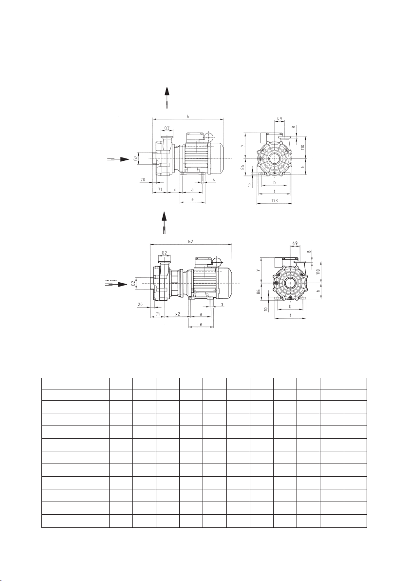
BADU®21-40; BADU®21-40/..-AK
Umwälzpumpen, normalsaugend
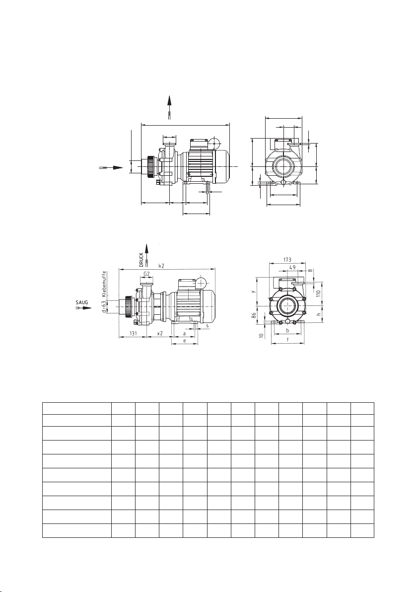
Maßzeichnung
Maße in mm
Typen a b e f h s x x2 y k k2
21-40/53 G 90 112 115 138 71 7,0 84 139 132 313 368
21-40/53 HG 90 112 115 138 71 7,0 84 139 132 313 368
21-40/54 G 90 112 115 138 71 7,0 84 139 132 313 368
21-40/54 HG 90 112 115 138 71 7,0 84 139 132 313 368
21-40/55 G 100 125 125 153 80 9,0 75 130 142 351 406
21-40/55 HG 100 125 125 153 80 9,0 75 130 142 351 406
21-40/55 H9G PU 100 140 155 170 90 10,0 81 136 142 351 406
21-40/56 G 100 125 125 153 80 9,0 75 130 127 351 406
21-40/56 HG 100 125 125 153 80 9,0 75 130 127 351 406
21-40/58 G 100 125 125 153 80 9,0 75 130 142 351 406
21-40/58 HG 100 125 125 153 80 9,0 75 130 142 351 406
Maßtabelle
Maße in mm
2
Technische Änderungen vorbehalten!
BADU 21-40/5. G
VD 21.04.540
VD 21.04.548
BADU 21-40/5. G-AK

3
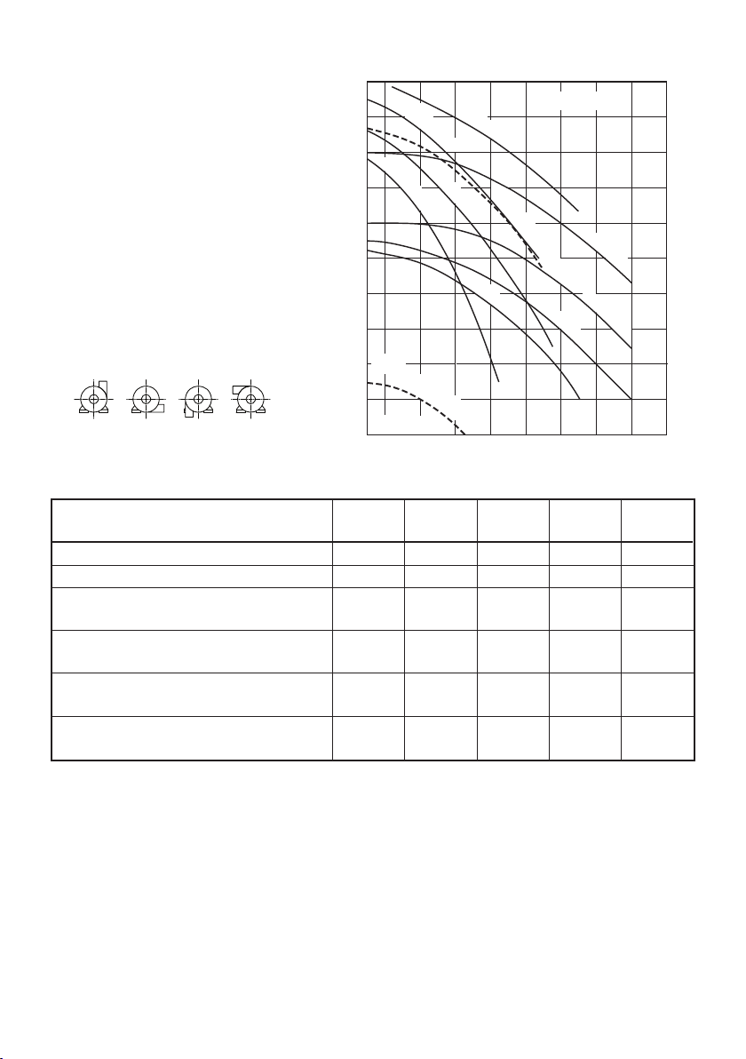
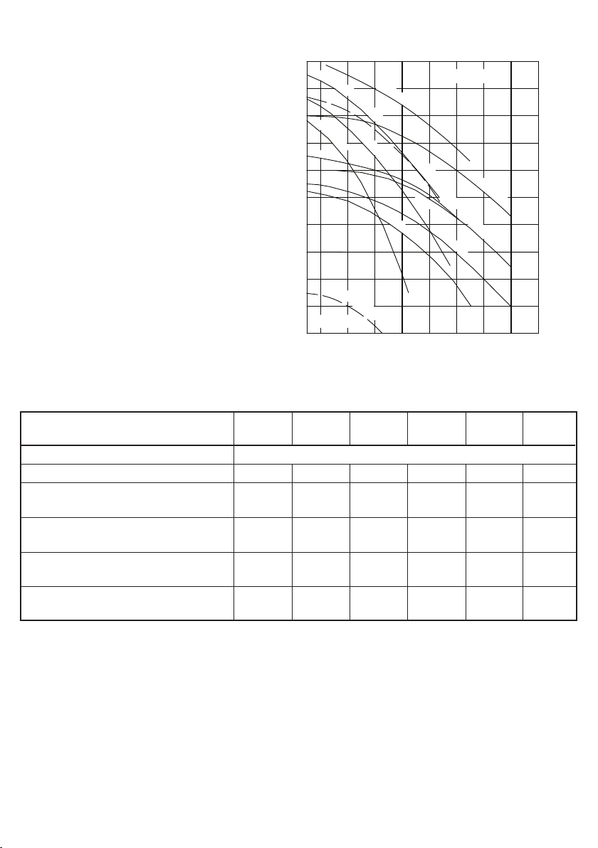
Kennlinien
BADU®21-40
BADU®21-40/..-AK
VKL 21.013-8
Schutzart IP 55
Wärmeklasse F
Drehzahl (min.
-1
) ca. 1420**)/2850
Dauerschalldruckpegel dB (A) ≤ 70
2)
Wassertemperatur (°C) max. 40
Gehäuseinnendruck (bar) max. 2,5
*)Auch mit Schlauchtüllen 50/40 oder
Klebestutzen 50/40 oder 63/40 lieferbar.
**
)
Gilt nur für BADU 21-40/55 H9G PU.
1)
Für Normspannung nach IEC 38 und DIN EN 60034
(Eurospannung).
Geeignet für Dauerbetrieb bei
1~ 220-240 V und bei 3~ Y/Δ 380-420 V / 220-240 V.
Toleranzen ± 5%.
2)
Gemessen mit Schallpegelmessgerät nach
DIN 45635.
3)
Gewinde nach DIN ISO 228 Teil 1 (eindichten mit
zusätzlichem Dichtring).
Gesamtförderhöhe H (m)
Förderstrom Q (m3/h)
Technische Daten bei 50 Hz BADU 21- 40/53 G 40/ 54 G 40 / 55 G
40/55 H9G PU
40/56 G 40/ 58 G
BADU 21- 40/53 HG 40/54 HG 40/55 HG 40/56 HG 40/58 HG
Saug/Druck (G)
3)
Außengewinde 2/2
*)
Empf. Saug-/Druckleitung, PVC-Rohr, d 63/63 63/63 63/63 63/63 63/63 75/75
Leistungsaufnahme P
1
(kW) 1~230 V 0,85 1,10 1,33 0,50/1,40 - 2,00
3~400/230 V - - - - 1,40 1,85
Leistungsabgabe P
2
(kW)1)1~230 V 0,55 0,75 1,00 0,22/1,00 - 1,50
3~400/230 V - - - - 1,10 1,50
Nennstrom (A) 1~230 V 4,20 5,00 6,50 2,30/6,70 - 8,80
3~400/230 V - - - - 2,40/4,20 3,25/5,60
Gewicht (kg) 1~ 9,5 9,5 13,8 14,8 - 15,0
3~ - - - - 11,5 13,0
4
6
8
12
10
14
16
20
18
22
2
n=2850 min
21-40/58 H
21-40/55 H
21-40/54 H
21-40/53
21-40/55
21-40/58
21-40/53 H
21-40/55 H9G PU
n=1420min
21-40/55 H9G PU
21-40/56
21-40/56 H
26 221410 18 26 30 34
21-40/54
-1
-1
4
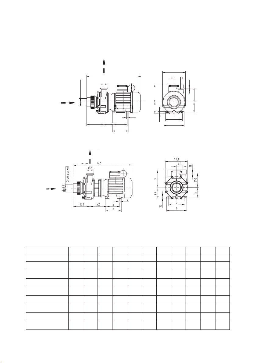
BADU®21-41; BADU®21-41/..-AK
Umwälzpumpen, normalsaugend
Maßzeichnung
Maße in mm
Typen a b e f h s x x2 y k k2
21-41/53 G 90 112 115 138 71 7,0 84 139 132 372 427
21-41/53 HG 90 112 115 138 71 7,0 84 139 132 372 427
21-41/54 G 90 112 115 138 71 7,0 84 139 132 372 427
21-41/54 HG 90 112 115 138 71 7,0 84 139 132 372 427
21-41/55 G 100 125 125 153 80 9,0 75 130 142 410 465
21-41/55 HG 100 125 125 153 80 9,0 75 130 142 410 465
21-41/55 H9G PU 100 140 155 170 90 10,0 81 136 142 410 465
21-41/58 G 100 125 125 153 80 9,0 75 130 142 410 465
21-41/58 HG 100 125 125 153 80 9,0 75 130 142 410 465
Klebemuffe
Glue socket
110
In
SAUG
e
130 x
a
d=63
s
10
f
b
86
h
DRUCK
G2
Out
y
8
49
k
173
Maßtabelle
Maße in mm
Technische Änderungen vorbehalten!
BADU 21-41/5.
VD 21.41.001
VD 21.41.002
BADU 21-41/5.-AK
5
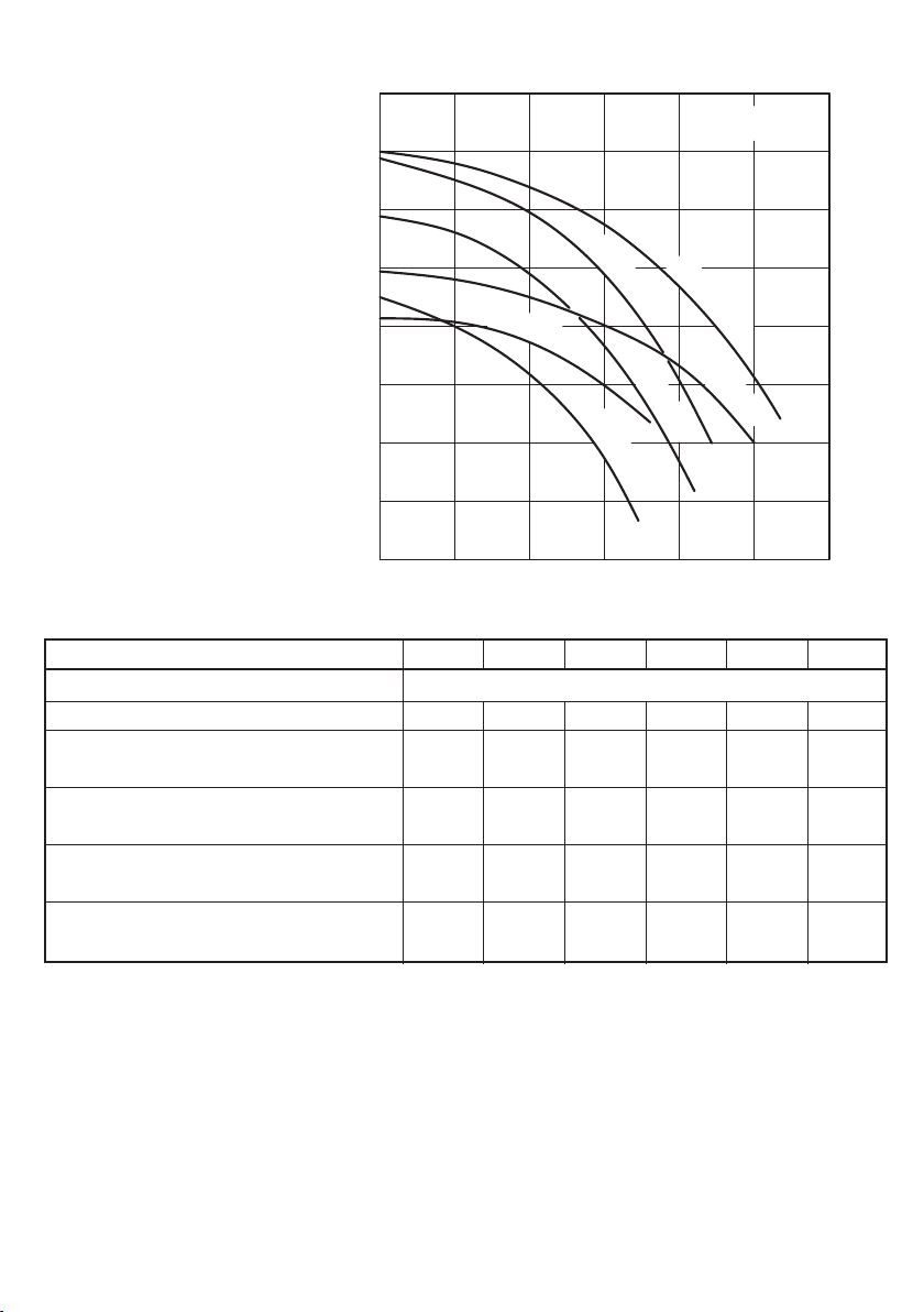
Kennlinien
BADU®21-41
BADU®21-41/..-AK
VKL 21.41.001
21-41/55
21-41/53
10
Total dynamic head H (m)
n=1420 min
21-41/55 H9G PU
Gesamtförderhöhe /
2
2
4
6
8
21-41/54
22
146-110 18
26 30 34
21-41/53 H
21-41/55 H
16
12
14
18
20
22
n=2850 min
21-41/54 H
21-41/55 H9G PU
21-41/58 H
21-41/58
-1
Schutzart IP 55
Wärmeklasse F
Drehzahl (min.
-1
) ca. 1420**)/2850
Dauerschalldruckpegel dB (A) ≤ 70
2)
Wassertemperatur (°C) max. 40
Gehäuseinnendruck (bar) max. 2,5
*)Druckstutzen auch mit Schlauchtülle 40
oder Klebestutzen 40 lieferbar.
**
)
Gilt nur für BADU 21-41/55 H9G PU.
1)
Für Normspannung nach IEC 38 und DIN EN 60034
(Eurospannung).
Geeignet für Dauerbetrieb bei
1~ 220-240 V und bei 3~ Y/Δ 380-420 V / 220-240 V.
Toleranzen ± 5%.
2)
Gemessen mit Schallpegelmessgerät nach
DIN 45635.
3)
Gewinde nach DIN ISO 228 Teil 1(eindichten mit
zusätzlichem Dichtring).
Gesamtförderhöhe H (m)
Förderstrom Q (m3/h)
Technische Daten bei 50 Hz BADU 21- 41/53 G 41/54 G 41/ 55 G
41/55 H9G PU
41/58 G
BADU 21- 41/53 HG 41/54 HG 41/55 HG 41/58 HG
Saug Klebemuffe d/Druck (G)
3)
63/2*
)
63/2*
)
63/2*
)
63/2*
)
63/2*
)
Empf. Saug-/Druckleitung, PVC-Rohr, d 63/63 63/63 63/63 63/63 75/75
Leistungsaufnahme P
1
(kW) 1~230 V 0,85 1,10 1,33 0,50/1,40 2,00
3~400/230 V - - - - 1,85
Leistungsabgabe P2(kW)1)1~230 V 0,55 0,75 1,00 0,22/1,00 1,50
3~400/230 V - - - - 1,50
Nennstrom (A) 1~230 V 4,20 5,00 6,50 2,30/6,70 8,80
3~400/230 V - - - - 3,25/5,60
Gewicht (kg) 1~ 9,5 9,5 13,8 14,8 15,0
3~ - - - - 13,0
0° (RO) 90° (UR) 180° (LU) 270° (OL)
Druckstutzenstellung
(auf Saugstutzen gesehen)
Möglichkeiten bei: BADU 21-40/5. und
BADU 21-41/5.
Standard-Druckstutzenstellung: 0° (RO)
D 21.023-2

6
BADU®21-50 und BADU®21-60;
Umwälzpumpen, normalsaugend
Maßzeichnung
Maße in mm
Motor
1~
Motor
3~
Typ abefhksxyabefhksxy
21-50/42 G
125 140 155 170 90 358 9 85 139 100 125 125 156 80 333 9 94 129
21-50/43 G
125 140 155 170 90 358 9 85 139 100 140 130 170 90 325 9 85 139
21-50/44 G
100 140 155 170 90 373 9 100 139 125 140 155 170 90 373 9 100 139
21-60/43 G
125 140 155 170 90 358 9 85 139 100 140 130 170 90 325 9 85 139
21-60/44 G
100 140 130 170 90 373 9 100 139 125 140 155 170 90 373 9 100 139
21-60/46 G
140 160 176 195 100 427 12 107 154 125 140 155 170 90 373 9 100 139
22
G2 /
10
60
x
k
e
s
h
b
y
f
85
G2 /
107
112
4
3
3
4
SAUG
In
Out
DRUCK
a
Maßtabelle
Maße in mm
Technische Änderungen vorbehalten! VD 21.05.410-1

7
BADU®21-50/..AK und BADU®21-60/..AK
Umwälzpumpen, normalsaugend
Maßzeichnung
Maße in mm
Motor
1~
Motor
3~
Typ abefhksxyabefhksxy
21-50/42 G
125 140 155 170 90 423 9 150 140 100 140 130 170 90 398 9 150 140
21-50/43 G
125 140 155 170 90 423 9 150 140 100 140 130 170 90 398 9 150 140
21-50/44 G
100 140 130 170 90 423 9 150 148 125 140 155 170 90 423 9 150 140
21-60/43 G
125 140 155 170 90 423 9 150 140 100 140 130 170 90 398 9 150 140
21-60/44 G
100 140 130 170 90 423 9 150 148 125 140 155 170 90 423 9 150 140
21-60/46 G
140 160 176 195 100 477 12 157 155 125 140 155 170 90 423 9 150 140
Maßtabelle
Maße in mm
Technische Änderungen vorbehalten! VD 21.05.420
8
Kennlinien
BADU®21-50
und
BADU
®
21-60
VKL 21.011-4
n=2850min
21-50/42
21-50/43
21-60/44
6
8
10
0
10
20 30
40
50
21-60/43
14
12
16
18
20
22
21-50/44
21-60/46
60
-1
Schutzart IP 55
Wärmeklasse F
Drehzahl (min.
-1
) ca. 2850
Dauerschalldruckpegel dB (A) ≤ 75
2)
Wassertemperatur (°C) max. 60
Gehäuseinnendruck (bar) max. 2,5
1)
Für Normspannung nach IEC 38 und DIN EN 60034
(Eurospannung).
Geeignet für Dauerbetrieb bei
1~ 220-240 V und bei 3~ Y/Δ 380-420 V / 220-240 V.
Toleranzen ± 5%.
2)
Gemessen mit Schallpegelmessgerät nach DIN 45635.
3)
Gewinde nach DIN ISO 228 Teil 1(eindichten mit
zusätzlichem Dichtring).
*
)
Auch mit Außengewinden G 21/2 G 2 oder Tüllenanschlüssen ø 52/52 mm (BADU 21-50) bzw. ø 72/52 mm
(BADU 21-60) lieferbar.
Gesamtförderhöhe H (m)
Förderstrom Q (m3/h)
Technische Daten bei 50 Hz BADU 21- 50 / 42 G 50/43 G 50 / 44 G 60/43 G 60/44 G 60 / 46 G
Saug/Druck (G)
3)
Außengewinde 23/4/23/4
*
)
Empf. Saug-/Druckleitung, PVC-Rohr, d 90/75 90/75 90/75 90/75 90/75 90/75
Leistungsaufnahme P
1
(kW) 1~230 V 1,63 2,30 2,90 2,30 2,90 3,90
3~Y/Δ 400/230 V
1,45 2,10 2,70 2,10 2,70 3,80
Leistungsabgabe P
2
(kW)1)1~230 V 1,10 1,60 2,20 1,60 2,20 3,00
3~Y/Δ 400/230 V
1,10 1,60 2,20 1,60 2,20 3,00
Nennstrom (A) 1~230 V 7,20 10,00 13,00 10,00 13,00 17,00
3~Y/Δ 400/230 V
2,55/4,40 3,40/5,90 4,60/8,00 3,40/5,90 4,60/8,00 6,20/10,70
Gewicht (kg) 1~ 16,5 16,5 18,3 16,5 18,3 22,5
3~ 13,0 14,5 16,0 14,5 16,0 16,5
9
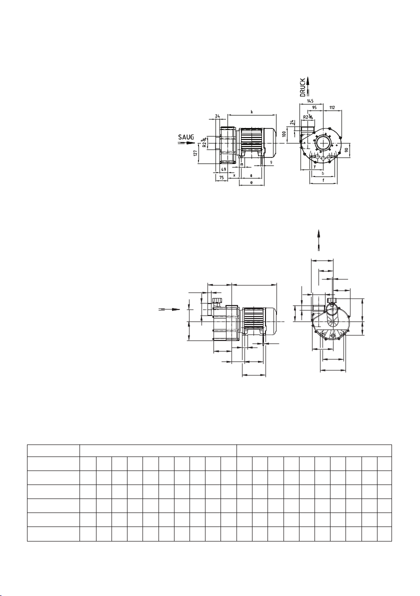
BADU®21-80
Umwälzpumpen, normalsaugend und selbstansaugend
Δ)
Maßzeichnung
Maße in mm
Motor
1~
Motor
3~
Typ abefhmsxykabefhmsxyk
21-80/31RG
125 140 155 170 90 36 9 85 139 298 100 140 130 170 90 36 9 85 139 265
21-80/32 RG
125 140 155 170 90 36 9 100 139 313 125 140 155 170 90 36 9 100 139 313
21-80/32 G
----------12514015517090369100139313
21-80/33 G
140 160 176 195 100 43 12 107 154 367 125 140 155 170 90 36 9 100 139 313
21-80/34 G
----------1401601761951004312107154347
D21.08.517-2
SAUG
In
Out
DRUCK
120
127
80
160
R2 /
24
e
xma
s
y
f
b
h
k
100
24
7
4
R2 /
3
112
145
95
153
4
3
Maßtabelle
Maße in mm
Technische Änderungen vorbehalten!
D 21.08.517-1
D 21.08.517-2
normalsaugend
Saug- und Druckanschluss bei
BADU 21-80/31 G bis BADU 2180/34 G mit Außengewinde R 2
3
/4,
bei BADU 21-80/31 bis BADU
21-80/34 mit Schlauchtülle 82 mm
selbstansaugendΔ)(bedingt bis 0,5 m)
Saug- und Druckanschluss bei
BADU 21-80/32 SG bis BADU
21-80/33 SG mit Außengewinde
R 2
3
/4, bei BADU 21-80/32 S bis
21-80/33 SΔ)mit Schlauchtülle 82 mm
10
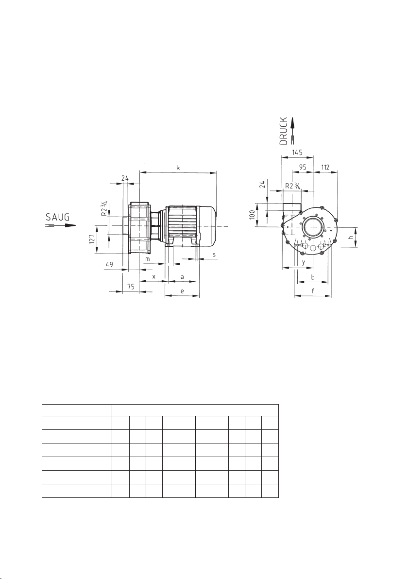
BADU®21-80/..-AK
Umwälzpumpen, normalsaugend
Maßzeichnung
Maße in mm
Motor
3~
Typ abef hmsxyk
21-80/31RG
100 140 130 170 90 36 9 135 139 338
21-80/32 RG
125 140 155 170 90 36 9 150 139 363
21-80/32 G
125 140 155 170 90 36 9 150 139 363
21-80/33 G
125 140 155 170 90 36 9 150 139 363
21-80/34 G
140 160 176 195 100 43 12 157 154 397
Maßtabelle
Maße in mm
Technische Änderungen vorbehalten!
VD 21.08.547

11
Kennlinien
BADU®21-80
BADU
®
21-80/..-AK
VKL 21.08.525-4
8
4
6
21-80/31R
21-80/32R
21-80/32
21-80/33
21-80/34
14
10
12
16
18
20
n=2850 min
-1
10 20 30 40 50 60 70 80 10090
Schutzart IP 55
Wärmeklasse F
Drehzahl (min.
-1
) ca. 2850
Dauerschalldruckpegel dB (A) ≤ 78,5
2)
Wassertemperatur (°C) max. 70
Gehäuseinnendruck (bar) max. 2,5
*
)
Einschaltstrom ca. 82 A
**)Pumpen auch mit Tüllenanschlüssen
82 mm lieferbar!
1)
Für Normspannung nach IEC 38 und DIN EN 60034
(Eurospannung).
Geeignet für Dauerbetrieb bei
1~ 220-240 V und bei 3~ Y/Δ 380-420 V / 220-240 V
3~ Y/Δ 690-400 V - bei 21-80/34 G
Toleranzen ± 5%.
2)
Gemessen mit Schallpegelmessgerät nach DIN 45635.
3)
Außengewinde nach DIN 2999 Teil 1 und ISO 7/1,
(eindichten nur mit Teflonband)
Gesamtförderhöhe H (m)
Förderstrom Q (m3/h)
Technische Daten bei 50 Hz BADU 21-
80/31 RG 80/32 RG
80/32 G 80 / 33 G 80/34 G
Saug/Druck (R)
3)
Außengewinde 23/4/23/4 **
)
Empf. Saug-/Druckleitung, PVC-Rohr, d 110/110 110/110 110/110 140/110 140/110
Leistungsaufnahme P
1
(kW) 1~230 V 2,30 2,90 - 3,90 -
3~Y/Δ 400/230 V
2,10 2,70 3,30 3,80 4,85
Leistungsabgabe P
2
(kW)1)1~230 V 1,60 2,20 - 3,00 -
3~Y/Δ 400/230 V
1,60 2,20 2,60 3,00 4,00
Nennstrom (A) 1~230 V 10,00 13,00 - 17,00
*
)
-
3~Y/Δ 400/230 V
3,40/5,90 4,60/8,00 5,60/9,70 6,20/10,70Δ 400-7,80
Gewicht (kg) 1~ 18,5 20,0 - 24,5 -
3~ 16,5 18,0 18,0 18,5 22,5
Der Betriebspunkt sollte im angegebenen Leistungsbereich liegen, sonst erhöhter Dauerschalldruckpegel! Dieser ist im unteren Bereich der Kennlinie um so höher, je niedriger der Druck auf
der Saugseite der Pumpe ist.
12
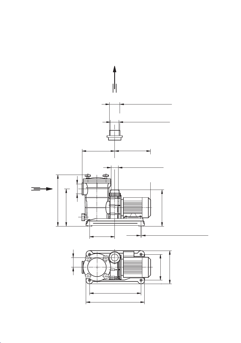
BADU®FA 21-50, BADU®FA 21-60 und BADU®FA 21-80
Umwälzpumpen mit Fasernfänger normalsaugend
Maßzeichnung
Maße in mm
Technische Änderungen vorbehalten!
D 21.05.408-2
85 (95)
510
225
450
290
~
bei FA 21-50/36
Innendurchmesser
FA 21-60/46
8 tief
4 x Innengewinde
285 (295)
449
325
Rp3
Ø63
313
SAUG
220
317 (323)
M8
Außendurchmesser
Innendurchmesser
Ø90
Ø75
bei
FA 21-80/56
DRUCK
FA 21-80/56
für
Maße ( )

13
Kennlinien
BADU®FA 21-50,
BADU®FA 21-60,
BADU®FA 21-80,
VKL 21.012-6
0
8
10
10
20 30
40
70
50
60
FA21-60/45
14
12
16
18
20
22
FA21-80/56
n=2850min
FA21-50/36
-1
Schutzart IP 55
Wärmeklasse F
Drehzahl (min.
-1
) ca. 2850
Dauerschalldruckpegel dB (A) ≤ 78,5
2)
Wassertemperatur (°C) max. 60
Gehäuseinnendruck (bar) max. 2,5
1)
Für Normspannung nach IEC 38 und DIN EN 60034
(Eurospannung).
Geeignet für Dauerbetrieb bei
1~ 220-240 V und bei 3~ Y/Δ 380-420 V / 220-240 V.
Toleranzen ± 5%.
2)
Gemessen mit Schallpegelmessgerät nach DIN 45635.
3)
Innengewinde nach DIN 2999 Teil 1 und ISO 7/1,
(eindichten nur mit Teflonband)
Gesamtförderhöhe H (m)
Förderstrom Q (m3/h)
Der Betriebspunkt sollte im angegebenen Leistungsbereich liegen, sonst erhöhter Dauerschalldruckpegel! Dieser ist im unteren Bereich der Kennlinie um so höher, je niedriger der Druck auf
der Saugseite der Pumpe ist.
Technische Daten bei 50 Hz BADU FA 21-50/36 FA 21- 60 /45 FA 21- 80 / 56
Saug/Druck (Rp3))/d 3/63 3/63
3/75 oder 90
Empf. Saug-/Druckleitung, PVC-Rohr, d 90/90 90/90 110/110
Leistungsaufnahme P1(kW)
3~Y/Δ 400/230 V
2,70 3,30 3,80
Leistungsabgabe P2(kW)1)3~Y/Δ 400/230 V
2,20 2,60 3,00
Nennstrom (A)
3~Y/Δ 400V
4,60 5,60 6,20
Nennstrom (A)
3~Y/Δ 230V
8,00 9,70 10,70
Gewicht (kg) 3~ 20,0 22,0 25,0
14
2. Sicherheit
Diese Betriebsanleitung enthält grundlegende Hinweise, die bei Aufstellung,
Betrieb und Wartung zu beachten sind. Daher ist diese Betriebsanleitung unbedingt vor Montage und Inbetriebnahme vom Monteur sowie dem zuständi gen
Fachpersonal/Betreiber zu lesen und muss ständig am Einsatzort der Ma schi ne/
Anlage verfügbar sein.
Es sind nicht nur die unter diesem Hauptpunkt Sicherheit aufgeführten, allgemeinen Sicherheitshinweise zu beachten, sondern auch die unter den anderen
Hauptpunkten eingefügten, speziellen Sicherheitshinweise, so z.B. für den privaten Gebrauch.
Dieses Gerät ist nicht dafür bestimmt durch Personen (einschließlich Kinder) mit
eingeschränkten physischen, sensorischen oder geistigen Fähigkeiten oder
mangels Erfahrung und/oder mangels Wissen benutzt zu werden, es sei denn,
sie werden durch eine für ihre Sicherheit zuständige Person beaufsichtigt oder
erhielten von ihnen ihre Anweisungen, wie das Gerät zu benutzen ist. Kinder sollten beaufsichtigt werden, um sicherzustellen, dass sie nicht mit dem Gerät spielen.
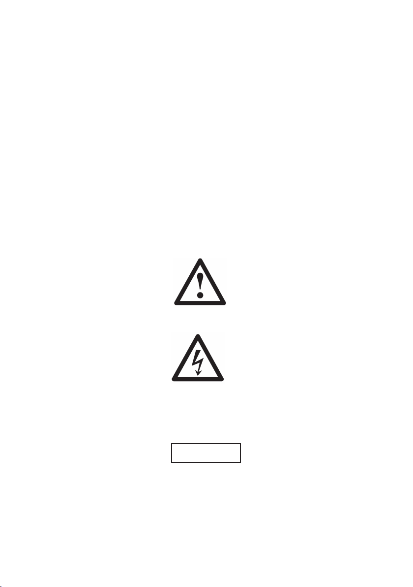
2.1 Kennzeichnung von Hinweisen in der Betriebsanleitung
Die in dieser Betriebsanleitung enthaltenen Sicherheitshinweise, die bei Nichtbeachtung Gefährdungen für Personen hervorrufen können, sind mit allgemeinen Gefahrensymbolen
Sicherheitszeichen nach DIN 4844 - W 9
bei Warnung vor elektrischer Spannung mit
Sicherheitszeichen nach DIN 4844 - W 8
besonders gekennzeichnet.
Bei Sicherheitshinweisen, deren Nichtbeachtung Gefahren für die Maschine und
deren Funktionen, sowie Schäden an der Umgebung hervorrufen kann, ist das
Wort
eingefügt.
Direkt an der Maschine angebrachte Hinweise wie z.B.
– Drehrichtungspfeil
– Kennzeichen für Fluidanschlüsse
– Typenschild
müssen unbedingt beachtet und in vollständig lesbarem Zustand gehalten
werden.
ACHTUNG

15
2.2 Personalqualifikation und -schulung
Das Personal für Bedienung, Wartung, Inspektion und Montage muss die ent-
sprechende Qualifikation für diese Arbeiten aufweisen. Verantwortungsbereich,
Zuständigkeit und die Überwachung des Personals müssen durch den Betreiber
genau geregelt sein. Liegen bei dem Personal nicht die notwendigen Kenntnisse
vor, so ist dieses zu schulen und zu unterweisen. Dies kann, falls erforderlich, im
Auftrag des Betreibers der Maschine durch den Hersteller/Lieferanten erfolgen.
Weiterhin ist durch den Betreiber sicherzustellen, dass der Inhalt der Betriebsanleitung durch das Personal voll verstanden wird.
2.3 Gefahren bei Nichtbeachtung der Sicherheitshinweise
Die Nichtbeachtung der Sicherheitshinweise kann sowohl eine Gefährdung für
Personen als auch für Umwelt, Maschine und Umgebung zur Folge haben. Die
Nichtbeachtung der Sicherheitshinweise kann zum Verlust jeglicher Schadensersatzansprüche führen.
Im einzelnen kann Nichtbeachtung beispielsweise folgende Gefährdungen
nach sich ziehen:
– Versagen wichtiger Funktionen der Maschine/Anlage
– Versagen vorgeschriebener Methoden zur Wartung und Instandhaltung
–Gefährdung von Personen durch elektrische, mechanische und chemische
Einwirkungen
– Gefährdung der Umwelt durch Leckage von gefährlichen Stoffen
– Beschädigung von Einrichtungen und Bauwerken
2.4 Sicherheitsbewusstes Arbeiten
Die in dieser Betriebsanleitung aufgeführten Sicherheitshinweise, die beste -
henden nationalen Vorschriften zur Unfallverhütung sowie eventuelle interne
Arbeits-, Betriebs- und Sicherheitsvorschriften des Betreibers sind zu beachten.
2.5 Allgemeine Sicherheitshinweise für den Betreiber / Bediener
Führen heiße oder kalte Maschinenteile zu Gefahren, müssen diese Teile bau-
seitig gegen Berührung gesichert sein.
Berührungsschutz für sich bewegende Teile (z.B. Kupplung) darf bei sich in
Betrieb befindlicher Maschine nicht entfernt werden.
Leckagen (z.B. der Wellendichtung) gefährlicher Fördergüter (z.B. explosiv,
giftig, korrosiv, heiß) müssen so abgeführt werden, dass keine Gefährdung für
Personen, Sachen und die Umwelt entsteht. Gesetzliche Bestimmungen sind
einzuhalten.
Gefährdungen durch elektrische Energie sind auszuschließen, Einzelheiten
hierzu siehe z.B. in den Vorschriften des VDE und der örtlichen Energiever sorgungsunternehmen.

16
2.6 Sicherheitshinweise für Wartungs-, Inspektions- und Montagearbeiten
Der Betreiber hat dafür zu sorgen, dass alle Wartungs-, Inspektions- und Mon -
tagearbeiten von autorisiertem und qualifiziertem Fachpersonal ausgeführt
werden, das sich durch eingehendes Studium der Betriebsanleitung ausrei chend informiert hat.
Die Unfallverhütungsvorschriften sind zu beachten.
Grundsätzlich sind Arbeiten an der Maschine nur im Stillstand im elektrisch
spannungsfreien Zustand durchzuführen. Die in der Betriebsanleitung beschriebene Vorgehensweise zum Stillsetzen der Maschine muss unbedingt eingehalten werden.
Pumpen oder -aggregate, die gesundheitsgefährdende Medien fördern, müssen
dekontaminiert werden.
Unmittelbar nach Abschluss der Arbeiten müssen alle Sicherheits- und Schutzeinrichtungen wieder angebracht bzw. in Funktion gesetzt werden.
Vor der Wiederinbetriebnahme sind die im Abschnitt Erstinbetriebnahme aufgeführten Punkte zu beachten.
2.7 Eigenmächtiger Umbau und Ersatzteilherstellung
Umbau oder Veränderungen der Maschine sind nur nach Absprache mit dem
Hersteller zulässig. Originalersatzteile und vom Hersteller autorisiertes Zubehör
dienen der Sicherheit. Die Verwendung anderer Teile kann die Haftung für die
daraus entstehenden Folgen aufheben.
2.8 Unzulässige Betriebsweisen
Die Betriebssicherheit der gelieferten Maschine ist nur bei bestimmungsgemäßer
Verwendung entsprechend Abschnitt 1 – Allgemeines – der Betriebsanleitung
gewährleistet. In den Datenblättern angegebene Grenzwerte dürfen auf keinen
Fall überschritten werden. Pumpen dürfen nur im Bereich der angegebenen
Kennlinien betrieben werden.
Zitierte Normen und andere Unterlagen
DIN 4844 Teil 2 Sicherheitskennzeichnung:
Darstellung von Sicherheitszeichen
3. Transport und Zwischenlagerung
3.1 Längere Zwischenlagerung in einer Umgebung mit hoher Luftfeuchtigkeit und
wechselnden Temperaturen ist zu vermeiden. Kondenswasserbildung kann
Motorwicklungen und Metallteile angreifen. In diesem Fall erlischt die Gewährleistung.
3.2
Nur geeignete und technisch einwandfreie Hebezeuge sowie Lastaufnahmemittel mit ausreichender Tragkraft verwenden!
ACHTUNG

17
4. Beschreibung
Die Kunststoffpumpen der Baureihe BADU 21und BADU FA 21 sind zur Förderung von Flüssigkeiten in Kombination mit weiteren Anlagenteilen konzipiert.
Die Motorwelle dient gleichzeitig als Pumpenwelle, auf der das Laufrad befestigt
ist. Als Wellendichtung dient eine Balg-Gleitringdichtung, die auf einer Laufradnabe aus Kunststoff sitzt. Hierdurch ist eine sichere Trennung zwischen
Schwimmbadwasser und Elektromotor gegeben. Diese Nabe dient als Wellenschutzhülse. Durch die Blockbauweise haben die Pumpen einen geringen Platzbedarf. Sie werden durch Dreh- oder Wechselstrommotoren angetrieben.
5. Aufstellung / Einbau
5.1
Die Pumpe ist mit einem Motor der Schutzart IP 55 ausgestattet. Wir empfehlen
aber trotzdem, bei der Aufstellung im Freien einen einfachen Regenschutz vorzusehen. Dies erhöht die Lebensdauer Ihrer Pumpe. In einem geschlossenem
Raum wie z. B. Keller, muss unbedingt ein Wasserablauf vorhanden sein.
Die Größe des Bodenablaufs richtet sich vor allem nach der Größe des
Schwimmbeckens, dem Umwälzvolumenstrom aber auch nach der Möglichkeit
möglicher Leckagen im Badewasserumwälzsystem.
In einem Aufstellungsraum muss für eine ausreichende Be- und Entlüftung
gesorgt werden, damit sich zum einen kein Kondenswasser bilden kann und zum
anderen eine ausreichende Kühlung der Pumpenmotoren und anderen Anlagenteilen z. B. Schaltschränke und Steuergeräte vorhanden ist. Eine Umgebungstemperatur von 40°C darf keinesfalls überschritten werden.
Die Aufstellung der Pumpen sowie die Ausführung der Installationsarbeiten muss
so erfolgen, dass sowohl Körper- als auch Luftschallübertragungen reduziert
werden. Hierzu sind die einschlägigen Vorschriften z. B. DIN 4109 zu beachten.
Die Aufstellung der Pumpen kann z. B. auf einem Fundament mit Korkeinlagen
erfolgen oder auf schwingunsabsorbierenden Materialien (z.B. Schaumstoffe mit
entsprechender Härte). Rohrleitungen sind stets spannungsfrei anzuschließen
und gegebenenfalls elastisch zu lagern. Erforderlichenfalls sind Rohrleitungskompensatoren einzubauen.
Es ist darauf zu achten, dass ausreichend Abstand zwischen Motorlüfterhaube
und Wand vorhanden ist mind. 50 mm. Bei den Pumpentypen BADU FA 21,
muss auch genügend Platzreserve nach oben vorhanden sein mind. 220 mm,
damit das Saugsieb (143) ausgebaut werden kann. Zur Befestigung der Pumpe
sind ausschließlich Schrauben, Gewinde oder Dübel im Fundament zu verwenden, um einen Ausbau der Motoreinheit nicht zu blockieren. Saug- und Druckleitung sind spannungsfrei am Pumpengehäuse anzubringen.
Achtung: Die ABS-Verklebungen, Bundbuchse (721.1), benötigen eine längere
Aushärtezeit. Inbetriebnahme erst nach mindestens 12 Stunden möglich.
5.2 Installation
Die Pumpe darf keinesfalls als Festpunkt für die Rohrleitung verwendet werden.
Vom Rohrleitungssystem dürfen keine Kräfte und Momente (z. B. durch Verwin-
ACHTUNG

18
dung, Wärmeausdehnung) auf die Pumpe wirken. Die Rohre sind unmittelbar vor
der Pumpe abzufangen und spannungsfrei anzuschließen. Das sollte unter Verwendung geeigneter Kompensatoren geschehen.
Bei Überschreitung der Rohrleitungskräfte können, z. B. undichte Stellen an der
Pumpe selbst oder an den Flanschverbindungen entstehen, die zum heftigen
Austritt des Fördermediums führen.
Die Saugleitung ist zur Pumpe kontinuierlich steigend, bei Zulauf kontinuierlich
fallend zu verlegen, um Luftsackbildung zu vermeiden.
Der Einbau von Rückflussverhinderern und Absperrorganen ist, je nach Art der
Anlage und der Pumpe, zu empfehlen.
Durch Temperatur entstehende Ausdehnungen der Rohrleitungen müssen durch
geeignete Maßnahmen abgefangen werden. Wir empfehlen, Kompensatoren
unmittelbar zwischen Pumpe und Rohrleitung einzubauen.
Plötzlich (schlagartig) schließende Armaturen in Rohrleitungen sind unbedingt zu
vermeiden. Die dabei auftretenden Druckstöße können den maximal zulässigen
Gehäusedruck der Pumpe um ein Mehrfaches übersteigen! Zur Vermeidung zu
starker Druckstöße sind Druckstoßdämpfer oder Windkessel einzubauen.
5.3
Mechanisch / hydraulisch:
Die Pumpe muss horizontal und trocken aufgestellt werden. Sie kann sowohl
unterhalb (Zulaufbetrieb, max. 3m) als auch oberhalb des Wasserniveaus
(Saugbetrieb) montiert werden. Hierbei darf die Saughöhe zwischen Wasserspiegel und Pumpe (geodätische Höhe) 5m nicht überschreiten. Die Saughöhe
wird durch Strömungswiderstände in der Saugleitung bei längeren und/oder
zu klein bemessenen Rohrleitungen erheblich herabgesetzt.
Die in den Tabellen angegebenen Rohrleitungsdimensionen für die Saugleitun-
gen gelten nur für eine Leitungslänge von maximal 5 m.
Längere Rohrleitungen erhöhen den Widerstand und verschlechtern das An saugverhalten. Die Gefahr der Kavitationsbildung nimmt ebenfalls zu. Es ist auf
Dichtigkeit der Saugleitung zu achten, denn bei undichter Saugleitung
saugt die Pumpe schlecht oder gar nicht an. Die Pumpenanschlüsse bei
BADU 21-80/.. und BADU FA 21-80/56 dürfen nur mit Dichtungsband abgedichtet werden.
Die Saugleitung soll so kurz wie möglich sein. Dadurch verringert sich die
Ansaugzeit, die vom Luftvolumen in der Saugleitung abhängig ist. Bei sehr langen Saugleitungen kann sie bis zu 12 min. betragen. Die Saugleitung sollte bis
zur Pumpe möglichst unter dem Niveau des Wasserspiegels verlegt werden. Es
ist erforderlich, dort, wo die Pumpe über dem Wasserspiegel installiert wird, in
der Saugleitung ein Fußventil einzubauen. Die Saugleitung kann sich somit beim
Stillstand der Pumpe nicht entleeren.
Zulaufbetrie
b:
Die Pumpe kann unterhalb des Flüssigkeitsspiegels (max. 3m) aufgestellt werden. Dabei muss die Pumpe nicht aufgefüllt werden, jedoch muss die Möglichkeit bestehen, das Pumpengehäuse und die Saugleitung zu entlüften, damit sich
der Pumpenkörper mit Flüssigkeit füllt und die Pumpe nicht trocken läuft.
ACHTUNG
19
Saugbetrieb:
Bei Aufstellung der Pumpe über dem Flüssigkeitsniveau muss in die Saugleitung
ein Fußventil eingebaut werden. Es muss die Möglichkeit bestehen, das Pumpengehäuse und die Saugleitung vor Inbetriebnahme mit Flüssigkeit zu füllen.
Die Saugleistung wird durch Strömungswiderstände in der Saugleitung bei längeren und/oder zu eng bemessenen Rohrleitungen erheblich herabgesetzt. Deshalb soll die Saugleitung so kurz wie möglich sein.
Bei undichter Saugleitung saugt die Pumpe nicht.
5.4
Gefahr der Verstopfung
Baureihe BADU 21:
Falls die Möglichkeit einer Verstopfung (Stroh, Laub, Gras usw.) nicht auszu schließen ist, muss ein Sieb in der Zulauf- oder Saugleitung eingebaut werden.
Baureihe BADU FA 21:
Bei Baureihe BADU FA 21 ist ein Saugsieb (143) im Fasernfänger eingebaut.
5.5
Elektrisch: Elektroanschluss nur durch einen Fachmann!
Vor Durchführung der Elektroarbeiten oder Wartungsarbeiten sind alle Teile
spannungsfrei zu machen.
Bitte darauf achten, dass in der Elektroinstallation eine Trennvorrichtung vor gesehen ist, die das Abtrennen vom Netz mit mindestens 3mm Kontaktöffnung
jedes Poles gestattet. Diese Pumpe ist nach Schutzklasse I gebaut.
Die Um gebungstemperatur darf max. 40°C nicht überschreiten. Bei Pumpen mit
Drehstrommotoren muss ein richtig eingestellter Motorschutzschalter installiert
sein. Bitte die Werte auf dem Typenschild beachten. Es erlischt sonst jeglicher
Ge währleistungsanspruch bei Motorschaden. Bei Wechselstrommotoren der Baureihen BADU 21-40/.. und BADU 21-41/.. ist dieser Motorschutzschalter oder ein
automatisch schaltender Temperaturwächter eingebaut. Bei allen anderen Typen
der Baureihe BADU 21und BADU FA 21ist dieser bauseits vorzu sehen.
Die Motoren sind nach ISO Kl. F (Wärmeklasse) gebaut und können außen an
den Rippen Temperaturen bis 70°C erreichen.
Vorsicht: Benutzung der Pumpe für Schwimmbecken und deren Schutz bereich nur zulässig, wenn diese nach DIN/VDE 0100 Teil 702 errichtet sind.
Bitte fragen Sie Ihren Elektrofachmann!
Der versorgende Stromkreis ist mit einer Fehlerstromschutzeinrichtung mit
einem Nennfehlerstrom von I
ΔN
≤ 30 mA zu schützen.
Zum Anschluss oder Wechsel der elektrischen Leitungen bei Motoren der Pumpenbaureihe BADU 21-40/..
und BADU 21-41/..
dürfen am Klemmkasten nur 3
ACHTUNG
20
Schrauben entfernt werden. Die 4. Schraube ist nur soweit zu lockern, bis der
Klemmkastendeckel weggedreht werden kann. Der Klemmkastenrahmen muss
am Motorgehäuse verbleiben.
Entsprechend der Norm müssen die Leitungstypen H05RN-F bzw. H07RN-F verwendet werden. Zusätzlich muss der zulässige Mindestquerschnitt entsprechend
der Motorleistung und der Leitungslänge angepasst werden.
Die Pumpen sind für festen elektrischen Anschluss vorgesehen.
6. Erstinbetriebnahme
6.1
Baureihe BADU 21:
Die Pumpe langsam mit sauberem Wasser bis zum Druckanschluss füllen.
Die Pumpe nicht trocken laufen lassen! Auch nicht zur Drehrichtungs kon trolle! Trockenlauf zerstört die Gleitringdichtung.
Baureihe BADU FA 21:
Den Deckel (160.3) des Fasernfängers lösen. Den Fasernfänger bzw. die Pumpe
langsam mit sauberem Wasser bis zum Sauganschluss füllen. Bitte darauf achten, dass die Dichtflächen am Deckel (160.3) und im Filtergehäuse (124) sauber
sind. Anschließend den Runddichtring (412.10) in die Filtergehäusedichtnut einlegen. Danach den Deckel (160.3) gerade einsetzen und die vier Kreuzgriffe
(925) gleichmäßig über Kreuz anziehen und darauf achten, dass er dicht aufsitzt.
Andernfalls kann die Pumpe nicht oder nicht mit voller Kraft ansaugen.
Die Pumpe nicht trocken laufen lassen! Auch nicht zur Drehrichtungskontrolle!
6.2
Pumpe vor Inbetriebnahme, nach längerer Stillstands- bzw. Lagerzeit, - auf
Leichtgängigkeit prüfen. Hierzu einen Schraubendreher in den Schlitz am Motorwellenende (Lüfterseite) stecken und von Hand in Motordrehrichtung durchdrehen. Oder, falls erforderlich, die Lüfterhaube entfernen und gleichfalls von Hand
am Lüfterrad im Motordrehrichtung drehen. Nach Inbetriebnahme auf Dichtigkeit
der Gleitdichtrichtung achten.
6.3
Die Pumpe darf nicht ohne Saugsieb (143) bzw. Saugsieb-Griff (Gefahr des
Aufschwimmens vom Saugsieb) in Betrieb genommen werden, da sie sonst verstopfen und blockieren könnte.
6.4
Bei Pumpen mit Drehstrommotor ist beim ersten Einschalten darauf zu achten,
dass der Motor sich in Richtung des aufgeklebten Pfeiles dreht. Ist dies nicht der
Fall, unbedingt einen Fachmann rufen! (Zwei Phasen tauschen).
ACHTUNG
ACHTUNG
ACHTUNG
ACHTUNG
21
6.5
Bitte darauf achten, dass die eingebauten Absperrorgane in Saug- und Druck leitung bei Betrieb völlig geöffnet sind, weil die Pumpe nie bei geschlossenen
Absperrorganen laufen darf!
7. Wartung / Instandhaltung
7.1
Baureihe BADU FA:
Das Saugsieb im Fasernfänger muss von Zeit zu Zeit gereinigt werden. Bei verschmutztem oder vollem Sieb geht der Förderstrom der Pumpe zurück und es
findet keine ausreichende Filtration statt. Es besteht Gefahr von Kavitation, die
schwerwiegende Schäden an verschiedenen Pumpenteilen verursacht.
Reinigen des Saugsiebe
s:
1. Pumpe ausschalten.
2. Absperrorgane schließen.
3. Deckel (160.3) öffnen. Saugsieb (143) herausnehmen, reinigen und wieder
einsetzen. Deckel schließen, (siehe Punkt 6.1 und 6.3).
4. Absperrorgane öffnen.
5. Pumpe wieder einschalten.
7.2
Wird die Pumpe durch den Wicklungsschutzkontakt oder dem Motorschutzschalter außer Betrieb gesetzt, ist die Stromzufuhr zu unterbrechen und zu prüfen, ob sich die Pumpe leicht durchdrehen lässt. Dazu die Motorwelle an der Lüfterseite mit einem Schraubendreher o.ä. durchdrehen. Ist die Motorwelle
schwergängig, muss die Pumpe von einem Fachmann überprüft werden. Ist sie
leichtgängig, Schraubendreher o.ä. herausziehen, Stromzufuhr wieder herstellen. Nach dem Abkühlen des Motors schaltet der Wicklungsschutzkontakt selbständig wieder ein, bzw. den Knopf des Motorschutzschalters wieder eindrücken.
Dies darf nur noch einmal geschehen. Bitte die Stromaufnahme überprüfen!
Nach einem weiteren Auslösen des Wicklungsschutzkontaktes oder des Motorschutzschalters, ist vom Fachmann die Ursache der Störung festzustellen (z.B.
Blockieren der Pumpe durch Verunreinigungen, Sand beim Bodenreinigen).
Stromzufuhr und Sicherungen kontrollieren.
7.3
Sitzt die Pumpe fest, muss sie von einem Fachmann gereinigt werden. Mehrmaliges Einschalten der blockierten Pumpe kann Motorschäden zur Folge haben. In
diesem Fall erlischt der Gewährleistungsanspruch!
ACHTUNG
ACHTUNG
ACHTUNG
ACHTUNG
22
7.4
Der Leckageabfluss unten zwischen Pumpengehäuse und Motor darf nicht verstopft/abgedichtet werden, da sonst das Wasser innen aufsteigt und der Motor
beschädigt wird! Stellen Sie bitte sicher, dass durch eventuelle Leckagen keine
Folgeschäden auftreten können! Gegebenenfalls ist eine entsprechende Auffangvorrichtung oder Leckageabfuhr vorzusehen.
7.5
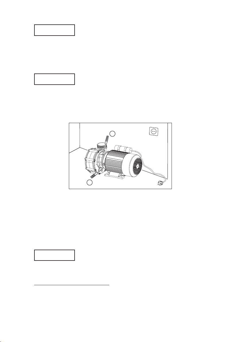
Entfernung von Salzkristallen bei Kunststofflaternen-Ausführung
In regelmäßigen Abständen ist zu prüfen, ob sich Kristalle an der Kunststofflaterne abgelagert haben (bedingt durch Salzwasser). Wenn ja, sind diese von der
Kunststofflaterne zu entfernen.
Vor Durchführung der Wartungsarbeiten sind alle Teile spannungsfrei zu
machen.
ACHTUNG
ACHTUNG
7.6 Wichtige Reparaturhinweise
Der Austausch ist von einem Fachmann vorzunehmen.
Demontage:
Austausch der Gleitringdichtun
g:
Die Pumpe ist auszuschalten und vom Netz zuverlässig zu trennen. Die Gleitring-
dichtung (433) muss immer komplett ausgetauscht werden. Zu diesem Zweck
muss nicht die ganze Pumpe ausgebaut werden (ausgenommen sind die Pum-
pen der Baureihe BADU 21-40/5. und BADU 21-41/5.). Es muss lediglich die
2
1
VW21.08.607
Mittels eines Schraubendreher o. ä. die vorhandenen Salzkristalle an der Laterne
von oben zwischen den Rippen vorsichtig lösen (1). Die abfallende Salzkruste
am Motorfuß (unten) entfernen (2).
Die Motorwelle muss von den Salzkristallen vollständig befreit und sichtbar sein.
Bitte prüfen, ob sich die Motorwelle leicht durchdrehen lässt. Dazu die Motorwelle an der Lüfterseite mit einem Schraubendreher o. ä. durchdrehen. Anschließend Stromzufuhr wieder herstellen.
ACHTUNG

23
Motoreinheit durch Lösen der 8 Innensechskantschrauben oder Kombischrauben
(914.1 bzw. 900.1) aus dem Gehäuse (107) ausgebaut werden.
Ausbau des Laufrades:
Bei den Typen BADU 21-40/5. und BADU 21-41/5. wird das Laufrad auf die
Motorwelle aufgeschraubt (Rechtsgewinde).
Mit einem Schraubendreher in den Schlitz der Motorwelle lüfterseitig fassen,
festhalten und Laufrad abdrehen.
Achtung: Bei Drehstrommotoren ist das Laufrad mit LOCTITE 480 (ähnlich
Cyanacrylat-Sofortklebstoff) gesichert, hierbei eventuell Motorlüfterflügel entfernen und Motorwelle einspannen.
Bei den Typen BADU 21-50/4., 21-60/4., 21-80/3. und BADU FA 21-50/36,
FA 21-60/45, FA 21-80/56 ist das Laufrad auf die Motorwelle aufgesteckt.
Die Hutmutter (922) mit Runddichtring (412.13) abschrauben. Das Laufrad
(230.1) vom Motor abziehen.
Montage:
Einbau der
neuen kompletten Gleitringdichtung:
Laufradnabe (230) und Manschette des kompletten Gegenringes leicht mit Seifenwasser befeuchten und mit beiden Daumen die Gleit ringdichtung (433) auf die
Laufradnabe aufpressen bzw. den Gegenring in den Gehäusedeckel (161) oder
in das Druckgehäuse (107) nur bei BADU 21-40/.. und BADU 21-41/.. einpressen.
Einbau des Laufrades:
Vor dem Wiedereinbau des Laufrades, Gleitfläche des Gegenringes und der
Gleitringdichtung säubern, z. B. mit Spiritus oder Papiertaschentuch.
Bei den Typen BADU 21-40/5. in umgekehrter Reihenfolge (siehe Ausbau).
Achtung: Bei Drehstrommotoren Pumpen 24 Stunden bei Raumtemperatur
stehen lassen, bis die Klebeverbindung (siehe Ausbau) Laufrad/Welle die Endfestigkeit erreicht hat.
Wiedereinbau des Laufrades bei BADU 21-5
0/4., 21-60/4., 21-80/3. und
BADU FA 21-50/36, BADU FA 21-60/45, BADU FA 21-80/56
Zunächst das Laufrad (230.1) bis zum Anschlag auf die Motorwelle aufstecken.
O-Ring (412.13) in die Nut von der Laufradmutter (922) einlegen. Erste Gewindegänge der Laufradmutter leicht mit (2-3 Tropfen) Metallklebstoff Loctite 243
benetzen. (Sicherung erfolgt fast nur durch den Metallklebstoff). Die Laufradmutter (922) anziehen, dabei das Laufrad von Hand oder mit einem Spezialschlüssel festhalten. Anzugsmoment: 7Nm + 1Nm.
Wiedereinbau der Motoreinheit ins Pumpengehäuse:
Bei den Typen BADU 21-50/4. und BADU 21-60/4. werden die 8 Innensechs-
kantschrauben (914.1) mit 4 Nm und bei den Typen BADU 21-80/3. und BADU
FA 21 mit 7 Nm (Anziehmoment) festgezogen.
Bei den Typen BADU 21-40/5. und BADU 21-41/5. wird der Pumpenständer
(181) bzw. Saugdeckel (162) an das Druckgehäuse (107) mittels der 8 Schneidschrauben mit 4 Nm festgezogen.
Keine Gewalt anwenden!

24
ACHTUNG
7.7
Baureihe BADU 21:
Bei Frostgefahr ist die Pumpe rechtzeitig zu entleeren.
Hierzu bei horizontalem Einbau die Verschlussschraube (903) öffnen und das
Wasser aus der Pumpe fließen lassen.
Baureihe BADU FA 21:
Bei Baureihe BADU FA 21 ist zusätzlich das Filtergehäuse zu entleeren. Dazu
den Entleerungsstopfen (916) öffnen und das Wasser aus dem Filtergehäuse
fließen lassen.
8. Störungen
Als Wellendichtung dient eine Gleitringdichtung. Zur Schmierung und Kühlung
der Gleitringdichtung können von Zeit zu Zeit einige Tropfen Wasser austreten,
vor allem während der Einlaufzeit. Je nach Wasserbeschaffenheit und Betriebsstundenzahl kann diese Dichtung im Lauf der Zeit undicht werden. Wenn ständig
Wasser austritt, ist eine neue Gleit ringdichtung einzubauen. Die Pumpe ist auszuschalten und zuverlässig vom Netz zu trennen.
Der Austausch und die Reparaturen sind von einem autorisierten Fachmann vorzunehmen!
Dazu muss die Pumpe nicht ausgebaut werden, dies gilt jedoch nicht für die
Pumpentypen der Baureihe BADU 21-40/5. und BADU 21-41/5.. Es muss lediglich die Motoreinheit, d.h. Motor mit Gehäusedeckel, Gleitringdichtung und Laufrad, aus dem Pumpengehäuse ausgebaut werden.
Wir empfehlen, sich im Falle von Unregelmäßigkeiten zunächst an den Lieferanten der Anlage zu wenden.
Beim Austausch der Kugellager des Motors müssen Lager mit C3-Luft und Hochtemperaturfett (ca. 180°C) verwendet werden!
Beim Wiedereinschalten Punkt 6 beachten.
9. Ersatzteilzeichnung mit Ersatzteilliste
siehe Seite 74

25
Installation and Operation manual
for circulation pumps, non-self priming
Series BADU®21, BADU® 21-AK und BADU®FA 21
1. General
Speck Pumpen Verkaufsgesellschaft GmbH, Neunkirchen a. Sand/Germany
Series BADU 21, BADU 21-AK und BADU FA 21
Country of Origin: Federal Republic of Germany
Range of application:
Series BADU 21: Pumping of clear or slightly turbid water in swimming pools,
whirlpools, dishwashers, water slides, air conditioning units, temperature control
units etc.
Series BADU 21-AK: Thermal water, thermal brine, saltwater aquariums with
artificially processed saltwater, pickling/curing systems etc. The stability and
durability of the pumps must be checked as a matter of principle.
Series BADU FA 21: Pumping of clear and slightly turbid water in swimming
pools, whirlpools as well as water circulation in the intake area.
Using these pumps for other media or other purposes will in most cases
require a specially designed pump and should be first discussed with the
manufacturer. In case of use for different purposes or misuse, the manufacturer shall not be liable for any damage.
These pumps should never be used for the pumping of:
- flammable liquids
- very volatile liquids
- toxic liquids
- aggressive liquids
Maximal operational temperature in constant operation:
Series BADU 21: 70°C (60°C for BADU 21-40/5, 21-41/5.)
Exceptions: BADU 21-40/53 u. BADU 21-40/54 (to be used for whirlpools):
40°C
Series BADU FA 21:
45°C
Max. permissible interior pressure for casing: 2.5 bar
Before delivery every pump is checked for its total dynamic head, flow rate,
power input, noise level and leakage in a test run.
Noise level:
The continuous noise pressure level of the types BADU 21-40/…ranges below
70dB (A). Depending on the type, the continuous noise pressure level of all other
pumps of the series BADU 21 ranges from 70 to maximally 78.5dB (A).
Measured with sound level meter according to DIN 45635.
GB
26
Dimensional table
Dimensions in mm
Subject to technical modifications!
BADU 21-40/5. G
VD 21.04.540
VD 21.04.548
BADU 21-40/5. G-AK
Out
Out
In
In
BADU®21-40; BADU®21-40/..-AK
Circulation pumps, non-self priming
Dimensional drawing
Dimensions in mm
Type a b e f h s x x2 y k k2
21-40/53 G 90 112 115 138 71 7,0 84 139 132 313 368
21-40/53 HG 90 112 115 138 71 7,0 84 139 132 313 368
21-40/54 G 90 112 115 138 71 7,0 84 139 132 313 368
21-40/54 HG 90 112 115 138 71 7,0 84 139 132 313 368
21-40/55 G 100 125 125 153 80 9,0 75 130 142 351 406
21-40/55 HG 100 125 125 153 80 9,0 75 130 142 351 406
21-40/55 H9G PU 100 140 155 170 90 10,0 81 136 142 351 406
21-40/56 G 100 125 125 153 80 9,0 75 130 127 351 406
21-40/56 HG 100 125 125 153 80 9,0 75 130 127 351 406
21-40/58 G 100 125 125 153 80 9,0 75 130 142 351 406
21-40/58 HG 100 125 125 153 80 9,0 75 130 142 351 406
27
Characteristics
BADU®21-40
BADU®21-40/..-AK
VKL 21.013-8
Protection system IP 55
Thermal class F
Speed (rpm) approx. 1420
**)/2850
Continuous sound
pressure level dB (A) ≤ 70
2)
Water temperature (°C) max. 40
Housing interior
pressure (bar) max. 2,5
*)Also available with hose nozzles 50/40 or glue
sockets 50/40 or 63/40
**) Applies to BADU 21-40/55 H9G PU only.
1)
For standardized voltage as per IEC 38 and
DIN EN 60034 (European voltage)
Suitable for continuous operation at
1~ 220-240 V and 3~ Y/Δ 380-420 V / 220-240 V.
Tolerances ± 5%.
2)
Measured with sound level meter as per DIN 45635
3)
Thread in accordance with DIN ISO 228 part 1 (use
additional sealing ring to seal)
Total dynamic head H (m)
Flow rate (capacity) Q (m3/h)
4
6
8
12
10
14
16
20
18
22
2
n=2850 min
21-40/58 H
21-40/55 H
21-40/54 H
21-40/53
21-40/55
21-40/58
21-40/53 H
21-40/55 H9G PU
n=1420min
21-40/55 H9G PU
21-40/56
21-40/56 H
26 221410 18 26 30 34
21-40/54
-1
-1
Technical data at 50 Hz
BADU 21- 40 / 53 G 40/54 G 40/ 55 G
40/55 H9G PU
40/56 G 40 /58 G
BADU 21- 40 / 53 HG 40/ 54 HG 40/55 HG 40/56 HG 40/58 HG
Suction/pressure
(G)
3)
External thread
2/2
*)
Recommended suction/pressure line, PVC tube, d
63/63 63/63 63/63 63/63 63/63 75/75
Power input P
1
(kW) 1~230 V 0,85 1,10 1,33 0,50/1,40 - 2,00
3~400/230 V - - - - 1,40 1,85
Power output P2(kW)1)1~230 V 0,55 0,75 1,00 0,22/1,00 - 1,50
3~400/230 V - - - - 1,10 1,50
Rated current (A)
1~230 V 4,20 5,00 6,50 2,30/6,70 - 8,80
3~400/230 V - - - - 2,40/4,20 3,25/5,60
Weight (kg)
1~ 9,5 9,5 13,8 14,8 - 15,0
3~ - - - - 11,5 13,0
28
BADU®21-41; BADU®21-41/..-AK
Circulation pumps, non-self priming
Dimensional drawing
Dimensions in mm
Type a b e f h s x x2 y k k2
21-41/53 G 90 112 115 138 71 7,0 84 139 132 372 427
21-41/53 HG 90 112 115 138 71 7,0 84 139 132 372 427
21-41/54 G 90 112 115 138 71 7,0 84 139 132 372 427
21-41/54 HG 90 112 115 138 71 7,0 84 139 132 372 427
21-41/55 G 100 125 125 153 80 9,0 75 130 142 410 465
21-41/55 HG 100 125 125 153 80 9,0 75 130 142 410 465
21-41/55 H9G PU 100 140 155 170 90 10,0 81 136 142 410 465
21-41/58 G 100 125 125 153 80 9,0 75 130 142 410 465
21-41/58 HG 100 125 125 153 80 9,0 75 130 142 410 465
Klebemuffe
Glue socket
110
In
SAUG
e
130 x
a
d=63
s
10
f
b
86
h
DRUCK
G2
Out
y
8
49
k
173
BADU 21-41/5.
VD 21.41.001
VD 21.41.002
BADU 21-41/5.-AK
Dimensional table
Dimensions in mm
Subject to technical modifications!
Out
In
Out
In

29
Characteristics
BADU®21-41
BADU®21-41/..-AK
VKL 21.41.001
21-41/55
21-41/53
10
Total dynamic head H (m)
n=1420 min
21-41/55 H9G PU
Gesamtförderhöhe /
2
2
4
6
8
21-41/54
22
146-110 18
26 30 34
21-41/53 H
21-41/55 H
16
12
14
18
20
22
n=2850 min
21-41/54 H
21-41/55 H9G PU
21-41/58 H
21-41/58
-1
Total dynamic head H (m)
Flow rate (capacity) Q (m3/h)
Technical data at 50 Hz
BADU 21- 41/53 G 41/ 54 G 41/55 G
41/55 H9G PU
41/58 G
BADU 21- 41/53 HG 41/54 HG 41/55 HG 41/58 HG
Suction glue socket d/pressure (G)
3)
63/2*
)
63/2*
)
63/2*
)
63/2*
)
63/2*
)
Recommended suction/pressure line, PVC tube, d
63/63 63/63 63/63 63/63 75/75
Power input P
1
(kW) 1~230 V 0,85 1,10 1,33 0,50/1,40 2,00
3~400/230 V - - - - 1,85
Power output
P2(kW)
1)
1~230 V 0,55 0,75 1,00 0,22/1,00 1,50
3~400/230 V - - - - 1,50
Rated current
(A) 1~230 V 4,20 5,00 6,50 2,30/6,70 8,80
3~400/230 V - - - - 3,25/5,60
Weight (kg
1~ 9,5 9,5 13,8 14,8 15,0
3~ - - - - 13,0
0° (RO) 90° (UR) 180° (LU) 270° (OL)
Pressure connection position
(seen looking at the suction
connection)
Options for: BADU 21-40/5. and
BADU 21-41/5.
.
Standard pressure connection position: 0° (RO)
D 21.023-2
Type of motor enclosure IP 55
Thermal class F
Speed (rpm) approx. 1420
**)/2850
Continuous sound
pressure level dB (A) ≤ 70
2)
Water temperature (°C) max. 40
Max. casing pressure 2,5
*)Pressure connection also available with hose
nozzles 50/40 or glue sockets 50/40 or 63/40.
**) Applies to BADU 21-41/55 H9G PU only.
1)
For standardized voltage as per IEC 38 and
DIN EN 60034 (European voltage)
Suitable for continuous operation at
1~ 220-240 V and 3~ Y/Δ 380-420 V / 220-240 V.
Tolerances ± 5%.
2)
Measured with sound level meter as per DIN 45635
3)
Thread in accordance with DIN ISO 228 part 1 (use
additional sealing ring to seal)

30
BADU
®
21-50 und BADU
®
21-60;
Circulation pumps, non-self priming
Dimensional drawing
Dimensions in mm
Motor
1~
Motor
3~
Typ abef hksxyabef hksxy
21-50/42 G
125 140 155 170 90 358 9 85 139 100 125 125 156 80 333 9 94 129
21-50/43 G
125 140 155 170 90 358 9 85 139 100 140 130 170 90 325 9 85 139
21-50/44 G
100 140 155 170 90 373 9 100 139 125 140 155 170 90 373 9 100 139
21-60/43 G
125 140 155 170 90 358 9 85 139 100 140 130 170 90 325 9 85 139
21-60/44 G
100 140 130 170 90 373 9 100 139 125 140 155 170 90 373 9 100 139
21-60/46 G
140 160 176 195 100 427 12 107 154 125 140 155 170 90 373 9 100 139
22
G2 /
10
60
x
k
e
s
h
b
y
f
85
G2 /
107
112
4
3
3
4
SAUG
In
Out
DRUCK
a
Dimensional table
Dimensions in mm
Subject to technical modifications! VD 21.05.410-1
Out
In

31
BADU
®
21-50/..AK und BADU
®
21-60/..AK
Circulation pumps, non-self priming
Dimensional drawing
Dimensions in mm
Motor
1~
Motor
3~
Type abe fhksxyabefhksxy
21-50/42 G
125 140 155 170 90 423 9 150 140 100 140 130 170 90 398 9 150 140
21-50/43 G
125 140 155 170 90 423 9 150 140 100 140 130 170 90 398 9 150 140
21-50/44 G
100 140 130 170 90 423 9 150 148 125 140 155 170 90 423 9 150 140
21-60/43 G
125 140 155 170 90 423 9 150 140 100 140 130 170 90 398 9 150 140
21-60/44 G
100 140 130 170 90 423 9 150 148 125 140 155 170 90 423 9 150 140
21-60/46 G
140 160 176 195 100 477 12 157 155 125 140 155 170 90 423 9 150 140
Dimensional table
Dimensions in mm
Subject to technical modifications! VD 21.05.420
Out
In

32
Characteristics
BADU®21-50
and
BADU®21-60
VKL 21.011-4
n=2850min
21-50/42
21-50/43
21-60/44
6
8
10
0
10
20 30
40
50
21-60/43
14
12
16
18
20
22
21-50/44
21-60/46
60
-1
Total dynamic head H (m)
Flow rate (capacity) Q (m3/h)
Technische Daten bei 50 Hz BADU 21- 50 / 42 G 50/43 G 50 / 44 G 60/43 G 60 / 44 G 60 / 46 G
Suction/pressure (G)
3)
External thread 23/4/23/4
*
)
Recommended suction/pressure line, PVC tube, d
90/75 90/75 90/75 90/75 90/75 90/75
Power input
P1(kW) 1~230 V 1,63 2,30 2,90 2,30 2,90 3,90
3~Y/Δ 400/230 V
1,45 2,10 2,70 2,10 2,70 3,80
Power output
P2(kW)
1)
1~230 V 1,10 1,60 2,20 1,60 2,20 3,00
3~Y/Δ 400/230 V
1,10 1,60 2,20 1,60 2,20 3,00
Rated current 1~230 V 7,20 10,00 13,00 10,00 13,00 17,00
3~Y/Δ 400/230 V
2,55/4,40 3,40/5,90 4,60/8,00 3,40/5,90 4,60/8,00 6,20/10,70
Weight (kg) 1~ 16,5 16,5 18,3 16,5 18,3 22,5
3~ 13,0 14,5 16,0 14,5 16,0 16,5
Type of motor enclosure IP 55
Thermal class F
Speed (rpm) approx. 2850
Continuous sound
pressure level dB (A) ≤ 75
2)
Water temperature (°C) max. 60
Max. casing pressure 2,5
1)
For standardized voltage as per IEC 38 and DIN EN 60034
(European voltage)
Suitable for continuous operation at
1~ 220-240 V and 3~ Y/Δ 380-420 V / 220-240 V.
Tolerances ± 5%.
2)
Measured with sound level meter as per DIN 45635
3)
Thread in accordance with DIN ISO 228 part 1 (use
additional sealing ring to seal).
*)Also available with external threads G2 ½, G2 or socket
connection Ø 52/52 mm (BADU 21-50) respectively Ø
72/52 mm (BADU 21-60).

33
BADU®21-80
Circulation pumps, non-self priming and self priming
Δ)
Dimensional drawing
Dimensions in mm
Motor
1~
Motor
3~
Type abe fhmsxykabefhmsxyk
21-80/31RG
125 140 155 170 90 36 9 85 139 298 100 140 130 170 90 36 9 85 139 265
21-80/32 RG
125 140 155 170 90 36 9 100 139 313 125 140 155 170 90 36 9 100 139 313
21-80/32 G
----------12514015517090369100139313
21-80/33 G
140 160 176 195 100 43 12 107 154 367 125 140 155 170 90 36 9 100 139 313
21-80/34 G
----------1401601761951004312107154347
D21.08.517-2
SAUG
In
Out
DRUCK
120
127
80
160
R2 /
24
e
xma
s
y
f
b
h
k
100
24
7
4
R2 /
3
112
145
95
153
4
3
Dimensional table
Dimensions in mm
Subject to technical modifications!
D 21.08.517-1
D 21.08.517-2
Non-self priming
Suction and pressure connection for
BADU 21-80/31 G to BADU 2180/34 G with external thread R 2
3
/4,
for BADU 21-80/31 to BADU
21-80/34 with hose nozzle 82 mm
Self-primingΔ)(restricted to 0.5m)
Suction and pressure connection for
BADU 21-80/32 SG to BADU
21-80/33 SG with external thread
R 2
23/4, for BADU 21-80/32 S to
21-80/33 S
Δ)
) with hose nozzle 82 mm
Out
In
Out
In

34
BADU®21-80/..-AK
Circulation pumps, non-self priming
Dimensional drawing
Dimensions in mm
Motor
3~
Type abefhmsxyk
21-80/31RG
100 140 130 170 90 36 9 135 139 338
21-80/32 RG
125 140 155 170 90 36 9 150 139 363
21-80/32 G
125 140 155 170 90 36 9 150 139 363
21-80/33 G
125 140 155 170 90 36 9 150 139 363
21-80/34 G
140 160 176 195 100 43 12 157 154 397
Dimensional table
Dimensions in mm
Subject to technical modifications!
VD 21.08.547
Out
In

35
Characteristics
BADU®21-80
BADU
®
21-80/..-AK
VKL 21.08.525-4
8
4
6
21-80/31R
21-80/32R
21-80/32
21-80/33
21-80/34
14
10
12
16
18
20
n=2850 min
-1
10 20 30 40 50 60 70 80 10090
Type of motor enclosure IP 55
Thermal class F
Speed (min.
-1
) ca. 2850
Continuous sound
pressure level dB (A) ≤ 78,5
2)
Water temperature (°C) max. 60
Max. casing pressure 2,5
*) Start-up current ca. 82 A
**) Pumps also available with socket
connection 82 mm
1)
For standardized voltage as per IEC 38 and DIN EN 60034
(European voltage)
Suitable for continuous operation at
1~ 220-240 V and 3~ Y/Δ 380-420 V / 220-240 V.
Tolerances ± 5%.
2)
Measured with sound level meter as per DIN 45635
3)
External thread as per DIN 2999 part 1 and ISO 7/1 (seal with
Teflon tape only).
Total dynamic head H (m)
Flow rate (capacity) Q (m3/h)
Technical data at 50 Hz BADU 21-
80/31 RG 80 / 32 RG
80/32 G 80 / 33 G 80/34 G
Suction/pressure (R)
3)
External thread 23/4/23/4 **
)
Recommended suction/pressure line, PVC tube, d
110/110 110/110 110/110 140/110 140/110
Power input P1(kW)
1~230 V 2,30 2,90 - 3,90 3~Y/Δ 400/230 V
2,10 2,70 3,30 3,80 4,85
Power output P2(kW)
1)
1~230 V 1,60 2,20 - 3,00 3~Y/Δ 400/230 V
1,60 2,20 2,60 3,00 4,00
Rated current (A) 1~230 V 10,00 13,00 - 17,00*
)
-
3~Y/Δ 400/230 V
3,40/5,90 4,60/8,00 5,60/9,70 6,20/10,70Δ 400-7,80
Weight (kg) 1~ 18,5 20,0 - 24,5 -
3~ 16,5 18,0 18,0 18,5 22,5
This operating point should be within the given power range; otherwise the continuous noise pressure level
rises. In the lower range of the characteristics the continuous noise pressure level is the higher, the lower
the pressure on the suction side of the pump is.

36
BADU®FA 21-50, BADU®FA 21-60 and BADU®FA 21-80
Circulation pumps with lint catcher, non-self priming
Dimensional drawing
Dimensions in mm
Subject to technical modifications!
D 21.05.408-2
85 (95)
510
225
450
290
~
bei FA 21-50/36
Innendurchmesser
FA 21-60/46
8 tief
4 x Innengewinde
285 (295)
449
325
Rp3
Ø63
313
SAUG
220
317 (323)
M8
Außendurchmesser
Innendurchmesser
Ø90
Ø75
bei
FA 21-80/56
DRUCK
FA 21-80/56
für
Maße ( )
Dimensions
for
FA 21-80/56
in brackets ( )
IN
OUT
External diameter
Internal diameter
Internal diameter
4 x Internal thread 8 deep
at FA 21-50/36
FA 21-60/46
at
FA 21-80/56

37
Characteristics
BADU®FA 21-50
BADU
®
FA 21-60
BADU®FA 21-80
VKL 21.012-6
0
8
10
10
20 30
40
70
50
60
FA21-60/45
14
12
16
18
20
22
FA21-80/56
n=2850min
FA21-50/36
-1
Type of motor enclosure IP 55
Thermal class F
Speed (min.
-1
) ca. 2850
Continuous sound
pressure level dB (A) ≤ 78,52
2)
Water temperature (°C) max. 60
Max. casing pressure 2,5
1)
For standardized voltage as per IEC 38 and
DIN EN 60034 (European voltage)
Suitable for continuous operation at
1~ 220-240 V and 3~ Y/Δ 380-420 V / 220-240 V.
Tolerances ± 5%.
2)
Measured with sound level meter as per DIN 45635
3)
Inside thread as per DIN 2999 part 1 and ISO 7/1
(seal with Teflon tape only)
Total dynamic head H (m)
Flow rate (capacity) Q (m3/h)
This operating point should be within the given power range; otherwise the continuous noise pressure level
is elevated. In the lower range of the characteristics the continuous noise pressure level is the higher, the
lower the pressure on the suction side of the pump is.
Technical data at 50 Hz
BADU
FA 21-50/ 36 FA 21- 60 /45 FA 21- 80 / 56
Suction/pressure (Rp3))/d 3/63 3/63
3/75 or 90
Recommended suction/pressure line, PVC tube, d
90/90 90/90 110/110
Power input
P1(kW)
3~Y/Δ 400/230 V
2,70 3,30 3,80
Power output
P2(kW)
1)
3~Y/Δ 400/230 V
2,20 2,60 3,00
Rated current (A)
3~Y/Δ 400V
4,60 5,60 6,20
Rated current (A)
3~Y/Δ 230V
8,00 9,70 10,70
Weight (kg) 3~ 20,0 22,0 25,0

38
2. Safety
This Operation Manual contains basic instructions, which must be observed
during mounting, operation and maintenance. Therefore the Operation Manual
should be carefully read before installation and start-up by the person in charge
of the installation as well as by all other technical personnel/operators and should
at all times be available at the installation site.
It is important that not only all general safety measures appearing under the
above heading “Safety” should be adhered to but also all other, specialized
safety instructions appearing under the other headings, e.g. for private use.
This device is not intended for use by people (including children) with limited physical, sensory or mental capabilities or who lack experience and/or knowledge
unless they are supervised by a person responsible for their safety or have received instructions on how to use the device from them. Children should be supervised in order to ensure that they do not play with the device.
2.1 Symbols for Safety Instructions in the Operation Manual
All safety warnings contained in the Operation Manual which, when ignored, may
constitute danger for humans, are specially marked with general danger symbols:
Safety symbol according to DIN 4844 - W 9
In case of electrical hazards they are specially marked with:
Safety symbol according to DIN 4844 – W 8.
For safety warning which, when ignored may constitute a hazard for the
machine and its functions as well as for the surrounding, the word
is added.
Symbols directly attached to the machine like e.g.
– arrow denoting the direction of rotation
– symbol for fluid connections
– rating plate
must be heeded and kept fully legible at all times.
CAUTION

39
2.2 Personnel Qualification and Training
All personnel for the operation, maintenance, inspection and installation must be
fully qualified to perform that type of job. Responsibility, competence and the
supervision of such personnel must be strictly regulated by the user. Should the
available personnel be lacking the necessary qualification, they must be trained
and instructed accordingly. If necessary, the operator may require the manufacturer/supplier to provide such training. Furthermore the operator/user must
make sure that the personnel fully understands the contents of the Operation
Instructions.
2.3 Dangers of Ignoring the Safety Symbols
Ignoring the safety directions and symbols may pose a danger to humans as well
as to the environment and the machine itself. Non-observance may void any warranties.
Non-observance of safety directions and symbols may for example entail the following:
– Failure of important functions of the machine/plant
– Failure of prescribed methods for maintenance and repair
– Endangerment of persons through electrical, mechanical and chemical
effects
– Danger to the environment because of leakage of hazardous material
– Danger of damage to equipment and buildings
2.4 Safety-oriented Operation
The safety directions contained in the Operation Instructions, existing national
regulations for the prevention of accidents as well as internal working-, operational- and safety-regulations of the operator/user must be observed at all times.
2.5 General Safety Directions for the Operator / User
If hot or cold machine parts pose a danger, such parts must be protected by the
operator/user against contact with personnel.
Protective covers for moving parts (e.g. coupling) must not be removed when the
machine is running.
Leakages (e.g. at the shaft seal) of hazardous pumping media (e.g. explosive,
toxic, hot liquids) must be disposed of in such a way that any danger for personnel and the environment is removed. All government regulations must be observed at all times. Any danger to persons etc. by electrical energy must be excluded. For details see e.g. regulations of VDE and the local utilities.

40
2.6 Safety Directions for Maintenance, Inspection and Assembly Work
It is the userʼs responsibility to make sure that all maintenance, inspection and
assembly work is performed exclusively by authorized and qualified experts sufficiently informed through careful perusal of the Operating Instructions.
The accident prevention regulations must be observed.
Basically, all work on the machine is to be performed while the machine is not in
operation and cut off from the power supply. The sequence for shutting the
machine down described in the Operating Instructions must be strictly observed.
Pumps or pump units handling hazardous liquids must be decontaminated.
Immediately upon completion of the work, all safety and protective equipment
must be restored and activated.
Before restarting the machine, all points contained in chapter “Initial Start-up”
must be observed.
2.7 Unauthorized Changes and Manufacturing of Spare Parts
Any conversion or changes of the machine may only be undertaken after
consulting the manufacturer. Original spare parts and accessories authorized by
the manufacturer guarantee operational safety. Using non-authorized parts may
void any liability on the part of the manufacturer in case of consequential
damage.
2.8 Unauthorized Operation
The operational safety of the machine delivered is only guaranteed if the
machine is used in accordance with the directions contained in Section 1 –
General – of the Operating Instructions. Limits stated in the data sheets may not
be exceeded under any circumstances. Pumps must only be operated within the
characteristics stated.
Cited Standards and other Documentations
DIN 4844 Teil 2 Safety marking;
Safety symbols
3. Transportation and Intermediate Storage
3.1 Prolonged intermediate storage in an environment of high humidity and fluctuating temperatures must be avoided. Moisture condensation may damage windings and metal parts. Non-compliance will void any warranty.
3.2
Use only suitable and technically certified lifting gear to lift the pump. Only use
load suspension devices with sufficient carrying power.
CAUTION

41
4. Description
The plastic pumps of series BADU 21 and BADU FA 21 have been designed for
the pumping of liquids in combination with additional unit components. The motor
shaft also serves as the pump shaft on which the impeller is mounted. The seal
for the shaft is a bellows-type mechanical seal arranged on a plastic impeller hub.
This guarantees a positive electrical separation between the pool water and the
electric motor. Above mentioned hub also serves as shaft protector sleeve.
Because of the pumpʼs close coupled design, a minimum of space is required.
The pumps are driven by three-phase or single phase AC motors.
5. Placement / Installation
5.1
The pump is equipped with a motor protection type IP X4. When installed outside
we recommend providing some protection against the rain. This will increase the
longevity of your pump. When installed in a closed room, like for example in a
plant room, in a cellar or in a pump pit a sufficiently dimensioned drainage must
be foreseen. The size of the floor drain depends on the size of the pool, as well
as on the circulation flow rate and on possible leakages within the circulation system. At the installation site effective ventilation must be provided for in order to
prevent condensation and also to ensure sufficient cooling of the pump motor
and of other relevant appliances like control cabinets and control units. The environmental temperature must not exceed 40°C.
Assembly and installation of the pump must be done in accordance with the relevant regulations e.g. DIN 4109, in order to reduce structure-borne noise and airborne noise. To do so the pump can be installed on a socle with cork layers or for
example foamed material (with the corresponding hardness). Pipes must be
mounted free of tension, if necessary they have to be arranged elastically. If
required, pipe compensators must be installed.
During installation, make sure that there is enough space, at least 50mm,
between the fan cover and the wall. In the case of BADU FA 21 pumps, at least
220mm free overhead space must be available to allow the suction strainer (143)
to be removed.
Fastening the pump to the foundation should be effected exclusively by means of
bolts, threads (or dowels) in order to avoid blocking the removal of the motor unit.
The suction and pressure lines must be mounted to the pump housing free of
tension.
Caution: The ABS-glue-connections, glue socket (721), require a longer hardening period. A minimum 12 hours must be admitted between the gluing and the
first start-up of the pump.
5.2 Installation
The pump must by no means be used as a supportive point for the pipes. The
pipes must be installed in such a way that no force or torque will be transmitted
CAUTION

42
to the pump (e.g. by distortion or thermal expansion). The pipe must have a supportive fixation point directly in front of the pump so that its connection to the
pump is free of tension. This should be done by using suitable compensators.
If the pipe strength is exceeded, leaks can occur at the pump itself or at the
flange connections, which could result in vast losses of medium.
The suction pipe should be installed with a continuous upward angle and the
pressure pipe with a continuous downward angle in order to avoid air locks.
We recommend the installation of check valves and shut-off valves, according to
the type of pump or plant.
Expansions of the pipes caused by temperature must be compensated by appropriate means. We recommend the installation of compensators between pump
and pipe. Sudden closing of valves in pipes must be avoided. The resultant pressure impacts caused by such shut offs often exceed the max. permissible housing pressure of the pump by far. To absorb sudden pressure impacts, dampers
or expansion tanks must be installed.
5.3
Mechanical / Hydraulic:
The pump must be installed in a horizontal position in dry condition. A shut-off
valve shall be provided in the suction- and pressure-pipe. It may be installed either max. 3 m below (gravity feed) or above of the liquid level (suction mode).
Thereby the geodetic head between liquid level and pump inlet must not exceed
3 m. The suction lift may be significantly reduced by flow resistance in the suction
line, if the pipes are very long and/or insufficiently dimensioned.
The suction pipe dimensions in the table are only valid for suction pipes not lon-
ger than 5 m.
With longer pipes the flow resistance increases and suction is impaired. Danger
of cavitation is also increased. Make sure that the suction line is not leaky,
otherwise the pump will prime insufficiently or not at all.
The pump connections of the BADU 21-80/.. and BADU 21-80/56 must be
sealed with sealing tape only.
The transparent lid must be screwed on tightly and the suction/intake line should
be as short as possible. This will reduce priming time, which is dependent on the
air volume in the intake line. If the intake line is very long this may take up to 12
minutes. If possible the intake line to the pump should be installed below the
liquid level. Whenever the pump is installed above the liquid level it is recommended to install a foot valve in the intake line. Thus the suction pipe cannot
drain itself when the pump has been turned off.
Gravity feed operation:
The pump can be installed below water level (max. 3 m). The pump does not
have to be filled for this purpose, but there must be a possibility for the pump
housing and the suction line to be vented, so that the pump body can fill with
water and the pump will not run dry.
CAUTION

43
Suction mode:
When the pump is mounted above water level, a foot valve must be installed in
the suction line. Access to the pump for the purpose of filling the pump housing
and the suction line before start-up must be guaranteed at all times. The suction
capacity is drastically reduced by flow resistance inside the suction line (in the
case of longer or too narrowly dimensioned pipelines). Thus the suction line
should be as short as possible. If the suction line leaks, the pump cannot prime
properly.
5.4
Danger of clogging
Series BADU 21:
If the possibility of clogging (leaves, straw, grass etc.) cannot be excluded, a
strainer must be installed into the suction or intake line.
Series BADU FA 21:
Series BADU 21 comes with an intake strainer installed into the lint catcher.
5.5
Electrical: All electrical connections should be performed by a qualified
expert only!
Make sure all parts are free of tension before doing any maintenance work or
electricians work.
Please make sure that the electrical installation has a disconnecting device,
which allows disconnecting from the power supply with a minimum of 3 mm contact gap at each pole. This pump is built according to Protection Class 1.
The ambient temperature must not exceed max. 40°C. Pumps with three-phase
motors require the installation of a correctly adjusted motor overload switch.
Observe the data on the rating plate. Non-compliance will void any warranty in
case of motor failure. AC motors of series BADU 21-41.. and BADU FA 21-40/..
come with that type of motor protection switch or with a thermal cut-out; for all
other types of series BADU 21 and BADU FA 21 such a switch must be provided
by the user.
The motors are built according to thermal class F, the ribs may achieve temperatures up to 70°C.
Caution: The use of pumps for swimming pools and the restricted area
around them is only permitted if pumps are installed in accordance with
DIN/VDE 0100 part 702. Please consult your licensed electrician!
The supply circuit has to be protected with a fault current contactor with a
nominal fault current of I
ΔN
≤ 30 mA.
When connecting or changing electrical leads for motors of series BADU 21-40/..,
and BADU 21-41/.. only 3 screws may be removed from the terminal box. The
CAUTION

44
fourth screw should be loosened only to such a degree, that the terminal box
cover can be swung aside. The terminal box frame must remain attached to the
motor housing.
According to the norm, electrical wiring H05RN – F, H07RN – F respectively
must be used. In addition to that the permissible minimum cross section must be
adapted to the motor power and to the cable length.
The pumps are designed for permanent electrical connection.
6. First Start-up
6.1
Series BADU 21:
Slowly fill the pump with clean water up to the pressure connection. Never allow
the pump to run dry! Not even just to check the direction of rotation! Run-
ning dry will destroy the mechanical seal.
Series BADU FA 21:
Detach the cover of the lint catcher (160.3). Slowly fill the lint catcher/pump with
clean water up to the suction connection. Please make sure that the sealing surfaces on the cover (160.3) and in the filter housing (124) are clean. Afterwards
insert the o-ring (412.10) in the filter housing sealing groove. Then put the cover
(160.3) on straight and tighten the 4 palm knobs (925) uniformly, making sure
that tight contact is made. Otherwise the pump will not be able to suck at full
power.
Never allow the pump to run dry - not even in order to check the direction
of rotation.
6.2
Check pump for smooth running after a longer downtime or storage time by
inserting a screwdriver into the slot at the end of the motor shaft (fan side) and
turning by hand in the direction of motor rotation. Or, if necessary, remove the fan
cover and also turn the impeller by hand in direction of motor rotation. After starting up, check that the mechanical seal is watertight.
6.3
Never operate the pump without the strainer basket (143), otherwise the pump
may get clogged and blocked.
6.4
When starting a pump with three-phase current motor for the first time, make
sure the motor turns in the direction of the affixed arrow (anticlockwise, seen from
the fan). If the motor rotates in the wrong direction, two phases must be switched
(by a licensed electrician only!).
CAUTION
CAUTION
CAUTION

45
6.5
Please make sure that the installed shut-off valves in the suction and pressure
lines are completely open. The pump must never run with shut-off valves closed.
7. Maintenance and Repair
7.1
Series BADU FA:
The suction strainer in the lint catcher must be cleaned periodically. If the strainer
is full or clogged, the pumpʼs rate of flow will diminish and filtration will be insufficient. Furthermore, there is danger of cavitation which may cause severe damage to various parts of the pump.
Cleaning the strainer:
1. Shut down pump.
2. Close shut-off valves.
3. Open ring nut (160.2). Remove strainer basket (143), clean and replace it.
Close lid (see points 6.1 and 6.3)
4. Open shut-off valves.
5. Restart pump.
7.2
When the pump is shut off by the thermal security in the windings or by the motor
overload switch, the power supply must be cut off and one must check whether
the pump can still turn unobstructed. To do so try rotating the motor shaft at the
fan side with a screwdriver or other tool that will do. If rotating the motor shaft
requires considerable force, the pump must be checked by an expert. If it rotates
easily, remove your tool and restore the power supply. As soon as the motor has
cooled down, the thermal security in the windings will reactivate itself, respectively the motor overload switch can be pressed down. This only may happen
one more time. Please check the current consumption! If the pump still shuts off
because of the thermal security in the windings or because of the motor overload
switch the cause of the malfunction is to be determined by an expert (e.g. blocking of the pump due to impurities or sand swept up while vacuuming the bottom
of a pool). Check current supply and fuses.
7.3
If the pump seizes, it has to be cleaned. Repeated starting of a blocked pump
may cause damage to the motor. In that case any guarantee is voided!
CAUTION!
CAUTION!
CAUTION
CAUTION

7.6 Important hints for repair work
The exchange of the mechanical seal has to be done by an expert.
Dismantling:
Replacement of the mechanical seal:
Switch off the pump and disconnect it from the power supply. The mechanical
seal always has to be replaced completely (433). To do so, it is not necessary
to dismantle the complete pump, (exception: series BADU 21-40/5 and BADU
21-41/5 pumps). Only the motor unit has to be removed from the housing (107)
by loosening the 8 tapping screws or screw with washer assemblies (914.1 or
900.1).
46
7.4
The leakage pipe on the underside between pump housing and motor must
never be clogged or sealed; otherwise the water in it will rise and the motor will
be damaged! Please make sure that leakage cannot cause consequential damages! If necessary provide a suitable drip pan.
7.5
Removal of salt crystals plastic lantern
Check the plastic lantern regularly for salt crystal deposits (due to salt water).
Remove any crystals that may have formed on the lantern.
Make sure all parts are disconnected from the mains before doing any
maintenance work.
CAUTION
CAUTION
CAUTION
2
1
VW21.08.607
Use a screw driver or similar tool to remove the crystals carefully from above
through the openings from the lantern (1). Remove the salt crystals that might
collect on the motor foot (2).
The motor shaft must be completely free of any salt crystals. Please check
whether the shaft rotates freely, to do so try rotating the motor shaft with a screwdriver at the fan side. If it rotates easily, remove your tool and restore the
power supply.

47
Removing the impeller
On the types BADU 21-40/5. and BADU 21-41/5., the impeller is screwed onto
the motor shaft (right-handed thread)
Dismantling:
Insert a screwdriver into the slot of the motor shaft, hold firmly and unscrew
impeller.
Attention: In the case of three-phase motors, the impeller is secured with LOCTITE 480 (similar to cyan acrylic instant glue). If necessary, remove motor fan
blades and clamp in motor shaft.
On the types BADU 21-50/4., 21-60/4., 21-80/3. and BADU FA 21-50/36,
FA 21-60/45, FA 21-80/56 the impeller is attached to the motor shaft.
Dismantling:
Unscrew the cap nut (922) with o-ring (412.13). Remove the impeller (230.1)
from the motor.
Assembly:
Mounting of the
new mechanical seal:
Slightly moisten the impeller hub (230) as well as the sleeve of the complete
ceramic ring with soap water. Press the mechanical seal (433) onto the impeller
hub or press the ceramic ring into the gland housing (161) or into the pressure
housing (107) (BADU 21-40/.. and BADU 21-41/.. only).
Re-assembly of the impeller:
Before re-assembly of the impeller, clean the surface of the lock ring and of the
mechanical seal with alcohol or with a clean paper tissue.
For types BADU 21-40/5, apply the reverse procedure (see Dismantling).
Attention: In the case of three-phase motors, leave the pump stationary at room
temperature for 24 hours until the impeller/shaft bonded connection (see Dismantling) has attained its ultimate strength.
Re-assembly of the impeller BADU 21-50/4, 21-60/4, 21-80/3, and BADU FA 2150/36, FA 21-60/45, FA 21-80/56:
First put the impeller (230) onto the motor shaft until it catches. Place the o-ring
(412.6) in the groove of the impeller nut (922). Apply 2-3 drops of Loctite 243
onto the first turns of the threads. The connection is secured mostly by the Loctite glue. Tighten the impeller nut (922), while holding the impeller by hand or with
a special tool, tightening moment 7 Nm + 1 Nm.
Re-installing the motor unit in the pump housing:
Tighten the 8 allen screws (914.1) to a tightening torque of 4 Nm (BADU 21-50/4.
and BADU 21-60/4.) or 7 Nm (BADU 21-80/3. and BADU FA 21) respectively. On
the types BADU 21-40/5. and BADU 21-41/5., the pump stator (181)/suction
cover (162) is tightened to the pressure housing (107) using the 8 self-tapping
screws (tightening torque: 4 Nm).
Never use force.

48
7.6
Series BADU 21:
If there is danger of freezing, the pump must drained ahead of time. For this purpose install pump horizontally, open the drain plug (903) in order to drain of all
liquid.
Series BADU FA 21:
With BADU FA 21, the filter housing must be drained in addition. For this purpose, pull the drain plug (916) and allow the water to flow out of the filter housing.
8. In Case of Malfunction
The sealing between the motor and the pump housing is done by means of a
mechanical seal (433). For the purpose of lubrication and cooling, a few drops of
water may ooze out from time to time, especially during the running-in period.
Depending on the composition of the water and the hours of operation, the above
mentioned mechanical seal may start leaking over the course of time. If water is
constantly oozing out, replace the mechanical seal with a new one. For this purpose, the pump must be switched off and positively separated from the power
supply.
The exchange of parts as well as any repair work must be performed by
authorised personnel only!
It is not necessary to remove the pump to do this, except in the case of pumps in
the series BADU 21-40/5. and BADU 21-41/5. Only the motor unit (i.e. the motor
with housing lid, mechanical seal and impeller) must be removed from the pump
housing.
We suggest that in cases of malfunction you first contact the supplier of
the unit.
If ball bearings must be replaced, bearings with C3 air and high-temperature
grease (approx. 180°C) are to be used!
When restarting the pump, refer to item 6.
9. Drawing of spare parts with parts list
See page 74
CAUTION

49
Instructions de montage et dʼutilisation
des pompes centrifuges en matière plastique, à amorçage
normal de la série BADU®21, BADU® 21-AK et BADU®FA 21
1. Généralités
Speck Pumpen Verkaufsgesellschaft GmbH, Neunkirchen am Sand
Série BADU 21, BADU 21-AK et BADU FA 21
Pays dʼorigine : Allemagne
Domaine dʼapplication :
Série BADU 21: alimentation d'eau claire et légèrement trouble pour piscines,
whirl-pools, machines à laver la vaisselle, toboggans à eau, installations de climatisation, climatiseurs, etc.
Série BADU 21-AK: Eaux thermales, eaux salines thermales, aquariums d'eau
de mer avec eau de mer artificielle, installations de saumure, etc.
En principe, la résistance des pompes doit être testée.
Série BADU FA 21: alimentation dʼeau claire et légèrement trouble pour piscines, whirl-pools et circulation de lʼeau en charge.
Une utilisation avec d'autres produits ou une utilisation différente de la
pompe que celle énoncée plus haut, nécessite une exécution spécifique.
Nous vous conseillons dans ce cas de contacter le fabricant. Ce dernier
décline toute responsabilité en cas d'utilisation incorrecte ou d'utilisation
non appropriée de la pompe.
En aucun cas, ces pompes ne doivent être utilisées pour lʼalimentation de:
– liquides inflammables,
– liquides volatiles,
– liquides toxiques,
– liquides agressifs
Température d'utilisation maximale en fonctionnement continu :
Série BADU 21: 70°C (60°C pour la série BADU 21-40/5, 21-41/5)
Exceptions: BADU 21-40/53 et BADU 21-40/54 (pour whirl-pools): 40°C
Série BADU FA 21: 45°C
Pression interne max. du corps de pompe autorisée: 2,5 bar.
Avant toute livraison, chaque pompe est placée sur un banc d'essai et testée en fonction de son débit, de la hauteur manométrique, de la puissance
absorbée, du bruit et de l'étanchéité.
Émission de bruit
En ce qui concerne les pompes de type BADU 21-40/.., le niveau de pression
acoustique permanente se situe en dessous de 70 dB (A). Pour les autres
pompes de la série BADU 21, et selon le type, ce niveau de pression se situe
entre 70 et 78,5 dB (A) max. Ces mesures sont effectuées à l'aide d'un appareil
de mesure du bruit, conformément à DIN 45635.
F

50
BADU®21-40; BADU®21-40/..-AK
Pompes centrifuges à amorçage normal
Croquis
Dimensions en mm
Table des mesures
Dimensions en mm
Sous réserve de modifications techniques!
BADU 21-40/5. G
VD 21.04.540
VD 21.04.548
BADU 21-40/5. G-AK
ASPIRATION
ASPIRATION
Types a b e f h s x x2 y k k2
21-40/53 G 90 112 115 138 71 7,0 84 139 132 313 368
21-40/53 HG 90 112 115 138 71 7,0 84 139 132 313 368
21-40/54 G 90 112 115 138 71 7,0 84 139 132 313 368
21-40/54 HG 90 112 115 138 71 7,0 84 139 132 313 368
21-40/55 G 100 125 125 153 80 9,0 75 130 142 351 406
21-40/55 HG 100 125 125 153 80 9,0 75 130 142 351 406
21-40/55 H9G PU 100 140 155 170 90 10,0 81 136 142 351 406
21-40/56 G 100 125 125 153 80 9,0 75 130 127 351 406
21-40/56 HG 100 125 125 153 80 9,0 75 130 127 351 406
21-40/58 G 100 125 125 153 80 9,0 75 130 142 351 406
21-40/58 HG 100 125 125 153 80 9,0 75 130 142 351 406
REFOULE-
MENT
REFOULE-
MENT

51
Caractéristiques
BADU®21-40
BADU®21-40/..-AK
VKL 21.013-8
Type de protection IP 55
Classe dʼisolement F
Vitesse de rotation (min.
-1
) env.
1420**)/2850
Niveau de pression acoustique
permanente dB (A) ≤ 70
2)
Température de l'eau (°C) max. 40
Pression du système (bar) max. 2,5
*
)
Fourni également avec embout de 50/40 ou manchon à
coller de 50/40 ou 63/40.
**)Valable uniquement pour BADU 21-40/55 H9G PU.
1)
Pour tension normalisée conforme à IEC 38 et
DIN EN 60034 (tension Euro).
Convient au mode continu pour
1~ 220-240 V et pour 3~ Y/Δ 380-420 V / 220-240 V.
Tolérances ± 5%.
1)
Mesuré avec un appareil de mesure acoustique conforme à DIN 45635.
3)
Filetage conforme à ISO 228 1
ère
partie (étanchéifier
avec un joint supplémentaire).
Hauteur manométrique totale H (m)
Débit de la pompe Q (m3/h)
Données
BADU 21- 40/53 G 40/54 G 40/ 55 G
40/55 H9G PU
40/56 G 40 / 58 G
techniques pour 50 Hz
BADU 21- 40/53 HG 40/54 HG 40/55 HG 40/56 HG 40 / 58 HG
Aspiration/refoulement
(G)
3)
Filetage extérieur
2/2
*)
Conduite aspiration/refoulement recommandée, tube PVC, d
63/63 63/63 63/63 63/63 63/63 75/75
Puissance
absorbée
P1(kW)
1~230 V 0,85 1,10 1,33 0,50/1,40 - 2,00
3~400/230 V - - - - 1,40 1,85
Puissance à lʼarbre
P2(kW)1)1~230 V 0,55 0,75 1,00 0,22/1,00 - 1,50
3~400/230 V - - - - 1,10 1,50
Intensité nominale
(A) 1~230 V 4,20 5,00 6,50 2,30/6,70 - 8,80
3~400/230 V - - - - 2,40/4,20 3,25/5,60
Poids
(kg) 1~ 9,5 9,5 13,8 14,8 - 15,0
3~ - - - - 11,5 13,0
4
6
8
12
10
14
16
20
18
22
2
n=2850 min
21-40/58 H
21-40/55 H
21-40/54 H
21-40/53
21-40/55
21-40/58
21-40/53 H
21-40/55 H9G PU
n=1420min
21-40/55 H9G PU
21-40/56
21-40/56 H
26 221410 18 26 30 34
21-40/54
-1
-1

52
BADU®21-41; BADU®21-41/..-AK
Pompes centrifuges à amorçage normal
Croquis
Dimensions en mm
Types a b e f h s x x2 y k k2
21-41/53 G 90 112 115 138 71 7,0 84 139 132 372 427
21-41/53 HG 90 112 115 138 71 7,0 84 139 132 372 427
21-41/54 G 90 112 115 138 71 7,0 84 139 132 372 427
21-41/54 HG 90 112 115 138 71 7,0 84 139 132 372 427
21-41/55 G 100 125 125 153 80 9,0 75 130 142 410 465
21-41/55 HG 100 125 125 153 80 9,0 75 130 142 410 465
21-41/55 H9G PU 100 140 155 170 90 10,0 81 136 142 410 465
21-41/58 G 100 125 125 153 80 9,0 75 130 142 410 465
21-41/58 HG 100 125 125 153 80 9,0 75 130 142 410 465
Klebemuffe
Glue socket
110
In
SAUG
e
130 x
a
d=63
s
10
f
b
86
h
DRUCK
G2
Out
y
8
49
k
173
Table des mesures
Dimensions en mm
Sous réserve de modifications techniques!
BADU 21-41/5.
VD 21.41.001
VD 21.41.002
BADU 21-41/5.-AK
ASPIRATION
ASPIRATION
REFOULE-
MENT
REFOULE-
MENT
manchon à coller
manchon à coller

53
Caractéristiques
BADU®21-41
BADU®21-41/..-AK
VKL 21.41.001
21-41/55
21-41/53
10
Total dynamic head H (m)
n=1420 min
21-41/55 H9G PU
Gesamtförderhöhe /
2
2
4
6
8
21-41/54
22
146-110 18
26 30 34
21-41/53 H
21-41/55 H
16
12
14
18
20
22
n=2850 min
21-41/54 H
21-41/55 H9G PU
21-41/58 H
21-41/58
-1
Hauteur manométrique totale H (m)
Débit de la pompe Q (m3/h)
Données
BADU 21- 41/53 G 41/ 54 G 41/55 G
41/55 H9G PU
41/58 G
techniques pour 50 Hz
BADU 21- 41/53 HG 41/54 HG 41/55 HG 41/58 HG
Aspiration/refoulement
(G)
3)
63/2*
)
63/2*
)
63/2*
)
63/2*
)
63/2*
)
Conduite aspiration/refoulement recommandée, tube PVC, d
63/63 63/63 63/63 63/63 75/75
Puissance
absorbée
P1(kW) 1~230 V 0,85 1,10 1,33 0,50/1,40 2,00
3~400/230 V - - - - 1,85
Puissance à lʼarbre P2(kW)1)1~230 V 0,55 0,75 1,00 0,22/1,00 1,50
3~400/230 V - - - - 1,50
Intensité nominale
(A) 1~230 V 4,20 5,00 6,50 2,30/6,70 8,80
3~400/230 V - - - - 3,25/5,60
Poids
(kg) 1~ 9,5 9,5 13,8 14,8 15,0
3~ - - - - 13,0
0° (RO) 90° (UR) 180° (LU) 270° (OL)
Position de la tubulure de refoulement (vue sur la tubulure d'aspiration) Possibilités pour : BADU 2140/5. et BADU 21-41/5.
Position standard de la tubulure de refoulement : 0° (RO)
D 21.023-2
Type de protection IP 55
Classe dʼisolement F
Vitesse de rotation (min.
-1
) env.
1420**)/2850
Niveau de pression acoustique
permanente dB (A) ≤ 70
2)
Température de l'eau (°C) max. 40
Pression du système (bar) max. 2,5
*
)
Tubulure de refoulement également fournie avec
embout de 40 ou manchon à coller de 40.
**)Valable uniquement pour BADU 21-40/55 H9G PU.
1)
Pour tension normalisée conforme à IEC 38 et
DIN EN 60034 (tension Euro).
Convient au mode continu pour
1~ 220-240 V et pour 3~ Y/Δ 380-420 V / 220-240 V.
Tolérances ± 5%.
2)
Mesuré avec un appareil de mesure acoustique conforme à DIN 45635.
3)
Filetage conforme à ISO 228 1
ère
partie (étanchéifier
avec un joint supplémentaire).

54
BADU®21-50 et BADU®21-60
Pompes centrifuges à amorçage normal
Croquis
Dimensions en mm
22
G2 /
10
60
x
k
e
s
h
b
y
f
85
G2 /
107
112
4
3
3
4
SAUG
DRUCK
a
Table des mesures
Dimensions en mm
Sous réserve de modifications techniques ! VD 21.05.410-1
ASPIRATION
Moteur
1~
Moteur
3~
Types abefhksxyabefhksxy
21-50/42 G
125 140 155 170 90 358 9 85 139 100 125 125 156 80 333 9 94 129
21-50/43 G
125 140 155 170 90 358 9 85 139 100 140 130 170 90 325 9 85 139
21-50/44 G
100 140 155 170 90 373 9 100 139 125 140 155 170 90 373 9 100 139
21-60/43 G
125 140 155 170 90 358 9 85 139 100 140 130 170 90 325 9 85 139
21-60/44 G
100 140 130 170 90 373 9 100 139 125 140 155 170 90 373 9 100 139
21-60/46 G
140 160 176 195 100 427 12 107 154 125 140 155 170 90 373 9 100 139
REFOULEMENT

55
BADU®21-50/..AK et BADU®21-60/..AK
Pompes centrifuges à amorçage normal
Croquis
Dimensions en mm
Moteur
1~
Moteur
3~
Types abefhksxyabefhksxy
21-50/42 G
125 140 155 170 90 423 9 150 140 100 140 130 170 90 398 9 150 140
21-50/43 G
125 140 155 170 90 423 9 150 140 100 140 130 170 90 398 9 150 140
21-50/44 G
100 140 130 170 90 423 9 150 148 125 140 155 170 90 423 9 150 140
21-60/43 G
125 140 155 170 90 423 9 150 140 100 140 130 170 90 398 9 150 140
21-60/44 G
100 140 130 170 90 423 9 150 148 125 140 155 170 90 423 9 150 140
21-60/46 G
140 160 176 195 100 477 12 157 155 125 140 155 170 90 423 9 150 140
Table des mesures
Dimensions en mm
Sous réserve de modifications techniques! VD 21.05.420
ASPIRATION
REFOULEMENT

56
Caractéristiques
BADU®21-50 et
BADU®21-60
VKL 21.011-4
n=2850min
21-50/42
21-50/43
21-60/44
6
8
10
0
10
20 30
40
50
21-60/43
14
12
16
18
20
22
21-50/44
21-60/46
60
-1
Type de protection IP 55
Classe dʼisolement F
Vitesse de rotation (min.
-1
) env. 2850
Niveau de pression acoustique
permanente dB (A) ≤ 75
2)
Température de l'eau (°C) max. 60
Pression du système (bar) max. 2,5
1)
Pour tension normalisée conforme à IEC 38 et DIN EN 60034
(tension Euro).
Convient au mode continu pour
1~ 220-240 V et pour 3~ Y/Δ 380-420 V / 220-240 V.
Tolérances ± 5%.
2)
Mesuré avec un appareil de mesure acoustique conforme à
DIN 45635.
3)
Filetage conforme à ISO 228 1
ère
partie (étanchéifier avec un
joint supplémentaire).
*
)
Fourni également avec filetage mâle G 21/2 G 2 ou embout de
Ø 52/52 mm (BADU 21-50) ou de Ø 72/52 mm (BADU 21-60).
Hauteur manométrique totale H (m)
Débit de la pompe Q (m3/h)
Données techniques pour 50 Hz
BADU 21- 50 / 42 G 50/43 G 50 / 44 G 60/43 G 60/44 G 60 / 46 G
Aspiration/refoulement (G)
3)
Filetage extérieur 23/4/23/4 *
)
Conduite aspiration/refoulement recommandée, tube PVC, d
90/75 90/75 90/75 90/75 90/75 90/75
Puissance absorbée P1(kW)
1~230 V 1,63 2,30 2,90 2,30 2,90 3,90
3~Y/Δ 400/230 V
1,45 2,10 2,70 2,10 2,70 3,80
Puissance à lʼarbre
P2(kW)1)1~230 V 1,10 1,60 2,20 1,60 2,20 3,00
3~Y/Δ 400/230 V
1,10 1,60 2,20 1,60 2,20 3,00
Inténsité nominale (A) 1~230 V 7,20 10,00 13,00 10,00 13,00 17,00
3~Y/Δ 400/230 V
2,55/4,40 3,40/5,90 4,60/8,00 3,40/5,90 4,60/8,00 6,20/10,70
Poids (kg) 1~ 16,5 16,5 18,3 16,5 18,3 22,5
3~ 13,0 14,5 16,0 14,5 16,0 16,5

57
BADU®21-80
Pompes centrifuges à amorçage normal et auto-amorçantes
Δ
Croqis
Dimensions en mm
Moteur
1~
Moteur
3~
Types abefhmsxykabefhmsxyk
21-80/31RG
125 140 155 170 90 36 9 85 139 298 100 140 130 170 90 36 9 85 139 265
21-80/32 RG
125 140 155 170 90 36 9 100 139 313 125 140 155 170 90 36 9 100 139 313
21-80/32 G
----------12514015517090369100139313
21-80/33 G
140 160 176 195 100 43 12 107 154 367 125 140 155 170 90 36 9 100 139 313
21-80/34 G
----------1401601761951004312107154347
D21.08.517-2
SAUG
In
Out
DRUCK
120
127
80
160
R2 /
24
e
xma
s
y
f
b
h
k
100
24
7
4
R2 /
3
112
145
95
153
4
3
Table des mesures
Dimensions en mm
Sous réserve de modifications techniques!
D 21.08.517-1
D 21.08.517-2
À amorçage normal
Raccord d'aspiration et de refoulement
pour
BADU 21-80/31 G à BADU 21-80/34 G
avec filetage mâle R 2
3
/4,
pour BADU 21-80/31 à BADU 21-80/34
avec embout de 82 mm
Auto-amorçante
Δ
)
(jusqu'à 0,5 m)
Raccord d'aspiration et de pression pour
BADU 21-80/32 SG à BADU
21-80/33 SG avec filetage mâle R 2
3
/4,
pour BADU 21-80/32 S à 21-80/33 S
Δ)
avec embout de 82 mm
ASPIRATION
ASPIRATION
REFOULE-
MENT
REFOULE-
MENT

58
BADU®21-80/..-AK
Pompes centrifuges à amorçage normal
Croqis
Dimensions en mm
Moteur
3~
Types abef hmsxyk
21-80/31RG
100 140 130 170 90 36 9 135 139 338
21-80/32 RG
125 140 155 170 90 36 9 150 139 363
21-80/32 G
125 140 155 170 90 36 9 150 139 363
21-80/33 G
125 140 155 170 90 36 9 150 139 363
21-80/34 G
140 160 176 195 100 43 12 157 154 397
Table des mesures
Dimensions en mm
Sous réserve de modifications techniques!
VD 21.08.547
ASPIRATION
REFOULE-
MENT

59
Ca rac téristiques
BADU®21-80
BADU®21-80/..-AK
VKL 21.08.525-4
8
4
6
21-80/31R
21-80/32R
21-80/32
21-80/33
21-80/34
14
10
12
16
18
20
n=2850 min
-1
10 20 30 40 50 60 70 80 10090
Type de protection IP 55
Classe dʼisolement F
Vitesse de rotation (min.
-1
) env. 2850
Niveau de pression acoustique
permanente dB (A) ≤ 78,5
2)
Température de l'eau (°C) maxi 60
Pression du système (bar) max. 2,5
*
)
Courant de démarrage env. 82 A
**)Pompes également fournies avec embouts
filetés de 82 mm !
1)
Pour tension normée normalisée à IEC 38 et DIN EN 60034
(tension Euro).
Convient au mode continu pour
1~ 220-240 V et pour 3~ Y/Δ 380-420 V / 220-240 V.
Tolérances ± 5%.
2)
Mesuré avec un appareil de mesure acoustique conforme à
DIN 45635.
3)
Filetage mâle conforme à DIN 2999 1
ère
partie et ISO 7/1
(étanchéifier seulement avec bande de Téflon).
Hauteur manométrique totale H (m)
Débit de la pompe Q (m3/h)
Données techniques pour 50 Hz
BADU 21-
80/31 RG 80/32 RG
80/32 G 80 / 33 G 80 / 34 G
Aspiration/refoulement (R)
3)
Filetage extérieur 23/4/23/4
**
)
Conduite aspiration/refoulement recommandée, tube PVC, d
110/110 110/110 110/110 140/110 140/110
Puissance absorbée P1(kW)
1~230 V 2,30 2,90 - 3,90 3~Y/Δ 400/230 V
2,10 2,70 3,30 3,80 4,85
Puissance à lʼarbre P2(kW)1)1~230 V 1,60 2,20 - 3,00 -
3~Y/Δ 400/230 V
1,60 2,20 2,60 3,00 4,00
Intensité nominale (A) 1~230 V 10,00 13,00 - 17,00
*
)
-
3~Y/Δ 400/230 V
3,40/5,90 4,60/8,00 5,60/9,70 6,20/10,70Δ 400-7,80
Poids (kg) 1~ 18,5 20,0 - 24,5 -
3~ 16,5 18,0 18,0 18,5 22,5
Le point de fonctionnement dynamique devrait se trouver dans la plage de puissances indiquées pour éviter une augmentation de la pression acoustique permanente. Plus la pression du côté aspiration de la
pompe est faible, plus ce point est élevé dans la plage inférieure de la courbe caractéristique.

60
BADU®FA 21-50, BADU®FA 21-60 et BADU®FA 21-80
Pompes centrifuges avec préfiltre à amorçage normal
Croquis
Dimensions en mm
Sous réserve de modifications techniques !
D 21.05.408-2
85 (95)
510
225
450
290
~
bei FA 21-50/36
Innendurchmesser
FA 21-60/46
8 tief
4 x Innengewinde
285 (295)
449
325
Rp3
Ø63
313
SAUG
220
317 (323)
M8
Außendurchmesser
Innendurchmesser
Ø90
Ø75
bei
FA 21-80/56
DRUCK
FA 21-80/56
für
Maße ( )
Dimensions ( ) pour
FA 21-80/56
ASPIRATION
REFOULEMENT
Diamètre extérieur
Diamètre intérieur
Diamètre intérieur
4x filetage intérieur de 8
pour FA 21-50/36
FA 21-60/46
pour
FA 21-80/56

61
Caractéristiques
BADU®FA 21-50,
BADU®FA 21-60,
BADU®FA 21-80,
VKL 21.012-6
0
8
10
10
20 30
40
70
50
60
FA21-60/45
14
12
16
18
20
22
FA21-80/56
n=2850min
FA21-50/36
-1
Type de protection IP 55
Classe dʼisolement F
Vitesse de rotation (min.
-1
) env. 2850
Niveau de pression acoustique
permanente dB (A) ≤ 78,5
2)
Température de l'eau (°C) max. 60
Pression du système (bar) max. 2,5
1)
Pour tension normalisée conforme à IEC 38 et
DIN EN 60034 (tension Euro).
Convient au mode continu pour
1~ 220-240 V et pour 3~ Y/Δ 380-420 V / 220-240 V.
Tolérances ± 5%.
2)
Mesuré avec un appareil de mesure acoustique conforme à
DIN 45635.
3)
Filetage extérieur conforme à DIN 2999 1
ère
partie et ISO
7/1 (étanchéifier seulement avec bande de Téflon).
Hauteur manométrique totale H (m)
Débit de la pompe Q (m3/h)
Le point de fonctionnement dynamique devrait se trouver dans la plage de puissances indiquées pour éviter une augmentation de la pression acoustique permanente. Plus la pression du côté aspiration de la
pompe est faible, plus ce point est élevé dans la plage inférieure de la courbe caractéristique.
Données techniques pour 50 Hz
BADU
FA 21-50/36 FA 21- 60 /45 FA 21- 80 / 56
Aspiration/pression (Rp3))/d 3/63 3/63
3/75 ou 90
Conduite aspiration/pression recommandée, tube PVC, d
90/90 90/90 110/110
Puissance absorbée P1(kW)
3~Y/Δ 400/230 V
2,70 3,30 3,80
Puissance à lʼarbre P2(kW)
1)
3~Y/Δ 400/230 V
2,20 2,60 3,00
Intensité nominale (A)
3~Y/Δ 400V
4,60 5,60 6,50
Intensité nominale (A)
3~Y/Δ 230V
8,00 9,70 10,70
Poids (kg) 3~ 20,0 22,0 25,0

62
2. Sécurité
La présente notice contient des instructions de base qui doivent être respectées
au moment de lʼinstallation, de lʼutilisation et de lʼentretien de la pompe. Il est par
conséquent indispensable quʼelle soit lue avant tout montage par lʼinstallateur,
ainsi que par les techniciens et le personnel dʼentretien, et que la présente notice
se trouve en permanence disponible sur le lieu de lʼinstallation.
Doivent non seulement être respectées les instructions générales en matière de
sécurité qui sont énoncées dans la section sécurité, mais également les instructions spéciales en matière de sécurité qui sont précisées dans les autres sections, par exemple pour tout ce qui concerne lʼutilisation des pompes dans le
domaine privé.
Lʼutilisation de cet appareil est déconseillée aux personnes (y compris les
enfants) souffrant dʼun handicap physique, sensoriel ou mental ou qui ne disposent pas de lʼexpérience et/ou des connaissances nécessaires, à moins quʼelles
ne soient placées sous la surveillance dʼune personne responsable de leur sécurité ou susceptible de leur expliquer le fonctionnement de lʼappareil. Il est recommandé de surveiller les enfants et de ne pas les laisser jouer avec lʼappareil.
2.1 Signalisation des instructions en matière de sécurité dans le présent mode
dʼemploi
Les instructions sur la sécurité figurant dans ce mode dʼemploi devront être respectées. Le non-respect de ces instructions risque de mettre en danger la vie
des personnes. Ces instructions sont représentées par le symbole général de
danger ci-dessous.
Symbole de sécurité conforme à la norme DIN 4844 - W 9
En cas de signalisation de tension électrique, à lʼaide du
Symbole de sécurité spécifique conforme à la norme DIN 4844 - W 8
Les instructions relatives à la sécurité dont le non-respect peut causer des
dégâts matériels, altérer les fonctions de la pompe et occasionner des dégâts sur
lʼenvironnement sont signalées par la mention:
Certaines instructions mentionnées directement sur le matériel, telles que par
exemple:
– la flèche indiquant le sens de rotation du moteur,
– les indications relatives aux raccordements des fluides,
– la plaque dʼidentification,
doivent absolument être respectées et demeurer constamment lisibles.
ATTENTION!

63
2.2 Qualification et formation du personnel
Le personnel chargé de lʼexploitation, de lʼentretien, inspection et montage doit
posséder une qualification requise pour exécuter lʼensemble de ces tâches. La
charge des responsabilités, la compétence et le contrôle du personnel incombent
directement à lʼexploitant. Si le personnel nʼa pas les connaissances et les compétences suffisantes, une formation sera nécessaire. Cette formation pourra être
assurée par le fabricant ou le fournisseur à la demande de lʼexploitant du matériel. Lʼexploitant devra également sʼassurer de la compréhension totale par son
personnel du contenu de la présente notice.
2.3 Danger en cas de non-respect des instructions en matière de sécurité
Le non-respect des instructions de sécurité peut non seulement mettre en dan-
ger la vie des personnes, mais également provoquer des dégâts à
lʼenvironnement et au matériel, et son non-respect peut entraîner le rejet
dʼéventuelles demandes en dédommagement.
De façon plus précise, le non-respect des consignes peut par exemple entraîner
les risques suivants:
– Défaillance des principales fonctions de la pompe ou de lʼinstallation
– Défaillance des méthodes prescrites pour lʼentretien et la maintenance
– Danger pour les personnes du fait de réactions électriques, mécaniques
– ou chimiques
– Danger pour lʼenvironnement par la fuite de substances dangereuses
– Endommagement de pièces dʼéquipement et de bâtiments
2.4 Connaissance des exigences en matière de sécurité lors de la réalisation
des travaux
Les instructions figurant dans le présent mode dʼemploi doivent être obligatoirement respectées, ainsi que les prescriptions nationales en vigueur pour la prévention des accidents et, éventuellement, les consignes internes de lʼexploitant.
2.5 Instructions de sécurité destinées à lʼexploitant ou à lʼutilisateur de la
pompe
Si certaines pièces de la pompe, devenues chaudes ou froides à lʼemploi, peuvent causer des risques, lʼexploitant ou lʼutilisateur seront dans lʼobligation de
protéger ces pièces contre dʼéventuels contacts accidentels.
Ces dispositifs de protection (par ex. de lʼaccouplement) ne doivent en aucun cas
être retirés de la pompe pendant son fonctionnement.
Si des fuites (par exemple à la garniture mécanique de lʼarbre) provoquent
lʼécoulement de produits dangereux, tels que par exemple des produits explosifs,
toxiques, corrosifs ou avec une température élevée, les produits ainsi répandus
devront être éliminés afin de ne pas constituer de danger pour lʼhomme et
lʼenvironnement. Nous vous recommandons de vous conférer aux dispositions
légales en vigueur.
Les dangers liés à lʼénergie électrique devront être éliminés.
Pour davantage de détails sur ce point, référez-vous aux normes VDE, ou renseignez-vous auprès des fournisseurs locaux.

64
2.6 Consignes de sécurité pour les travaux dʼentretien, dʼinspection et de mon-
tage
Lʼexploitant doit veiller à la bonne réalisation des travaux dʼentretien, dʼinspection
et de montage par lʼintermédiaire de techniciens autorisés et qualifiés. Une lecture approfondie du présent manuel donnera une formation suffisante au personnel chargé des travaux dʼentretien, dʼinspection et de montage.
Veillez à respecter les consignes en matière de prévention des accidents.
En règle générale, tous travaux effectués sur la pompe ne doivent être entrepris
quʼà lʼarrêt de la pompe, après avoir coupé lʼalimentation électrique. Les con signes décrites dans le mode dʼemploi devront être scrupuleusement respectées.
Les pompes ou agrégats de pompes qui transportent des liquides dangereux
devront être décontaminés avant tous travaux dʼentretien, réparation, etc.
Les dispositifs de protection devront être réinstallés sur la pompe avant toute
remise en service.
Avant toute remise en service, veiller à respecter les indications portées dans le
chapitre «Première mise en service».
2.7 Transformation et réalisation de pièces détachées sans lʼaccord du fabri-
cant
La transformation ou la modification de nos pompes nʼest autorisée quʼaprès
accord exprès du fabricant. Lʼemploi de pièces détachées dʼorigine et des accessoires agréés par le fabricant favorisent la sécurité. Lʼutilisation de pièces non
agréées libère le fabricant de toute responsabilité en cas de dommages.
2.8 Utilisation non conforme
La sécurité dʼexploitation de la pompe nʼest garantie quʼen cas dʼutilisation
conforme aux indications fournies dans la section 1 «Généralités» de la présente
notice. Les valeurs limites indiquées sur la fiche technique ne doivent en aucun
cas être dépassées. Les pompes ne doivent être utilisées que dans la plage de
caractéristiques indiquée.
Normes et documents concernés
DIN 4844 - 2ème partie Marquage de sécurité:
Symbole de sécurité W 9
3. Transport et stockage intermédiaire
3.1 Tout stockage de la pompe dans un endroit fort humide, et sujet aux variations
importantes de température est à proscrire. La formation dʼeau de condensation
peut provoquer une corrosion des bobinages et des parties métalliques. Dans ce
cas de figure, la garantie devient inapplicable.
3.2
Nʼutiliser que des engins de levage appropriés et techniquement au point, ainsi
que les installations de levage avec une force portante suffisante !
ATTENTION!

65
4. Description
Les pompes en matière plastique de la série BADU 21 et BADU FA 21 sont
conçues pour lʼalimentation de fluides, combinées avec une installation appropriée. Lʼarbre du moteur sert simultanément dʼarbre de pompe, sur lequel est
fixée la turbine. Une garniture mécanique, placée sur un moyeu en plastique de
la turbine, assure lʼétanchéité de lʼarbre et constitue une séparation fiable entre
lʼeau de la piscine et le moteur électrique. Ce moyeu sert de protection à lʼarbre
du moteur. Grâce à leur construction monobloc, les pompes ne nécessitent
quʼun espace réduit et sont entraînées par des moteurs triphasés ou à courant
alternatif.
5. Implantation et montage de la pompe
5.1
Bien que la pompe soit équipée dʼun moteur répondant au mode de protection IP
55, nous conseillons – en cas dʼinstallation en plein air – dʼéquiper la pompe dʼun
capot de protection contre les intempéries. Dans une pièce fermée telle qu'un
sous-sol, par exemple, il est impératif de prévoir un écoulement de l'eau.
Le diamètre de la bonde dʼévacuation est directement lié à la dimension de la
piscine, au débit de lʼinstallation de circulation de lʼeau et à lʼéventualité de fuites
sur lʼinstallation.
Lorsque lʼinstallation se trouve dans un local technique, prévoir une ventilation et
une aération suffisantes pour prévenir la formation dʼeau de condensation et
pour permettre le refroidissement du moteur de la pompe et dʼautres équipements tels que les armoires électriques et les boîtiers de commande. La température ambiante de 40° C ne doit en aucun cas être dépassée.
La pose des pompes ainsi que les travaux dʼinstallation seront effectuées de telle
manière à réduire les bruits dʼimpact et la transmission de sons par lʼair. Sur ce
point, nous vous recommandons de vous reporter par exemple aux prescriptions
de la norme DIN 4109. La pose de la pompe peut par exemple être réalisée sur
un socle recouvert de liège ou de matériaux absorbant les vibrations (par
exemple produit alvéolaire dʼune dureté suffisante). La pose des tuyauteries sera
effectuée dʼune telle manière à éviter toute déformation ultérieure du fait dʼun
démontage/remontage, à lʼaide de fixations en caoutchouc permettant de limiter
les déformations. En cas de nécessité, lorsque la conduite est déformée, nous
recommandons lʼinstallation de compensateurs.
Veiller que le capot de ventilation du moteur se trouve à distance min. de 50 mm
du mur. Pour les pompes de type BADU FA 21, veiller également à ce quʼun
espace min. de 220 mm soit présent pour permettre le démontage du pré-filtre
(143). Pour fixer la pompe, utiliser exclusivement des vis, filetages ou chevilles
dans les fondations pour ne pas bloquer le démontage de lʼunité moteur. Les
conduites de raccordement sur lʼaspiration et sur le refoulement seront fixées
sans exercer de tension sur le corps de pompe.
Attention : Les collages ABS, douille (721.1), nécessitent un temps de durcissement plus long. Attendre au moins 12 heures avant la mise en service.
5.2 Installation
La pompe ne doit en aucun cas être utilisée comme point dʼappui pour les
conduites. Aucune force ou rotation (par exemple des distorsions ou des
ATTENTION!

66
distensions dues à la chaleur) ne doivent sʼexercer sur la pompe. Les tuyauteries
seront étayées directement avant la pompe et raccordées libres de tension.
Lʼemploi de pièces de compensation adéquates devrait éviter les distorsions.
Lʼexcédent de force sur les conduites peut par exemple causer des défauts
dʼétanchéité sur la pompe ou au niveau des brides, occasionnant à cet effet des
fuites. La canalisation dʼaspiration vers la pompe sera montante, et descendante
du côté du refoulement pour éviter la formation de bulles dʼair. La mise en place
de vannes ou de clapets anti-retour est recommandée selon le type de
lʼinstallation ou de la pompe. Les conduites seront consolidées au moyen de
mesures appropriées pour éviter que des distorsions apparaissant du fait de la
température. Nous recommandons d'installer des compensateurs directement
entre la pompe et la conduite. Éviter absolument les à-coups sur les robinetteries. Les coups de bélier se produisant dans ce cas peuvent dépasser au multiple la pression admissible par le corps de la pompe! Pour éviter ces coups de
bélier, prévoir lʼinstallation dʼamortisseurs de pression ou de réservoirs dʼair.
5.3
Mécanique / Hydraulique:
La pompe doit être installée à lʼhorizontale et au sec. La pompe peut être installée en dessous du niveau de lʼeau (fonctionnement en charge de 3 m max.) et
également au-dessus du niveau de lʼeau (fonctionnement en aspiration). Dans
ce cas, la hauteur dʼaspiration entre la pompe (hauteur géodésique) et le niveau
dʼeau ne devra pas dépasser 5 m. La hauteur dʼaspiration sera considérablement réduite par les pertes de charge des canalisations dʼaspiration,
lorsque les canalisations sont trop longues et/ou trop petites.
Les sections de tuyauteries reportées dans les tableaux se réfèrent à des
conduites dʼaspiration dʼune longueur maximale de 5 m.
Des conduites dʼune longueur supérieure à 5 m accroissent les pertes de charge
et diminuent la force dʼaspiration. Les dangers de cavitation sont accrus. Contrô-
ler lʼétanchéité de la conduite dʼaspiration car, lorsque celle-ci nʼest pas
étanche, la puissance dʼaspiration de la pompe est réduite, voire nulle. Les
raccords des pompes du type BADU 21-80/.. et BADU FA 21-80/56 seront
exclusivement étanchéifiés à lʼaide de bandes de Téflon.
La canalisation dʼaspiration devra être la plus courte possible. Le temps
dʼaspiration est directement lié au volume dʼair contenu dans la conduite
dʼaspiration. Dans certains cas, le temps dʼamorçage peut atteindre jusqu'à 12
mn., lorsque les canalisations sont très longues. Les canalisations dʼaspiration
reliées à la pompe devraient, dans la mesure du possible, être posées en
dessous du niveau de lʼeau. Lorsque la pompe est installée audessus du niveau de lʼeau, nous vous recommandons lʼinstallation dʼun clapet
anti-retour. Ainsi, la conduite dʼaspiration ne se videra pas en cas dʼarrêt de la
pompe.
Fonctionnement en charge
La pompe peut être installée en dessous du niveau d'eau (maxi 3 m). Dans ce
cas, la pompe n'a pas besoin d'être remplie. Il doit cependant demeurer possible
de purger le corps de la pompe et la conduite d'aspiration pour permettre au
corps de la pompe de se remplir de liquide et d'éviter ainsi une marche à sec.
ATTENTION!

67
Fonctionnement en aspiration
Lors de lʼinstallation de la pompe au-dessus du niveau de lʼeau, prévoir le montage dʼun clapet anti-retour. Avant la mise en service, il doit demeurer possible
de remplir dʼeau le corps de pompe et la conduite dʼaspiration. Le débit dʼaspira tion sera considérablement réduit si les conduites sont trop longues ou dʼun diamètre insuffisant. Pour cette raison, la canalisation devra être la plus courte
possible. Si les conduites ne sont pas étanches, la pompe nʼaspirera pas.
5.4
Danger de colmatage
Série BADU 21:
Si l'éventualité dʼun colmatage par des impuretés (paille, feuillage, herbe, etc.)
ne peut être évitée, il conviendra dʼinstaller un filtre dans la conduite
dʼalimentation ou dʼaspiration.
Série BADU FA 21:
La série BADU FA 21 est équipée dʼun pré-filtre muni dʼun panier filtrant (143).
5.5
Raccordement électrique: le branchement électrique ne peut être réalisé
que par un spécialiste.
Avant dʼexécuter tous travaux dʼélectricité ou dʼentretien, couper le groupe moto
pompe du réseau.
Lors de l'installation électrique il conviendra de prévoir un disjoncteur avec intervalle de coupure minimum de 3 mm par borne. Cette pompe est fabriquée selon
les normes de protection de la classe I. La température ambiante max. ne devra
pas dépasser 40°C. Les pompes avec moteur à courant triphasé devront être
équipées dʼun disjoncteur de protection conforme. Respecter les valeurs indiquées sur la plaque d'identification, sinon tout recours en garantie ne pourra pas
être reconnu en cas d'endommagement du moteur. Dans le cas des moteurs à
courant alternatif des séries BADU 21-40/.. et BADU 21-41/.. est monté un disjoncteur thermique ou un contrôleur de température à commande automatique.
Pour les autres modèles des séries BADU 21 et BADU FA 21, ce disjoncteur
devra être prévu sur le tableau électrique.
Les moteurs sont construits conformément à la classe F de ISO (classe thermique) et peuvent atteindre des températures jusqu'à 70°C au niveau des nervures de la partie extérieure.
Attention : Lʼutilisation de cette pompe pour la circulation dʼeau dans les
piscines ne sera reconnue conforme que si celle-ci est installée dans le
volume de protection et répond à la norme DIN/VDE 0199 partie 702. Adressez-vous à votre électricien !
La pompe sera raccordée obligatoirement à un disjoncteur différentiel
équipé dʼun courant de défaut nominal I
ΔN
≤ 30 mA.
Pour le raccordement ou le remplacement des câbles électriques sur les moteurs
de la gamme BADU 21-40/.. et BADU 21-41/.., vous devrez retirer du couvercle
ATTENTION!

68
de la boîte à bornes uniquement 3 vis. La quatrième vis sera desserrée jusquʼà
ce que le couvercle du bornier puisse être retiré. Le cadre de la boîte à borne
demeurera fixé sur le corps du moteur.
Conformément aux prescriptions de la norme, employer des câbles de type
H05RN – F respectivement H07RN – F. En outre, adapter la section minimum
des câbles à la capacité du moteur et à la longueur totale du circuit électrique.
Ces pompes sont prévues pour un raccordement électrique fixe.
6. Première mise en service
6.1
Série BADU 21:
Remplir lentement la pompe avec de l'eau claire jusqu'au raccord de refoulement. Ne pas laisser tourner la pompe sans eau! Même pas pour vérifier le
sens de rotation du moteur! Le fonctionnement de la pompe sans eau détériore la garniture mécanique.
Série BADU FA 21:
Dévisser le couvercle (160.3) du pré-filtre de la pompe. Remplir lentement la
pompe dʼeau claire jusquʼà lʼorifice dʼaspiration. Veiller à ce que les surfaces
d'étanchéité au niveau du couvercle (160.3) et dans le boîtier du filtre (124)
soient propres. Ensuite, introduire le joint torique (412.10) dans la rainure d'étanchéité du boîtier de filtre. Ensuite, remettre le couvercle (160.3) en place et resserrer uniformément les quatre vis cruciformes (925) en veillant à ce que le couvercle soit fixé de manière bien étanche.
Si ce nʼest pas le cas, la pompe ne pourra pas amorcer ou ne donnera pas toute
sa puissance. Ne pas laisser tourner la pompe sans eau! Même pas pour
vérifier le sens de rotation du moteur!
6.2
Lorsque la pompe est demeurée longtemps immobilisée ou stockée, vérifier sa
mobilité avant de la remettre en service. Introduire pour cela un tournevis dans
la fente de l'extrémité de l'arbre du moteur (côté ventilateur) et le tourner à la
main dans le sens de la flèche. Ou bien, si nécessaire, retirer le capot du ventilateur et tourner la pompe à la main au niveau de la roue du ventilateur, dans le
sens de rotation du moteur. Une fois la pompe mise en service, vérifier l'étanchéité des joints.
6.3
Il est interdit de remettre la pompe en marche sans le panier filtrant (143) muni
obligatoirement de sa poignée (danger de flottaison du panier). La pompe risquerait de sʼobstruer et de se bloquer.
6.4
Lors de la première mise en service de pompes équipées de moteurs tripha-
sés, veillez à ce que le moteur tourne dans le sens de la flèche signalée sur la
pompe. Dans le cas contraire, veuillez contacter immédiatement un spécia liste
(échanger les 2 phases).
ATTENTION!
ATTENTION!
ATTENTION!
ATTENTION!
69
ATTENTION!
ATTENTION!
6.5
Veillez à ce que les vannes dʼarrêt installées sur les conduites dʼaspiration et de
refoulement soient totalement ouvertes lors de la mise en service, la pompe ne
pouvant pas fonctionner lorsque ces vannes sont fermées.
7. Entretien / maintenance
7.1
Série BADU FA:
Le panier filtrant se trouvant dans le pré-filtre doit être nettoyé régulièrement.
Lorsque le panier est sale ou rempli dʼimpuretés, le débit de la pompe diminue et
la filtration est insuffisante. Il en résulte un danger de cavitation de la pompe qui
peut occasionner des dégâts sur différentes pièces de la pompe.
Nettoyage du panier filtrant:
1. Couper lʼalimentation de la pompe.
2. Fermer les vannes dʼarrêt.
3. Ouvrir le couvercle de préfiltre (160.3). Retirer le panier filtrant (143), le net-
toyer et le remettre à sa place. Refermer le couvercle (voir les points 6.1 et
6.3).
4. Ouvrir les vannes.
5. Remettre la pompe en marche.
7.2
Lorsque la pompe est mise hors circuit par le contact de protection ou par le disjoncteur du moteur, couper l'alimentation électrique et vérifier si la pompe tourne
facilement. Faire tourner pour cela l'arbre du moteur du côté ventilateur, à l'aide
d'un tournevis ou d'un outil analogue. Si l'arbre du moteur tourne difficilement, la
pompe doit être vérifiée par un spécialiste. Si l'arbre par contre tourne facilement,
retirer le tournevis ou l'outil introduit et rétablir l'alimentation électrique. Lorsque
le moteur a refroidi, le contact de protection se réenclenche de lui-même ou bien
le bouton du disjoncteur du moteur peut être à nouveau enfoncé. Cette opération
ne doit être effectuée quʼune seule fois. Vérifier la consommation électrique ! Si
le contact de protection ou le disjoncteur du moteur se déclenche à nouveau, en
faire déterminer la cause par un spécialiste (par exemple blocage de la pompe
par des impuretés, sable lors du nettoyage du sol par un robot). Vérifier l'alimentation électrique et les fusibles.
7.3
Si la pompe se bloque, il faut la faire nettoyer par un spécialiste. Des tentatives
répétées de démarrage dʼune pompe bloquée peuvent provoquer des dégâts au
moteur. Dans ce cas, la garantie ne sʼappliquera pas.
ATTENTION!
ATTENTION!

70
Au moyen d'un tournevis ou dʼautre outil, retirer prudemment les cristaux de sel
présents sur la lanterne entre les arrêtes (1). Eloigner les déchets de cristaux du
socle du moteur en partie basse (2).
Les cristaux de sel doivent être totalement retirés de lʼarbre moteur et celui-ci doit
être visible. Vérifier si lʼarbre tourne facilement. Dans le cas contraire, introduire
un tournevis ou autre outil dans lʼarbre du côté du ventilateur et tourner. Ensuite,
rebrancher la pompe.
7.6 Recommandations importantes pour la réparation
Nous vous rappelons que tous travaux de remplacement de pièces détachées
devront être effectués par un spécialiste.
Démontage :
Remplacement de la garniture mécanique:
Couper la pompe et la débrancher. Confier le remplacement à un spécialiste. La
garniture mécanique (433) doit toujours être complètement remplacée. Pour cela
l'intégralité de la pompe n'a pas besoin d'être démontée (sauf dans le cas des
7.4
Un écoulement dʼeau, provoqué par une fuite entre le corps de pompe et le
moteur ne doit pas être obstrué ou rendu étanche. Cette eau pourrait remonter
dans le moteur et lʼendommager! Vérifier par conséquent que dʼéventuelles
fuites ne puissent pas occasionner de tels dommages et prévoir systématiquement lors de lʼinstallation de la pompe un écoulement adéquat pour les fuites
dʼeau.
7.5
Élimination des cristaux de sel sur les pompes avec lanterne en matière
plastique
A intervalles réguliers il est recommandé de vérifier si des cristaux de sel se sont
déposés sur la lanterne (du fait de la circulation de lʼeau salée). Si cʼest le cas,
ces cristaux sont à retirer de la lanterne.
Avant la réalisation des travaux dʼentretien, toutes les pièces de la pompe
doivent être libres de tension.
ATTENTION!
ATTENTION!
ATTENTION!
2
1
VW21.08.607

71
pompes de la série BADU 21-40/5. et BADU 21-41/5.). Il suffit de dégager l'unité
moteur hors du carter (107) après avoir desserré les 8 vis à six pans creux ou les
vis combinées (914.1 ou 900.1).
Démontage de la turbine :
Pour les types BADU 21-40/5. et BADU 21-41/5., la turbine est vissée sur l'arbre
du moteur (filetage à droite).
Démontage :
Introduire un tournevis dans la fente de l'arbre moteur, du côté du ventilateur, le
retenir et faire retirer la turbine.
Attention: Pour les moteurs triphasés, la turbine est fixée avec de la LOCTITE
480 (analogue à de la colle instantanée à base de cyanacrylate). Enlever éventuellement l'aube du ventilateur du moteur et décomprimer l'arbre du moteur.
Pour les types BADU 21-50/4.., 21-60/4.., 21-80/3 et BADU FA 21-50/36, FA 2160/45, FA 21-80/56, la turbine est clipsée sur l'arbre du moteur.
Dévisser l'écrou borgne (922) avec le joint torique (412.13). Retirer la turbine
(230.1) du moteur.
Montage :
Montage de la
nouvelle garniture mécanique complète :
Imbiber le moyeu de la turbine (230) et la manchette du joint céramique complet
d'eau additionnée de savon, presser avec les deux pouces la garniture mécanique (433) sur le moyeu de la turbine ou le joint céramique dans le couvercle de
corps (161) ou dans le corps de pompe (107), seulement dans le cas de la série
BADU 21-40/.. et BADU 21-41/..
Montage de la turbine :
Avant de remettre la turbine en place, nettoyer la surface du joint céramique et
de la garniture mécanique en utilisant par exemple de l'alcool à brûler ou un
mouchoir en papier.
Pour le type BADU 21-40/5, procéder au montage dans l'ordre inverse (voir
démontage).
Attention : En cas de moteurs triphasés, laisser reposer la pompe pendant 24
heures à température ambiante, jusqu'à ce que l'assemblage collé (voir démontage) turbine/arbre ait atteint la rigidité souhaitée.
Remontage de la turbine pour les types BADU 21-50/4.., 21-60/4, 21-80/3 et
BADU FA 21-50/36, FA 21-60/45, FA 21-80/56
Tout dʼabord, presser la turbine (230.1) jusquʼà la butée sur lʼaxe du moteur.
Poser le joint torique (412.13) dans la rainure de lʼécrou de turbine (922). Humidifier légèrement (2 - 3 gouttes) les premiers pas de vis de lʼécrou de turbine
avec de la colle pour pièces métalliques Loctite 243. La consolidation sʼeffectue
principalement à lʼaide de cette colle. Visser lʼécrou de turbine (922), pour ce
faire maintenir la turbine à la main ou à lʼaide dʼune clé spécifique. Force de serrage : 7 Nm + 1 Nm.
Remise en place de l'unité moteur dans le carter de la pompe :
Pour les types BADU 21-50/4. und BADU 21-60/4, resserrer les 8 vis à six pans
creux (914.1) avec un couple e 4 Nm et dans le cas des types BADU 21-80/3 et
BADU FA 21 avec un couple de serrage de 7 Nm.

Pour les types BADU 21-40/5 et BADU 21-41/5, visser le couvercle avant (181)
ou le couvercle d'aspiration (162) contre le corps de pompe (107) au moyen des
8 vis à six pans creux avec un couple de serrage de 4 Nm.
Procédez avec précaution lors du démontage et remontage des pièces!
7.7
Série BADU 21:
En cas de risques de gel, ne pas oublier de vidanger la pompe en temps opportun. En cas dʼinstallation de la pompe à lʼhorizontale, ouvrir la vis de purge (903)
et laisser sʼécouler lʼeau de la pompe.
Série BADU FA 21:
Pour la série BADU FA 21 , le corps du filtre doit être vidé également. Ouvrir
pour cela la vis de purge (916) et laisser s'écouler l'eau du corps du filtre.
8. Pannes
La garniture mécanique (433) sert de joint à lʼarbre moteur. De temps à autre,
quelques gouttes dʼeau peuvent sʼen échapper, principalement lors du démarrage de la pompe. Au fil du temps, en fonction de la nature de lʼeau et du nombre
dʼheures dʼutilisation, cette garniture perdra son étanchéité. Si de lʼeau sʼécoule
de façon permanente, il faudra remplacer la garniture. Dans ce cas, mettre la
pompe hors service et couper lʼalimentation.
Confier le remplacement et la réparation à un spécialiste agréé !
Il n'est pas nécessaire de démonter la pompe, sauf dans le cas des types BADU
21-40/5. et BADU 21 - 41/5.. Retirer lʼunité moteur (cʼest à dire le moteur avec le
couvercle de corps, la garniture mécanique et la turbine) du corps de pompe.
En cas dʼirrégularités, nous vous recommandons de vous adresser à votre
installateur.
En cas de remplacement des roulements à billes du moteur, utiliser des roulements à air C3 et de la graisse haute température (environ 180°C)!
Lors du ré-enclenchement, vous référer au par. 6!
9. Vue éclatée et liste des pièces de rechange
Voir page 74.
ATTENTION!
72

73

74
9. Zugehörige Unterlagen/Associated documentation/Documents annexes
Ersatzteilzeichnung/ Parts drawing/Pièces de rechange
BADU 21- 40/5. G
VW 21.04.623-1
230
800
507
412.7
412
181
412.7
900.1
900
107
412.2
903
433

75
Bei Bestellung von Ersatzteilen bitten wir um Bekanntgabe des Pumpentyps, der Pumpennummer, der Motorleistung und der Nummer der betreffenden Teile!
When ordering a spare part please quote the type of pump, the number of the pump, the motor power, the part
and spare part numbers!
Lors de vos commandes de pièces détachées, nous vous remercions de nous communiquer le type de pompe,
le numéro de série de la pompe, la puissance du moteur, ainsi que la référence des pièces détachées.
Teil Stück Benennung Werkstoffe
Part Amount Description Material
Réf. Qte Désignation Matériaux
107 1 Druckgehäuse PP TV 40
Pressure housing
Corps de pompe
181 1 Pumpenständer PP TV 40
Suction housing
Couvercle avant
230 1 Laufrad PPE GF 30
Impeller
Turbine
412 1 Runddichtring NBR
O-ring
Joint torique
412.2 1 Runddichtring NBR
O-ring
Joint torique
412.7 2 Runddichtring NBR
O-ring
Joint torique
433 1 Gleitringdichtung kpl., mechanical seal, complete,
Garniture mécanique compléte
- Gleitringdichtung, mechanical seal, garniture mécanique
Q 54 PG
- Gegenring, ceramic ring, joint céramique
Al2O
3
- Manschette, collar, manchette
NBR
507 1 Spritzring A 2
Splash ring
Bague d’écartement
800 1 Motor, motor, moteur
- Motorwelle, motor shaft, arbre de moteur 1.0543
900 4 Schneidschraube Cq22, verzinkt
Selftapping screw Cq22, galvanized
Vis autotaraudeuse Cq22, zingué
900.1 8 Schneidschraube A2
Selftapping screw
Vis autotaraudeuse
903 1 Verschlussschraube PP GK 20
Drain plug
Vis de purge
VW 21.04.623-01
Ersatzteilliste mit Werkstoffen / Spare part list with materials /
Liste des pièces de rechange (avec spécification des matériaux)
Technische Änderungen vorbehalten / Subject to technical modifications!
Sous réserves de modifications techniques!
Kundendienst, Reparaturservice
und Ersatzteile
Telefon 0 9123- 949-700
Telefax 0 9123 -949-245
E-Mail service@speck-pumps.com
Customer service, repairs and
replacement parts
Tel. 09123 -949-700
Fax 09123 -949-245
E-mail service@speck-pumps.com
Service après vente, Sercice de
réparations et de pièces détachés
Téléphone 09123 - 949-700
Téléfax 0 9123 -949-245
E-mail service@speck-pumps.com

76
VW 21.04.638-1
412.7
800
211
412.12
340
555
554.8
920.1
230
412
433
181
412.7
107
900
554.7
412.2
903
914.2
900.1
Ersatzteilzeichnung/ Parts drawing/Pièces de rechange
BADU 21-40/ 5. G-AK

77
Teil Stück Benennung Werkstoffe
Part Amount Description Material
Réf. Qte Désignation Matériaux
107 1 Druckgehäuse PP TV 40
Pressure housing
Corps de pompe
181 1 Pumpenständer PP TV 40
Pump Stator
Couvercle avant
211 1 Pumpenwelle-Adapter 1.4462
Adapter, pump shaft
Adaptateur d'arbre de pompe
230.1 1 Laufrad PPE GF 30
Impeller
Turbine
340 1 Laterne PPE GF 30
Lamp
Lanterne
412 1 Runddichtring Viton
O-ring
Joint torique
412.2 1 Runddichtring Viton
O-ring
Joint torique
412.7 2 Runddichtring NBR
O-ring
Joint torique
412.12 1 Runddichtring Perbunan
O-ring
Joint torique
433 1 Gleitringdichtung kpl., mechanical seal, complete,
Garniture mécanique compléte
- Gleitringdichtung, mechanical seal, garniture mécanique
SiC+V
- Gegenring, ceramic ring, joint céramique
SiC
- Manschette, collar, manchette
Viton
554.7 4 Unterlegscheibe A 2
Washer
Rondelle
554.8 4 Unterlegscheibe, Washer, Rondelle A 2
nur bei BADU 21-40/55, /56, /58
BADU 21-40/55, /56, /58 only
uniquement pour BADU 21-40/55, /56, /58
555 1 Labyrinthscheibe POM (Hostaform 13031)
Labyrinth washer
Rondelle à labyrinthe
800 1 Motor, motor, moteur
- Motorwelle 1.0543
- Motorshaft
- Arbre de moteur
900 4 Schneidschraube Cq22, verzinkt
Selftapping screw Cq22, galvanized
Vis autotaraudeuse Cq22, zingué
900.1 8 Schneidschraube A 2
Selftapping screw
Vis autotaraudeuse
903 1 Verschlussschraube PP GK 20
Drain plug
vis de purge
Ersatzteilliste mit Werkstoffen / Spare part list with materials /
Liste des pièces de rechange (avec spécification des matériaux)
Bitte wenden! Please turn over! TSVP!

78
VW 21.04.638-1
412.7
800
211
412.12
340
555
554.8
920.1
230
412
433
181
412.7
107
900
554.7
412.2
903
914.2
900.1
Ersatzteilzeichnung/ Parts drawing/Pièces de rechange
BADU 21-40/ 5. G-AK

79
Bei Bestellung von Ersatzteilen bitten wir um Bekanntgabe des Pumpentyps, der Pumpennummer, der Motorleistung und der Nummer der betreffenden Teile!
When ordering a spare part please quote the type of pump, the number of the pump, the motor power, the part
and spare part numbers!
Lors de vos commandes de pièces détachées, nous vous remercions de nous communiquer le type de pompe,
le numéro de série de la pompe, la puissance du moteur, ainsi que la référence des pièces détachées.
Teil Stück Benennung Werkstoffe
Part Amount Description Material
Réf. Qte Désignation Matériaux
VW 21.04.637-01
Ersatzteilliste mit Werkstoffen / Spare part list with materials /
Liste des pièces de rechange (avec spécification des matériaux)
Technische Änderungen vorbehalten / Subject to technical modifications!
Sous réserves de modifications techniques!
914.2 4 Zylinderschraube mit Innensechskannt A 2
Hexagon socket head cap screw
Vis à tête cylindrique
920.1 4 Sechskantmutter A 2
Hexagon nut
Écrou hexagonal
Kundendienst, Reparaturservice
und Ersatzteile
Telefon 0 9123- 949-700
Telefax 0 9123 -949-245
E-Mail service@speck-pumps.com
Customer service, repairs and
replacement parts
Tel. 09123 -949-700
Fax 09123 -949-245
E-mail service@speck-pumps.com
Service après vente, Sercice de
réparations et de pièces détachés
Téléphone 09123 - 949-700
Téléfax 0 9123 -949-245
E-mail service@speck-pumps.com

80
VW 21.41.001
412.11
900.1
230.1
800
507
412.7
412
900
107
433
721.1
582
162
Ersatzteilzeichnung/ Parts drawing/Pièces de rechange
BADU 21-41/5. G

81
Bei Bestellung von Ersatzteilen bitten wir um Bekanntgabe des Pumpentyps, der Pumpennummer, der Motorleistung und der Nummer der betreffenden Teile!
When ordering a spare part please quote the type of pump, the number of the pump, the motor power, the part
and spare part numbers!
Lors de vos commandes de pièces détachées, nous vous remercions de nous communiquer le type de pompe,
le numéro de série de la pompe, la puissance du moteur, ainsi que la référence des pièces détachées.
Teil Stück Benennung Werkstoffe
Part Amount Description Material
Réf. Qte Désignation Matériaux
107 1 Druckgehäuse PP TV 40
Pressure housing
Corps de pompe
162 1 Saugdeckel PP TV 40
Suction cover
Couvercle d'aspiration
230.1 1 Laufrad PPE GF 30
Impeller
Turbine
412 1 Runddichtring NBR
O-ring
Joint torique
412.7 2 Runddichtring NBR
O-ring
Joint torique
412.11 1 Runddichtring NBR
O-ring
Joint torique
433 1 Gleitringdichtung kpl., mechanical seal, complete,
Garniture mécanique compléte
- Gleitringdichtung, mechanical seal, garniture mécanique
Q54 PG
- Gegenring, ceramic ring, joint céramique
Al2O
3
- Manschette, collar, manchette
Perbunan
507 1 Spritzring 1.4301
Splash ring
Bague d’écartement
507.1 1 Motorspritzscheibe 1.4301
Water slinger
Bague de projection pour moteur
582 1 Verschlusskappe mit Flachdichtung
PP
Sealing cap with flat seal
Capuchon de fermeture avec joint plat
721 Übergangsverschraubung, screw union
Vissage de transition
1
-Überwurfmutter (d=50) -Bundbuchse (d= 50)
ABS
-Union nut (d=50) -Collar bus (d=50)
-Écrou d'accouplement (d=50), Douille (d=50)
800 1 Motor, motor, moteur
- Motorwelle 1.0543
- Motorshaft
- Arbre de moteur
900 4 Schneidschraube Cq22, verzinkt
Selftapping screw Cq22, galvanized
Vis autotaraudeuse Cq22, zingué
900.1 8 Schneidschraube mit Sechskantkopf A 2
Selftapping screw
Vis autotaraudeuse à six pans creux
VW 21.41.001-01
Ersatzteilliste mit Werkstoffen / Spare part list with materials /
Liste des pièces de rechange (avec spécification des matériaux)
Technische Änderungen vorbehalten / Subject to technical modifications!
Sous réserves de modifications techniques!

82
VW 21.41.002
412.11
900.1
230.1
412.7
412
800
107
433
721.1
582
162
211
412.12
340
555
554.8
920.1
900
554.7
914.2
Ersatzteilzeichnung/ Parts drawing/Pièces de rechange
BADU 21-41/ 5. G-AK

83
Teil Stück Benennung Werkstoffe
Part Amount Description Material
Réf. Qte Désignation Matériaux
107 1 Druckgehäuse PP TV 40
Pressure housing
Corps de pompe
162 1 Saugdeckel PP TV 40
Suction cover
Couvercle d'aspiration
211 1 Pumpenwelle-Adapter 1.4462
Adapter, pump shaft
Adaptateur d'arbre de pompe
230 1 Laufrad PPE GF 30
Impeller
Turbine
340 1 Laterne PPE GF 30
Lamp
Lanterne
412 1 Runddichtring Viton
O-ring
Joint torique
412.7 2 Runddichtring NBR
O-ring
Joint torique
412.11 1 Runddichtring Perbunan
O-ring
Joint torique
412.12 1 Runddichtring Perbunan
O-ring
Joint torique
433 1 Gleitringdichtung kpl., mechanical seal, complete,
Garniture mécanique compléte
- Gleitringdichtung, mechanical seal, garniture mécanique
SiC+V
- Gegenring, ceramic ring, joint céramique
SiC
- Manschette, collar, manchette
Viton
554.7 4 Unterlegscheibe A 2
Washer
Rondelle
554.8 4 Unterlegscheibe A 2
Washer
Rondelle
555 1 Labyrinthscheibe POM
Labyrinth washer
Rondelle à labyrinthe
582 1 Verschlusskappe mit Flachdichtung
PP, NBR
Sealing cap with flat seal
Capuchon de fermeture avec joint plat
721.1 Übergangsverschraubung, screw union,
Vissage de transition
1
-Überwurfmutter,
Union nut, Écrou d'accouplement ABS
1
-Bundbuchse,
Collar bus, Douille ABS
800 1 Motor, motor, moteur
- Motorwelle 1.0543
- Motor shaft
- Arbre de moteur
Ersatzteilliste mit Werkstoffen / Spare part list with materials /
Liste des pièces de rechange (avec spécification des matériaux)
Bitte wenden! Please turn over! TSVP!

84
VW 21.41.002
412.11
900.1
230.1
412.7
412
800
107
433
721.1
582
162
211
412.12
340
555
554.8
920.1
900
554.7
914.2
Ersatzteilzeichnung/ Parts drawing/Pièces de rechange
BADU 21-41/ 5. G-AK

85
Ersatzteilliste mit Werkstoffen / Spare part list with materials /
Liste des pièces de rechange (avec spécification des matériaux)
Teil Stück Benennung Werkstoffe
Part Amount Description Material
Réf. Qte Désignation Matériaux
900 4 Schneidschraube A 2
Selftapping screw
Vis autotaraudeuse
900.1 8 Schneidschraube A 2
Selftapping screw
Vis autotaraudeuse
914.2 4 Zylinderschraube mit Innensechskant A 2
Hexagon socket head cap screw
Vis à tête cylindrique
920.1 8 Sechskantmutter A 2
Hexagon nut
Écrou hexagonal
Bei Bestellung von Ersatzteilen bitten wir um Bekanntgabe des Pumpentyps, der Pumpennummer, der Motorleistung und der Nummer der betreffenden Teile!
When ordering a spare part please quote the type of pump, the number of the pump, the motor power, the part
and spare part numbers!
Lors de vos commandes de pièces détachées, nous vous remercions de nous communiquer le type de pompe,
le numéro de série de la pompe, la puissance du moteur, ainsi que la référence des pièces détachées.
VW 21.41.002-01
Technische Änderungen vorbehalten / Subject to technical modifications!
Sous réserves de modifications techniques!
Kundendienst, Reparaturservice
und Ersatzteile
Telefon 0 9123- 949-700
Telefax 0 9123 -949-245
E-Mail service@speck-pumps.com
Customer service, repairs and
replacement parts
Tel. 09123 -949-700
Fax 09123 -949-245
E-mail service@speck-pumps.com
Service après vente, Sercice de
réparations et de pièces détachés
Téléphone 09123 - 949-700
Téléfax 0 9123 -949-245
E-mail service@speck-pumps.com

86
VW 21.05.442
922
903
412.2
107
230.1
504
412
161
515
920.5
516
411
433
800
412.13
914.1
554.4
412.7
412.7
566
914
Ersatzteilzeichnung/ Parts drawing/Pièces de rechange
BADU 21-50 /4. G und/ and/et 21-60/ 4. G

87
Teil Stück Benennung Werkstoffe
Part Amount Description Material
Réf. Qte Désignation Matériaux
107 1 Druckgehäuse PP GF 30
Pressure housing
Corps de pompe
161 1 Gehäusedeckel PPE GF 30
Gland housing
Couvercle de corps de pompe
230.1 1 Laufrad POM GF 30
Impeller
Turbine
411 1 Dichtring IT 400
Packing washer
Joint d’étanchéité
412 1 Runddichtring NBR
O-ring
Joint torique
412.2 1 Runddichtring NBR
O-ring
Joint torique
412.7 2 Runddichtring NBR
O-ring
Joint torique
412.13 1 Runddichtring Viton
O-ring
Joint torique
433 1 Gleitringdichtung kpl., mechanical seal, complete,
Garniture mécanique compléte
- Gleitringdichtung, mechanical seal, garniture mécanique
Q 54 PG
- Gegenring, ceramic ring, joint céramique
Al2O
3
- Manschette, collar, manchette
NBR
504 1 Abstandring (nur bei 21-50/ 4. G) POM
Spacer (only with 21-50 /4. G)
Bague d’écartement (uniquement pour 21-50 /4. G)
515 1 Spannring G Al Si 12
Support ring
Manchon
516 1 V-Ring NBR
V-ring
Joint en V
554.4 8 Unterlegscheibe A 2
Washer
Rondelle
566 4 Gummistopfen SBR/NBR
Rubber plug
Bouchon caoutchouc
Ersatzteilliste mit Werkstoffen / Spare part list with materials /
Liste des pièces de rechange (avec spécification des matériaux)
Bitte wenden! Please turn over! TSVP!

88
VW 21.05.442
922
903
412.2
107
230.1
504
412
161
515
920.5
516
411
433
800
412.13
914.1
554.4
412.7
412.7
566
914
Ersatzteilzeichnung/ Parts drawing/Pièces de rechange
BADU 21-50 /4. G und/ and/et 21-60/ 4. G

89
Teil Stück Benennung Werkstoffe
Part Amount Description Material
Réf. Qte Désignation Matériaux
800 1 Motor, motor, moteur
- Motorwelle 1.4057
- Motor shaft
- Arbre de moteur
903 1 Verschlussschraube PP GK 20
Drain plug
Vis de purge
914 4 Zylinderschraube mit Innensechskant A 2
Hexagon socket head cap screw
vis à tête cylindrique
914.1 8 Zylinderschraube mit Innensechskant St. verzinkt
Hexagon socket head cap screw steel, galvanized
Vis à tête cylindrique acier zingué
920.5 8 Sechskantmutter A 2
Hexagon nut
Écrou hexagonal
922 1 Isolierte Hutmutter PP GF 30 (mit MS-Insert)
Insulated cap nut PP GF 30 (with MS insert)
Écrou borgne PP GF 30 (avec insert MS)
Bei Bestellung von Ersatzteilen bitten wir um Bekanntgabe des Pumpentyps, der Pumpennummer, der Motorleistung und der Nummer der betreffenden Teile!
When ordering a spare part please quote the type of pump, the number of the pump, the motor power, the part
and spare part numbers!
Lors de vos commandes de pièces détachées, nous vous remercions de nous communiquer le type de pompe,
le numéro de série de la pompe, la puissance du moteur, ainsi que la référence des pièces détachées.
Technische Änderungen vorbehalten / Subject to technical modifications!
Sous réserves de modifications techniques!
VW 21.05.442-01
Ersatzteilliste mit Werkstoffen / Spare part list with materials /
Liste des pièces de rechange (avec spécification des matériaux)
Kundendienst, Reparaturservice
und Ersatzteile
Telefon 0 9123- 949-700
Telefax 0 9123 -949-245
E-Mail service@speck-pumps.com
Customer service, repairs and
replacement parts
Tel. 09123 -949-700
Fax 09123 -949-245
E-mail service@speck-pumps.com
Service après vente, Sercice de
réparations et de pièces détachés
Téléphone 09123 - 949-700
Téléfax 0 9123 -949-245
E-mail service@speck-pumps.com

90
VW 21.05.450-1
Ersatzteilzeichnung/ Parts drawing/Pièces de rechange
BADU 21-50 /4. G-AK und/ and/et 21-60/ 4. G-AK
922
903
412.2
107
230
551
433
412.13
914.1
554.4
412.7
412.7
566
914
412
161
515
340
554.8
920.5
800
901.5
412.12
555
554.7
920.6
411

91
Teil Stück Benennung Werkstoffe
Part Amount Description Material
Réf. Qte Désignation Matériaux
107 1 Druckgehäuse PP GF 30
Pressure housing
Corps de pompe
161 1 Gehäusedeckel PPE GF 30
Gland housing
Couvercle de corps de pompe
230.1 1 Laufrad PPE GF 30
Impeller
Turbine
340 1 Laterne PPE GF 30
Lamp
Lanterne
411 1 Dichtring IT 400
Packing washer
Joint d’étanchéité
412 1 Runddichtring Viton
O-ring
Joint torique
412.2 1 Runddichtring Viton
O-ring
Joint torique
412.7 2 Runddichtring Viton
O-ring
Joint torique
412.12 1 Runddichtring Perbunan
O-ring
Joint torique
412.13 1 Runddichtring Viton
O-ring
Joint torique
433 1 Gleitringdichtung kpl., mechanical seal, complete,
Garniture mécanique compléte
- Gleitringdichtung, mechanical seal, garniture mécanique
SiC+V
- Gegenring, ceramic ring, joint céramique
SiC
- Manschette, collar, manchette
Viton
515 1 Spannring G Al Si 12
Support ring
Manchon
551 1 Abstandscheibe Hastelloy C4
Spacer washer
Rondelle d'écartement
554.4 8 Unterlegscheibe A 2
Washer
Rondelle
Ersatzteilliste mit Werkstoffen / Spare part list with materials /
Liste des pièces de rechange (avec spécification des matériaux)
Bitte wenden! Please turn over! TSVP!

92
VW 21.05.450-1
Ersatzteilzeichnung/ Parts drawing/Pièces de rechange
BADU 21-50 /4. G-AK und/ and/et 21-60/ 4. G-AK
922
903
412.2
107
230
551
433
412.13
914.1
554.4
412.7
412.7
566
914
412
161
515
340
554.8
920.5
800
901.5
412.12
555
554.7
920.6
411

93
Bei Bestellung von Ersatzteilen bitten wir um Bekanntgabe des Pumpentyps, der Pumpennummer, der Motorleistung und der Nummer der betreffenden Teile!
When ordering a spare part please quote the type of pump, the number of the pump, the motor power, the part
and spare part numbers!
Lors de vos commandes de pièces détachées, nous vous remercions de nous communiquer le type de pompe,
le numéro de série de la pompe, la puissance du moteur, ainsi que la référence des pièces détachées.
Teil Stück Benennung Werkstoffe
Part Amount Description Material
Réf. Qte Désignation Matériaux
VW 21.05.450-01
Ersatzteilliste mit Werkstoffen / Spare part list with materials /
Liste des pièces de rechange (avec spécification des matériaux)
Technische Änderungen vorbehalten / Subject to technical modifications!
Sous réserves de modifications techniques!
554.7 4 Unterlegscheibe A 2
Washer
Rondelle
554.8 4 Unterlegscheibe A 2
Washer
Rondelle
555 1 Labyrinthscheibe POM
Labyrinth washer
Rondelle à labyrinthe
566 4 Gummistopfen Viton
Rubber plug
Bouchon caoutchouc
800 1 Motor, motor, moteur
-Motorwelle 1.4462
- Motor shaft
- Arbre de moteur
901.5 4 Sechskantschraube A 2
Hexagon bolt
Vis à tête hexagonale
903 1 Verschlussschraube PP GK 20
Drain plug
Vis de purge
914 4 Zylinderschraube mit Innensechskant A 2
Casing bolt
Vis à tête cylindrique
914.1 8 Zylinderschraube mit Innensechskant A 2
Hexagon socket head cap screw
Vis à tête cylindrique
920.5 8 Sechskantmutter A 2
Hexagon nut
Écrou hexagonal
920.6 4 Sechskantmutter A 2
Hexagon nut
Écrou hexagonal
922 1 Laufradmutter Isoliert PP GF 30 (mit MS-Insert)
Impeller nut, insulated PP GF 30 (with MS insert)
Ecrou de turbine, isolé PP GF 30 (avec insert MS)

94
VW 21.08.589-2
161
433
230
412.13
922
901.2
107
160.1
903
412.2
800
410
516
411
920.5
160.1
914.1
Ersatzteilzeichnung/ Parts drawing/Pièces de rechange
BADU 21- 80/3. RG und /and/ et 21-80 /3. G

95
Teil Stück Benennung Werkstoffe
Part Amount Description Material
Réf. Qte Désignation Matériaux
107 1 Druckgehäuse PPE GF 30
Pressure housing
Corps de pompe
160.1 2 Deckel GD-Al Si 12
Aluminium cover
Couvercle alu
161 1 Gehäusedeckel PPE GF 30
Gland housing
Couvercle de corps
230 1 Laufrad POM GF 30
Impeller
Turbine
410 1 Profildichtung NBR
O-ring
Joint profilé
411 1 Dichtring IT 400
Packing washer
Joint d’étanchéité
412.2 1 Runddichtring NBR
O-ring
Joint torique
412.13 1 Runddichtring Viton
O-ring
Joint torique
433 1 Gleitringdichtung kpl., mechanical seal, complete,
Garniture mécanique compléte
- Gleitringdichtung, mechanical seal, garniture mécanique
Q 54 PG
- Gegenring, ceramic ring, joint céramique
Al2O
3
- Manschette, collar, manchette
Perbunan
516 1 V-Ring NBR
V-ring
Joint en V
800 1 Motor, motor, moteur
- Motorwelle 1.4057
- Motor shaft
- Arbre de moteur
901.2 4 Sechskantschraube St. verzinkt
Hexagon bolt steel, galvanized
Vis à tête hexagonale acier zingué
903 1 Verschlussschraube PP GK 20
Drain plug
Vis de vidange
914.1 8 Zylinderschraube mit Innensechskant St. verzinkt
Hexagon socket head cap screw steel, galvanized
Vis à tête cylindrique acier zingué
Ersatzteilliste mit Werkstoffen / Spare part list with materials /
Liste des pièces de rechange (avec spécification des matériaux)
Bitte wenden! Please turn over! TSVP!

96
VW 21.08.589-2
161
433
230
412.13
922
901.2
107
160.1
903
412.2
800
410
516
411
920.5
160.1
914.1
Ersatzteilzeichnung/ Parts drawing/Pièces de rechange
BADU 21- 80/3. RG und /and/ et 21-80 /3. G

97
Bei Bestellung von Ersatzteilen bitten wir um Bekanntgabe des Pumpentyps, der Pumpennummer, der Motorleistung und der Nummer der betreffenden Teile!
When ordering a spare part please quote the type of pump, the number of the pump, the motor power, the part
and spare part numbers!
Lors de vos commandes de pièces détachées, nous vous remercions de nous communiquer le type de pompe,
le numéro de série de la pompe, la puissance du moteur, ainsi que la référence des pièces détachées.
Technische Änderungen vorbehalten / Subject to technical modifications!
Sous réserves de modifications techniques!
VW 21.08.589-01
Teil Stück Benennung Werkstoffe
Part Amount Description Material
Réf. Qte Désignation Matéria
920.5 8 Sechskantmutter A 2
Hexagon nut
Écrou hexagonal
922 1 Isolierte Hutmutter PP GF 30 (mit MS-Insert)
Insulated cap nut PP GF 30 (with MS insert)
Écrou borgne PP FG 30 (avec insert MS)
Ersatzteilliste mit Werkstoffen / Spare part list with materials /
Liste des pièces de rechange (avec spécification des matériaux)
Kundendienst, Reparaturservice
und Ersatzteile
Telefon 0 9123- 949-700
Telefax 0 9123 -949-245
E-Mail service@speck-pumps.com
Customer service, repairs and
replacement parts
Tel. 09123 -949-700
Fax 09123 -949-245
E-mail service@speck-pumps.com
Service après vente, Sercice de
réparations et de pièces détachés
Téléphone 09123 - 949-700
Téléfax 0 9123 -949-245
E-mail service@speck-pumps.com

98
VW 21.08.597-1
551
411
800
920.5
160.1
410
161
340
554.8
901.5
555
554.7
920.6
412.12
230
433
412.13
922
107
160.1
914.1
903
412.2
901.4
Ersatzteilzeichnung/ Parts drawing/Pièces de rechange
BADU 21- 80/3. G-AK und /and/ et 21-80 /3. RG-AK
 Loading...