

Page 1
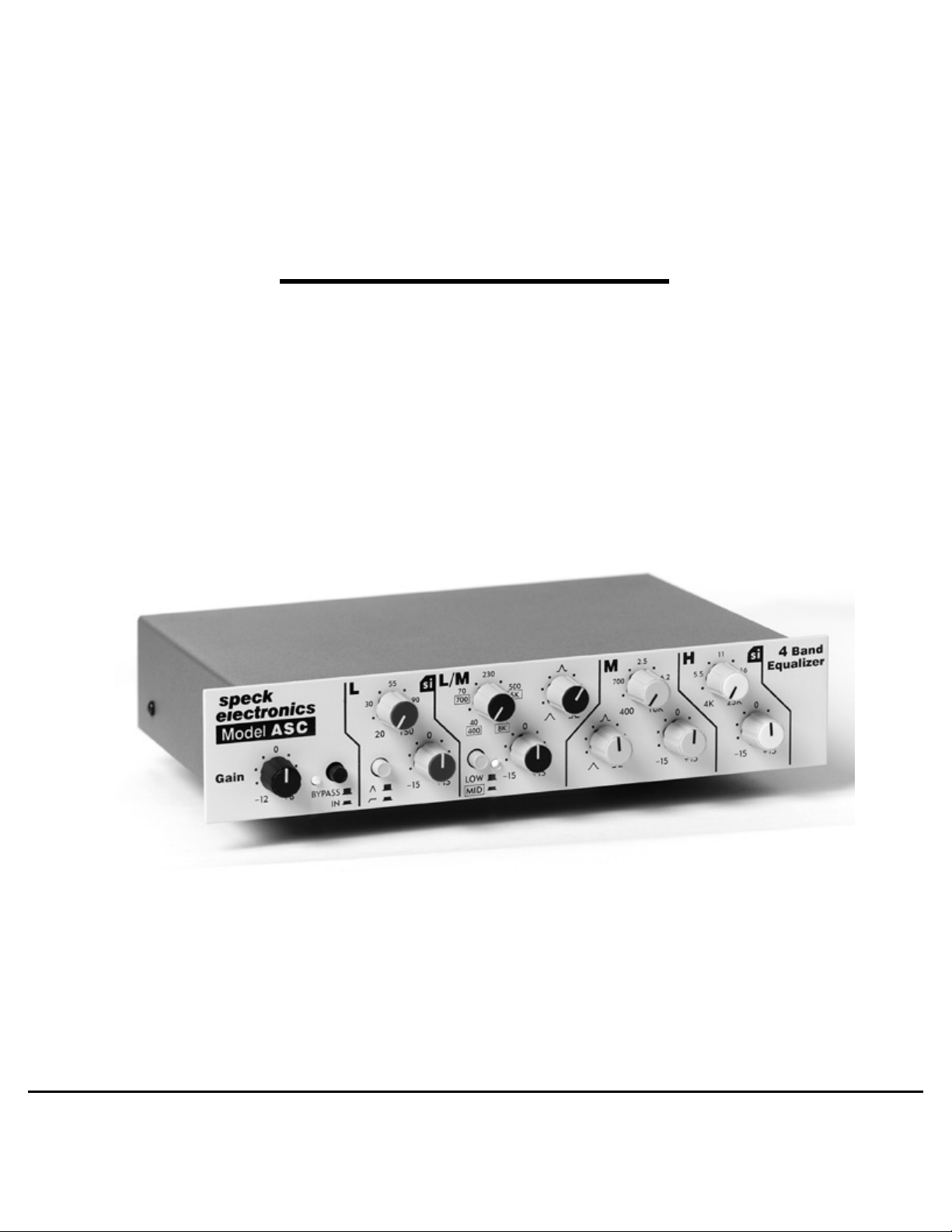
Model ASC
4 BAND PARAMETRIC EQUALIZER
Reference Manual
speck
electronics
Page 2

Warranty
Notice
Edition
Speck Electronics products are warranted to the original owner to be free of
defects in material or workmanship.
This warranty does not apply to any product subject to accident, misuse, neglect
or failure to comply with normal maintenance procedures or if the serial
number has been defaced, altered, or removed; nor will Speck Electronics
accept responsibility for damages resulting from improper installation,
alteration or unauthorized parts or repairs. If the product is modified by the
customer without permission, the customer agrees to pay for parts and labor
necessary to remove the modification before repair. The cause of the defect is
in the sole judgment of Speck Electronics.
Should a defect develop within one year of purchase from Speck Electronics or
an authorized dealer, Speck Electronics will supply the part or parts necessary
at no charge. Labor is covered in this warranty for a period of one year.
Outside service, repairs or pickups are not covered under this warranty.
Any item returned for warranty repair should be sent, if possible, in the original
packing container, prepaid to Speck Electronics, 341 E. Alvarado Street,
Fallbrook, California, 92028. If in our opinion the packing container is
improper for return shipping, we reserve the right to supply a new container
at a minimal charge.
In the interest of improving Speck products; designs and specifications are
subject to change without notice. It should be mentioned that if a change is
necessary for any reason, we make every effort to document
that change and send an "update notice" to all customers at no charge.
Speck Electronics makes no warranty of any kind with regard to this material,
including, but not limited to, the implied warranties of merchantability and
fitness for a particular purpose. Speck Electronics shall not be liable for errors
contained herein or for incidental consequential damages in connection with the
furnishing, performance, or use of this material.
This document contains proprietary information which is protected by
copyright. All rights are reserved. No part of this document may be
photocopied, reproduced, or translated into another language without the prior
written consent of Speck Electronics.
The information contained in this document is subject to change without notice.
All trademarks are the property of their respective owners.
First Printing - October 2000
Page 3

Contents
iii
Chapter 1 Introduction
Chapter 2 Installation
Chapter 3 Operation
General ......................................................................................
Standard Accessories .................................................................
Model PS-4 power module ..................................................
Hardware..............................................................................
Operator Safety Summary .........................................................
Power source .......................................................................
Grounding the product ........................................................
Using the proper power module ..........................................
Removing the cover ............................................................
Specifications ............................................................................
General ................................................................................
Unpacking and inspection ...................................................
Environmental considerations .............................................
Electrical grounding safety .................................................
Mechanical Installation .............................................................
Connecting the power module ............................................
Power module mounting location .......................................
Fuse replacement ................................................................
Physical Placement of Adjacent Equipment ..............................
Default Control Settings ............................................................
Cleaning ....................................................................................
Repacking for Shipment ............................................................
Interfacing to the Model ASC ...................................................
The Input connectors ...........................................................
The Output connectors ........................................................
Transformer option .............................................................
Connecting the ASC to mixer inserts ........................................
General.................................................................................
Basic Theory of Equalizers.........................................................
Low-pass filter......................................................................
High-pass filter .....................................................................
Bandpass filter......................................................................
Front Panel Controls
...............................................................
2
3
3
3
3
3
3
3
3
4
5
5
5
5
6
6
6
7
7
7
8
8
8
9
9
9
10
11
11
11
11
11
Page 4

Chapter 3 Operation (continued)
iv
Chapter 4 Wiringand Other
Gain Control .........................................................................
Bypass Switch......................................................................
Power/Bypass LED..............................................................
L - Low Band Controls ........................................................
L/M - Low/Mid Band Controls............................................
M - Mid Band Controls........................................................
H - High Band Controls .......................................................
Rear Panel
Input Connectors ..................................................................
Output Connectors ..............................................................
Ground Lift Switch .............................................................
Transformer Option .............................................................
Power Supply Connector ....................................................
Wire Tie Holder ..................................................................
Chassis Ground ...................................................................
Aux DC I/O .........................................................................
General ................................................................................
Start simple .........................................................................
Audio Cable ...............................................................................
Connectors ..........................................................................
AC Distribution and Safety .......................................................
Proper AC Grounding .........................................................
Quality AC system ..............................................................
AC distribution ....................................................................
Clock noise and AC ............................................................
Safety earth connection .......................................................
Electronics earth ..................................................................
Proper Audio Grounding and Shielding ....................................
EMI and RFI ..............................................................................
Sources of EMI ...................................................................
Reducing EMI .....................................................................
................................................................................
12
12
12
12
12
13
15
15
17
17
17
17
18
18
18
19
19
20
20
20
21
21
21
21
21
22
22
22
22
23
23
23
Page 5
1 Chapter 1 Introduction Section
speck
electronics
Model
Gain
ASC
0
_
+
6
12
speck
electronics
Fallbrook, C alifornia
POWER AUX DC I /O
L
30
BY PA SS
IN
Mod el ASC - 4 Band Equ al i ze r
S/N
OUTPU T TRANS FORMER OPTI ON
70
700
40
400
LO W
MID
230
800
2.5
500
5K
8K
0
_
+
15
15
M
700
10K
6.2
0
_
15
H
+
11
si
4
Band
5.5
4K
25K400
15
16
_
15
Equalizer
0
+
15
55
20
150
L/M
si
90
0
_
+
15
15
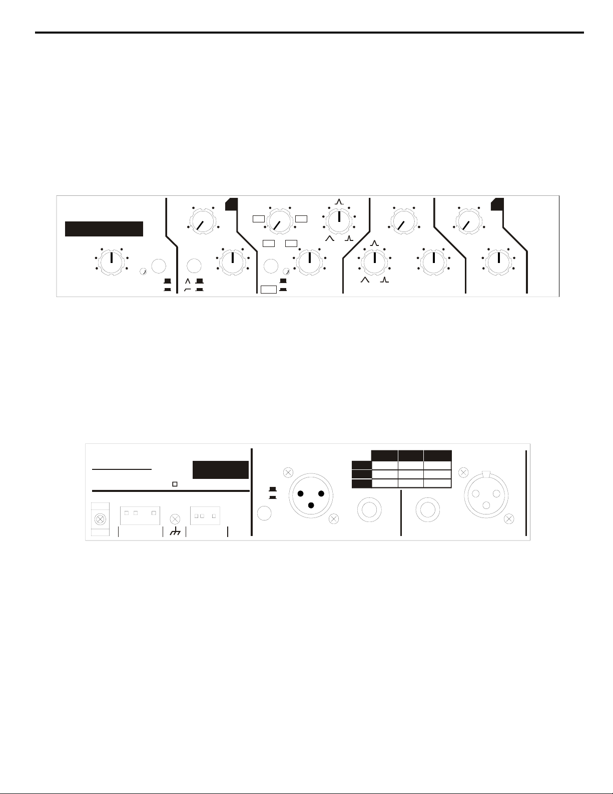
Figure 1a. Front Panel Layout
OUTPUT
GND
LIFT
BAL. XLR BAL. ¼UNBAL .
HIGH
PIN 2
LOW
PIN 3
PIN 1
GND
TIP
RING
SLEEVE
TIP
SLEEVE
¼
INPUT
USE WIT H PS-4
POWER MODULE
USE WITH SPECK
PRODUCTS ONLY
Figure 1b. Rear Panel Layout
Page 6

Chapter 1 Introduction Section
Introduction
2
General
Thank you for purchasing our Model ASC Equalizer. The Model ASC
has operational features that are easy to understand and you should be
up and running in no time. If you are unfamiliar with audio equipment
or audio signal flow, it is recommended that you read this manual. If
you have any questions regarding the Model ASC or any Speck product,
do not hesitate to contact Speck Electronics. Our phone number is
+760-723-4281.
The Model ASC is a four band parametric equalizer that is housed in a
1/2 rack space chassis. It is well suited in audio applications from
professional recording, sound contracting, touring, or any application
where equalization is required.
The Model ASC is available in four models:
ASC-NA
ASC-EU
ASC-T-NA
ASC-T-EU
The standard Model ASC
(North American Power supply)
The standard Model ASC
(European Power supply)
The Model ASC with output transformer option
(North American Power supply)
The Model ASC with output transformer option
(European Power supply)
One of the unique features of the Model ASC is that it integrates two
types of filter circuit design. The Low and High bands use a simulated
inductor (SI) circuit design, and the Low/Mid and Mid bands are of a
state-variable filter design.
The Model ASC is divided into 4 bands that cover a total frequency
range of 20Hz to 25kHz:
L - The Low frequency band (Simulated inductor)
L/M - a selectable Low or Mid frequency band (State variable filter)
M - the Mid frequency band (State variable filter)
H - the High frequency band (Simulated inductor)
The Model ASC with its balanced input and output will accept a wide
variety of signal levels and has been designed with a generous amount
of headroom.
The Model ASC is shipped with an external 16 VAC, 1.1 amp power
Page 7

Chapter 1 Introduction Section
Standard
Accessories
3
Model PS-4 power module
Operator Safety
Summary
Operator Safety
Summary
Power source
Grounding the product
Use the proper
power module
Do not remove
covers or panels
Hardware
IMPORTANT!
module. The power module has a 6' two conductor cable and is fitted
with a special 4 pin Molex connector for mating to the “Power” input on
the rear of the ASC. All AC rectification, filtering, and DC regulation is
performed within the chassis of the Model ASC.
The PS-4 power module is available in 2 versions; a North American
version and European version. The North American version is designed
to operate with 120 VAC power and the European version is designed to
operate with 220, 230 or 240 VAC power.
(4) rubber bumpers are supplied when used for table top mounting, (2)
6-32 x 1/2” machine screws are supplied to mount the ASC to an
optional rack shelf, and a nylon wire to secure the power supply cable to
the nylon holder adjacent to the power supply connector.
The external power module is intended to operate from an AC power
source that does not apply more than 120 Volts RMS (North American
Version) or 240 Volts RMS (European Version) between the supply
conductors.
To avoid electrical shock, plug the power module into a properly wired
receptacle before making any audio connection to the ASC. A
protective ground connection, by way of the ground terminal on the rear
panel of the ASC, is essential for safe operation.
Use only the PS-4 power module, cable, and connector that is supplied
with your Model ASC. Using any other power module or power supply
will most definitely damage the Model ASC.
USE ONLY THE POWER MODULE THAT IS SPECIFIED
FOR YOUR PRODUCT.
To avoid personal injury, do not remove the top cover of the Model
ASC. Never operate the Model ASC or power module without the cover
panel properly installed. If it becomes necessary to remove the cover
panel of the Model ASC for service, always unplug the AC power and
disconnect the power cable before proceeding.
The power module is a “Class 2 transformer” device and can only be
used indoors. The ASC and power module should never be exposed to
rain or moisture.
Page 8

4 Chapter 1 Introduction Section
Specifications
Input Level
Output Level:
(Active Balanced)
(Transformer Balanced)
Input Impedance 20K Ohms
Output Impedance
(Active Balanced)
(Transformer Balanced)
Output Distortion(THD+n)
22Hz to 22KHz @ +24dBu
Frequency Response
Test Conditions:
AP balanced +4dBu signal connected to input.
Gain control set to “0” position.
All Boost/Cut controls set to “0”
Bypass switch set “In”
All other controls and switches “Don’t care”
AP analyzer connected at output
Normal
+4 dBu
Normal
+4 dBu
+4 dBu
Maximum
+24dbu
Maximum
+28dbu
+24dBu
120 Ohms
600 Ohms
.0014%
Measured at active balanced output
Measured at transformer output
Residual Noise Measurement
Test Conditions:
AP balanced signal connected to input.
AP Generator set “Off”
Gain control set to “0” position.
All Boost/Cut controls set to “0”
Bypass switch set “In”
All other controls and switches “Don’t care”
AP analyzer connected at output
Residual Noise Measurement
(22Hz-22kHz)
(10Hz-80kHz)
Power requirements (Power Module) 16 VAC, 1.1 Amp
Dimensions HxWxD = 1.75" x 8.5" x 7.25"
5Hz(-0.5dB) to 103kHz(-0.5dB)
2Hz(-3dB) to 154kHz(-3dB)
10Hz(-0.5dB) to 110kHz(-0.5dB)
10Hz(-3dB) to 154kHz(-3dB)
-93 dBu
-87 dBu
(45mm x 216mm x 190mm)
Shipping weight Approximately 5 lbs (2.27Kg)
ALL MEASUREMENTS WERE PERFORMED WITH AN AUDIO PRECISION SYSTEM ONE TEST SET.
Page 9

Chapter 2 Installation Section
Installation
5
General
Unpacking and Inspection
Environmental
Considerations
Electrical
Grounding Safety
The following information should give you the basics on how to install
the Model ASC and PS-4 power module. The proper installation of the
Model ASC as part of a larger system requires a clear understanding of
audio wiring, AC distribution, grounding, and shielding techniques.
When the Model ASC is being installed into a larger system it may be
necessary to retain the services of someone experienced in these matters.
The Model ASC is delivered in a special, protective container and was
carefully inspected both mechanically and electrically before shipment.
It should be physically free of mars and scratches and in perfect
electrical order upon receipt. To confirm this, the product should be
inspected for physical damage that may have occurred in transit. Any
damage should be reported to your delivery company as soon as
possible.
The Model ASC will operate satisfactorily over a wide range of ambient
temperatures. The Model ASC will operate from 10 to 50 degrees C and
the external power module will operate from 0 to 30 degrees C. If
installed in an equipment rack that also contains heat producing
equipment, adequate ventilation should be provided. This will prolong
component life and maximize operational stability.
While the internal circuitry of the ASC is fully shielded by the steel
chassis, installation should nevertheless be planned to avoid locating it
or any low level audio equipment immediately adjacent to power
amplifiers, power supplies, or any source of low frequency
electromagnetic emissions.
To protect operating personnel, the National Electrical Manufacturers
Association (NEMA) recommends that the instrument panel and rack
cabinet be grounded.
Merely affixing the Model ASC into an equipment rack is no guarantee
that the product is making a reliable ground connection. The mounting
rails in the equipment rack should never be depended upon for a ground
connection.
Upon loss of the protective ground connection, all accessible conductive
parts, including knobs and controls that may appear to be insulating, can
render an electric shock.
Page 10

Chapter 2 Installation Section
Mechanical
Installation
Connecting the
power module
Power Module
Mounting location
6
Because the power module uses a 2 bladed AC plug, audio signal
grounds and DC common at the Model ASC are isolated from the
AC safety earth. The chassis of the ASC can be connected to earth
by way of the chassis ground terminal on the rear panel.
The location of the Model ASC should be such that the operator has a
clear, unobstructed view of the front panel from his/her normal
operating position. The unit should also be within easy reach of the
operators normal position in order to facilitate the use of the front panel
controls
The 1/2 rack form factor of the ASC allows a single unit to be mounted
on a table top with the (4) rubber bumpers supplied with the unit,
multiple units stacked, or two units mounted side-by-side on a 1U rack
shelf manufactured by Middle Atlantic Products (Model UTR1).
When attaching the ASC to the rack shelf, it should be secured with the
(2) 6-32 x 1/2” machine screws supplied with the unit. Do not use
screws that are longer than 1/2” in length as they could damage the
internal circuit board. When the ASC or multiple ASC’s are mounted to
the rack shelf, they may be installed into any 19" wide equipment rack
that uses standard E.I.A. universal spacing.
In order to provide power to the Model ASC, it is necessary to connect
the 4 pin rectangular plug of the power module to the rear panel. Before
connecting the 4 pin rectangular plug to the ASC, make certain the
power module is not
connected to an AC receptacle.
To connect the power supply, fit the rectangular white Molex plug from
the power supply cable into the rectangular shaped opening on the rear
panel that is labeled “Power” (not
“Aux DC I/O”). The respective
connectors are keyed so the plug and its receptacle can fit in only one
direction. Push the plug into the header until it stops.
After the power module plug has been connected, place the power
supply cable over the nylon wire tie holder to the left of the hole and
secure with the wire tie that has been included.
One of the primary reasons that the PS-4 power module is external is to
insure that its power transformer maintains a safe distance from the
active electronics of the Model ASC. It is recommended that the power
module be located at a reasonable distance from the ASC, mixers, and
audio cables.
Page 11

Chapter 2 Installation Section
Fuse replacement
7
The power module normally generates a small amount of heat during
operation. It is important that adequate ventilation is provided when
planning the mounting location.
The external power module does not provide an AC power switch. It is
recommended the power module be plugged into an AC power strip that
uses a power switch.
The PS-4 power module has an internal “one shot” thermal fuse. Fuse
replacement is not possible with this module.
If it has been determined that the power module has failed, contact
Speck Electronics for a factory replacement at +760-723-4281.
Physical Placement of
Adjacent Equipment
Default Control
Settings
Any device that emits a high EMI (Electro Magnetic Interference) or
RFI (Radio Frequency Interference) energy field should be treated with
suspicion. EMI is considered any unwanted signal which adversely
affects the operation of the Model ASC or the audio system. This
subject is discussed in Chapter 4.
Electronic equipment such as power amplifiers, power supplies
(including the PS-4 wall mount type), video monitors, computers,
certain synths and samplers must be located away from the Model ASC
and its associated audio cables. It may be necessary to alter the
positions of certain equipment that you feel would cause buzzes or hums
in the audio system.
Before any attempt is made to operate the Model ASC, it would be a
good idea to set all the controls to their neutral positions. This gives you
a reference point to work from when adjusting controls and switches.
All “Frequency Sweep” controls should be set to their full counterclockwise setting. All “Boost/Cut” controls should be set to their “0”
center detented position. The “bypass”switch should be set to the "In"
position, the “Low/Mid” and “Peak/Shelf” switches set out, and the
“Gain” control set to its “0” center detent position.
When any future reference is made to the controls or switches of the
ASC, is will be assumed that they have been set to their neutral
positions.
Page 12

Chapter 2 Installation Section
Cleaning
Repacking For Shipment
Interfacing to the
Model ASC
8
The front and rear panels are a high quality painted surface and the panel
lettering is applied using a silkscreen printing technique.
To clean the front or rear panel, wipe the surface gently using a soft lintfree cloth to avoid scratching the panel or markings. Paper towels are
not recommended. Commercially available window cleaner solutions
may be used; however, the solution should be applied to the cloth and
not the panel to avoid the seepage of liquid to the inside of the
enclosure.
The following information is provided as a general guide for
repackaging your Model ASC for shipment. If you have any questions,
contact Speck Electronics at +760-723-4281.
If the product is to be shipped to Speck Electronics for service or repair,
attach a tag to the product identifying the owner and indicating the
service or repair to be accomplished. Include the model number and
serial number of the product. Place the product in the original container
if available. If the original container in not available, a suitable one can
be purchased from Speck Electronics.
If the original container is not used, wrap the product in heavy plastic
before placing in an inner container. Use plenty of packing material
around all sides of the product and protect panel faces with cardboard
strips. Mark shipping container with "Delicate Instrument" or "Fragile",
and insure the shipment for the proper amount.
Note: Speck Electronics cannot be responsible for equipment that
arrives damaged or uninsured.
The ASC is a very flexible product and there are many places it may be
interfaced - too many to enumerate in the manual. Virtually any line
level signal may be connected to the inputs and outputs of the Model
ASC; Synths and samplers, mixing consoles (patch points, line inputs/
outputs effects sends/returns), multitrack DAT recorders, hard disk
recorders, analog tape recorders, cassette recorders, CD players, and
external mike preamps.
A basic rule to follow is that inputs always connect to outputs, and
outputs always connect to inputs. This rule applies regardless of the
type or brand of product that is interfaced to the ASC. Each
manufacturer may have their own recommendation for interfacing to
external equipment.
Page 13
Chapter 2 Installation Section
9
The Input
The Output
Transformer Option
(for Model ASC-T only)
OUTPUT
GND
LIFT
BAL. XLR BAL. ¼UNBAL .
HIGH
PIN 2
PIN 3
LOW
PIN 1
GND
TIP
RING
SLEEVE
TIP
SLEEVE
¼
INPUT
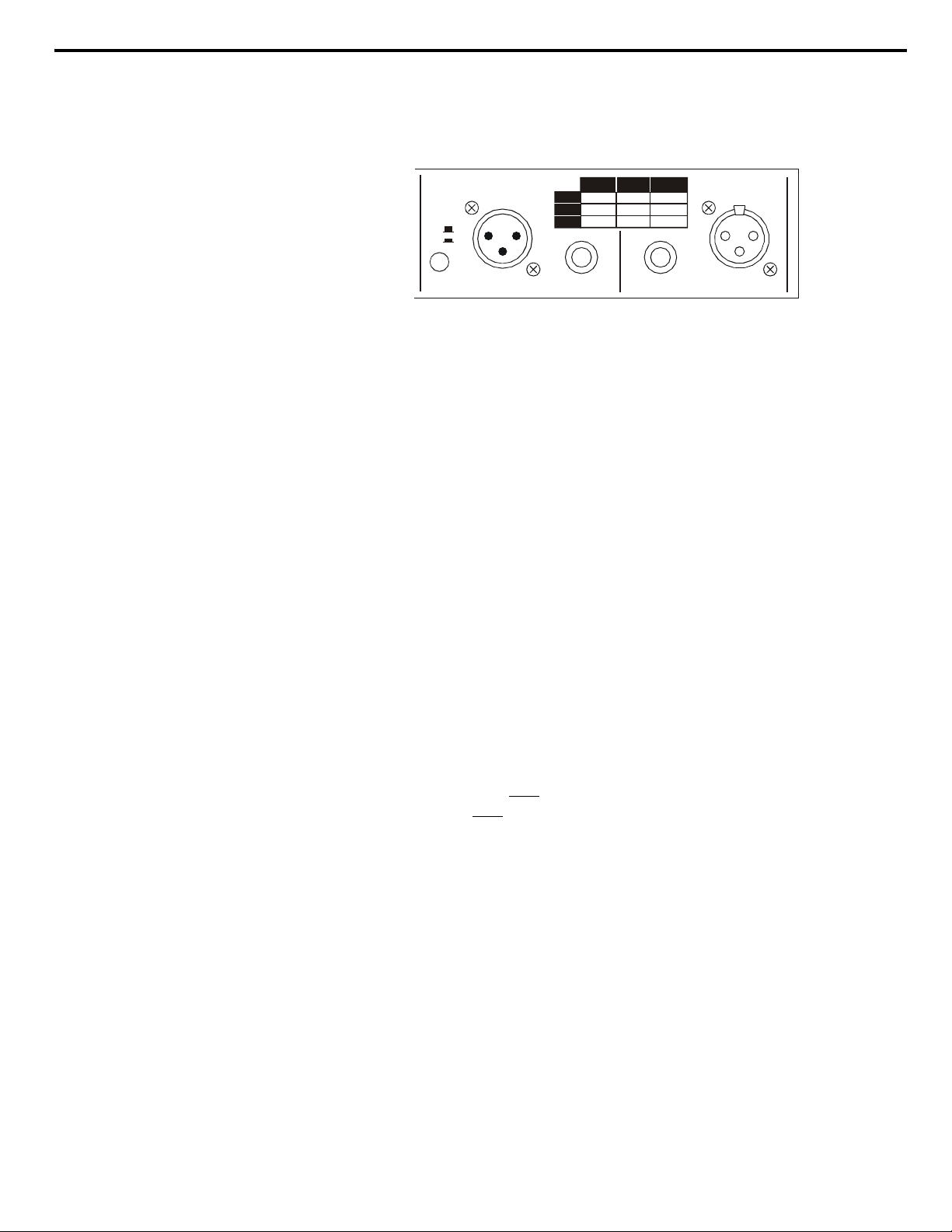
Figure 2. Input & Output Connectors
The input of the ASC has a balanced 1/4” jack and a balanced XLR
connector (Figure 2). These inputs are internally wired in parallel and
there is no operational difference between one or the other. The two
inputs can not be used simultaneously. The 1/4” input jack will accept a
1/4” TRS plug for balanced operation, or a 1/4” mono plug for
unbalanced operation.
The output of the ASC has a balanced 1/4” jack and a balanced XLR
connector (Figure 2). These inputs are internally wired in parallel and
there is no operational difference between one or the other except on the
Model ASC-T (see below).
A legend is provided on the rear panel to be used as a guide for the
proper configuration of input and output connectors.
The ASC with the optional output transformer gives you two choices of
balanced outputs; electronic active balanced at the 1/4” TRS jack or
transformer balanced at the XLR connector. On the Model ASC-T, the
transformer is wired only
output is wired only
to the XL connector and the balanced active
to the to the 1/4” TRS jack.
To prevent the transformer from loading the electronic active output
circuit, the XL output is automatically disabled when the 1/4” TRS
output jack is used on the ASC-T version.
Page 14
Chapter 2 Installation Section
Connecting the
Model ASC to inserts
10
When connecting to an audio mixer, you may choose to connect the
ASC to the insert points of the input channel. A mixer’s insert point
(access point) exist exclusively for the access of devices such as the
Model ASC, limiters, compressors, gates, etc. These aforementioned
devices are regarded as “processing” equipment and are normally
connected (inserted) into a single channel. Processing equipment differs
from “effects” devices in that effects such as reverb and delay are
connected into the send/return jacks and may be accessed from all
channels via the effects (aux) send controls and blended to the main
groups with the effects (aux) returns controls.
Some larger recording consoles that lack a patchbay may use two jacks
for the channel's insert points; one jack for insert output, and another for
the insert input. Although, many mixers have a stereo (TRS) jack for
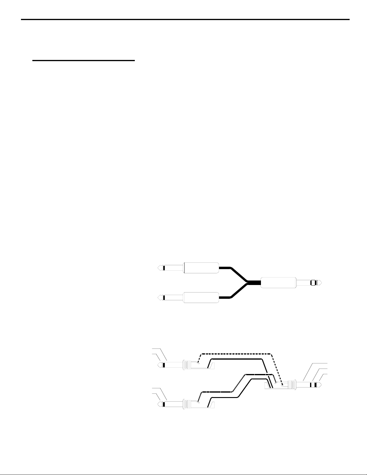
the insert points. For these mixers it will be necessary to utilize a
special "Y" cable with a stereo plug at one end and two mono plugs at
the other ends. (See figure 3)
When patch points are not available, such is the case with many smaller
mixers, the source signal (recorder or sampler) may be connected
directly to the inputs of the Model ASC. The outputs of the Model ASC
would then be connected to the line inputs of the mixer.
TO MODEL ASC INPUT
TO MODEL ASC OUTPUT
SLEEVE
TIP
MONO TS PLUG
SLEEVE
TIP
MONO TS PLUG
TO MIXERS INPUT JACK
Figure 3a. “Y” Cable
SLEEVE
RING
TIP
STEREO TRS PLUG
Figure 3b. “Y” Cable Schemtic
Page 15

Chapter 3 Operation Section
Operation
11
Basic Theory
of Equalizers
General
Low-pass filter
High-pass filter
Bandpass filter
We hope to give you basic information on the operation of the Model ASC
and adequately describe its controls, switches, and connectors.
The information in this manual is intended to help with the technical
process when using your Model ASC. Words alone could not adequately
describe how to adjust the controls on the Model ASC. Your ears should
be your best gauge of how to adjust the equalizer controls to make the
sound fit your requirements.
A parametric equalizer falls into the generic category called a “filter”. A
filter is an electronics circuit that allows signals of certain frequencies to be
transmitted through a system, while preventing the transmission of other
frequency ranges.
There are 3 basic types of passive or active filters; low-pass, high-pass and
bandpass.
A low-pass filter is a circuit that passes all low frequency signals and
rejects high frequency signals. The crossover point that low frequencies
pass through can be either fixed at a specific point or variable.
A high-pass filter is a circuit that passes all high frequency signals and
rejects low frequency signals. The crossover point that high frequencies
pass through can be either fixed at a specific point or variable.
A bandpass filter is a circuit that will pass only a fixed frequency band and
reject signals above and below the selected band.
A parametric equalizer is a very elaborate bandpass filter that offers the
ability to control the filter's basic parameters - hence the term "Parametric
Equalizer". These controllable parameters are the bandpass center
frequency, the amplitude of the bandpass frequency, and the width of the
bandpass frequency. These previously mentioned parameters as found on
audio parametric equalizers are commonly known as the sweep control,
boost/cut control, and bandwidth (Q) adjust respectively.
The Model ASC utilizes all the previously mentioned parametric controls.
Page 16
Chapter 3 Operation Section
0
0
6
+
BY PA SS
IN
Gain
speck
p
p
electronics
ASC
Model
12
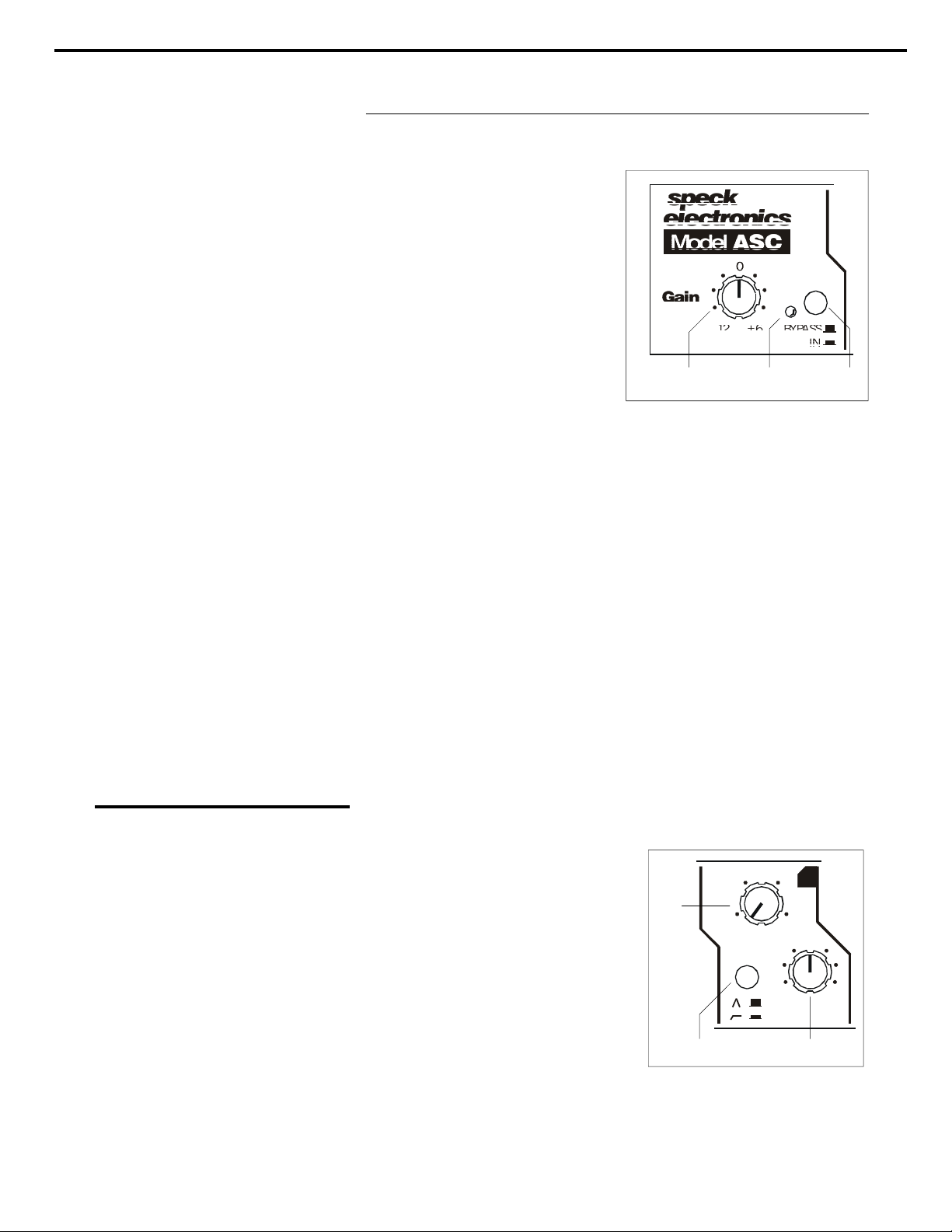
FRONT PANEL CONTROLS
12
2. Equalizer bypass switch
3. Power/Bypass LED
L (LOW) BAND
4. Low frequency sweep
1. Gain Control
This control is used to adjust the
input sensitivity between -12dB and
+6dB relative to the level that is
present at the input connector. The
center detented position is “0” unity
gain. Under normal operation with
a balanced input and balanced
output, this control can be set to the
_
“0” position. In cases when the
ASC is interfaced to an unbalanced
device, a 6dB loss may occur. The
1 3 2
gain control can be set to +6dB to
compensate for this loss of signal.
This switch is used to enable or disable the equalization circuit. In the
“out” position all equalizer bands are bypassed. When in the bypass
position, the active balanced input stage, the gain control, the active
balanced output stage, and the optional transformer remains operational.
This allows the levels to match when comparing the equalized signal to
the unequalized signal, even when the gain control has been set higher
or lower than 0 db.
When this switch is depressed, the equalizer is enabled.
This dual colored LED will illuminate red indicating that the ASC is
powered and active. It also indicates that the equalizer is in the “bypass”
mode. When the switch is depressed, this LED will change from red to
green indicating that the equalizer is enabled.
The low frequency sweep control is used in conjunction with the low
boost/cut control and provides
continuous adjustment of the center
frequency from 20Hz (fully
counterclockwise) to 150Hz (fully
clockwise).
L
4
55
si
30
20
150
90
0
Bandwidth (Q)
The bandwidth for the selected
frequency of the low band is
_
+
15
automatically adjusted with the
selection of the frequency sweep
5 6
control. The 20Hz setting on the
sweep control will result in a narrow
bandwidth of approximately .25
octave (Q=4).
As the frequency sweep control is adjusted to its highest setting
(150Hz), the bandwidth widens to approximately 1.6 octaves (Q=.6).
15
Page 17
Chapter 3 Operation Section
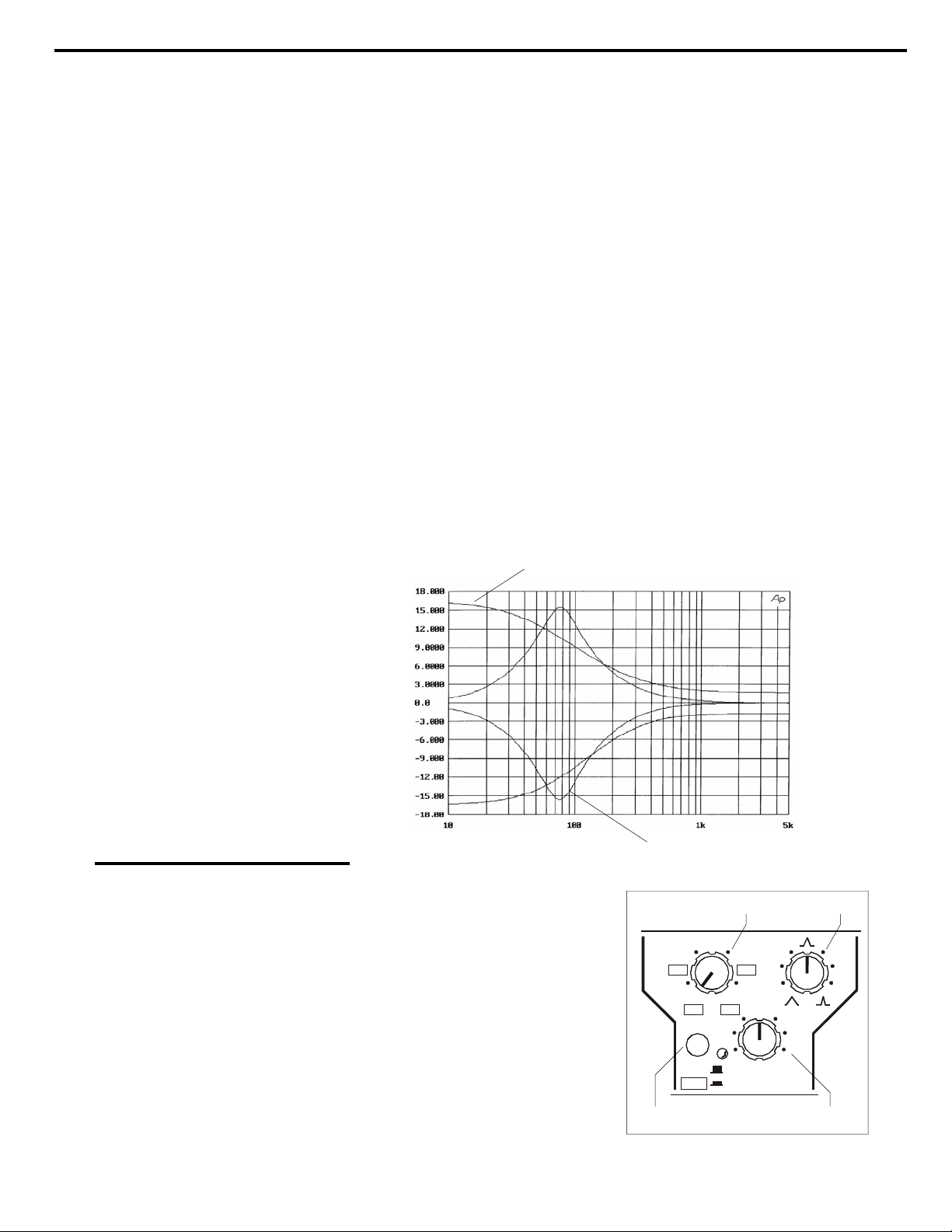
5. Low boost/cut
6. Peak/Shelf Switch
L/M (Low/Mid) BAND
7. Low/Mid select switch
13
The boost/cut control provides a reciprocal volume adjustment of the
selected frequency control. This means that whatever frequency is
"boosted" with the boost/cut adjusted from its center position clockwise,
an identical but opposite result is achieved when that same frequency
selection is "cut" from its center position counterclockwise. Once the
desired frequency has been selected with the low frequency sweep
control, that frequency may be continuously accentuated or attenuated
(boost or cut) from 0 to +15dB or -15dB. 0dB (flat) is obtained when
this control is set to its center detented position.
This switch changes the low frequency band from a peak/dip curve (as
shown in Figure 4a) to shelving curve (as shown in Figure 4b).
Fig. 4a. Shelving Curve
This switch selects the frequency
range of the Low/Mid band. In the
“out” position, the low range of
40Hz-800Hz is selected. When
depressed, this switch selects the
mid band of 400Hz-8kHz.
A yellow LED to the right of this
switch illuminates indicating that
the mid band has been selected.
Fig. 4a. Peak/Dip Curve
70
700
40
400
LO W
MID
230
800
8K
_
15
L/M
500
5K
8
10
0
+
15
7
9
Page 18

Chapter 3 Operation Section
14
8. Low/Mid frequency sweep
9. Low/Mid Boost and cut
10. Low/Mid bandwidth adjust
The low/mid frequency sweep control is used in conjunction with its
respective boost/cut control and provides continuous adjustment of the
center frequency from 40Hz (fully counterclockwise) to 800Hz (fully
clockwise) for the low range selection or 400Hz (fully
counterclockwise) to 8kHz (fully clockwise) for the mid range selection.
This control provides 15dB of bell shaped boost or cut for the low/mid
band frequency range, and is used in conjunction with the low/mid
frequency sweep adjust. 0dB (flat) is obtained when this control is set to
its center detented position.
For the low/mid band, a continuously adjustable bandwidth control is
provided. This control sets the width of the frequency that has been
selected on the Low/Mid sweep control. When set fully CCW, the
bandwidth is a wide 2 octaves (Q=.5). When set fully CW, the
bandwidth narrows to .25 octave (Q=3.8). The center position is
approximately .6 octaves (Q=1.6).
In addition to the ability to contour low band audio, the low frequency
controls may be used to reduce or eliminate low frequency hum or buzz.
Low hum is typically 60Hz, whereas buzz is typically 120Hz and
240Hz. If there is a hum or buzz on an audio track, the low sweep
control and associated boost/cut control can be used to remove this.
To reduce 60Hz hum, start by setting the bandwidth control to its fully
(CW) position, the low frequency sweep control to its fully
counterclockwise (CCW) position; this is about 40Hz. Turn the Boost/
Cut control fully CCW. Return to the frequency sweep control, and
turn clockwise a little until the 60Hz hum has been reduced. This
setting is the 60Hz point. Now go back to the Boost/Cut control and
adjust as necessary.
In some extreme cases, it may be necessary to use the Low band and the
Low/Mid band of equalization in order to remove the undesirable affects
of 60Hz or 120Hz hum.
Page 19
Chapter 3 Operation Section
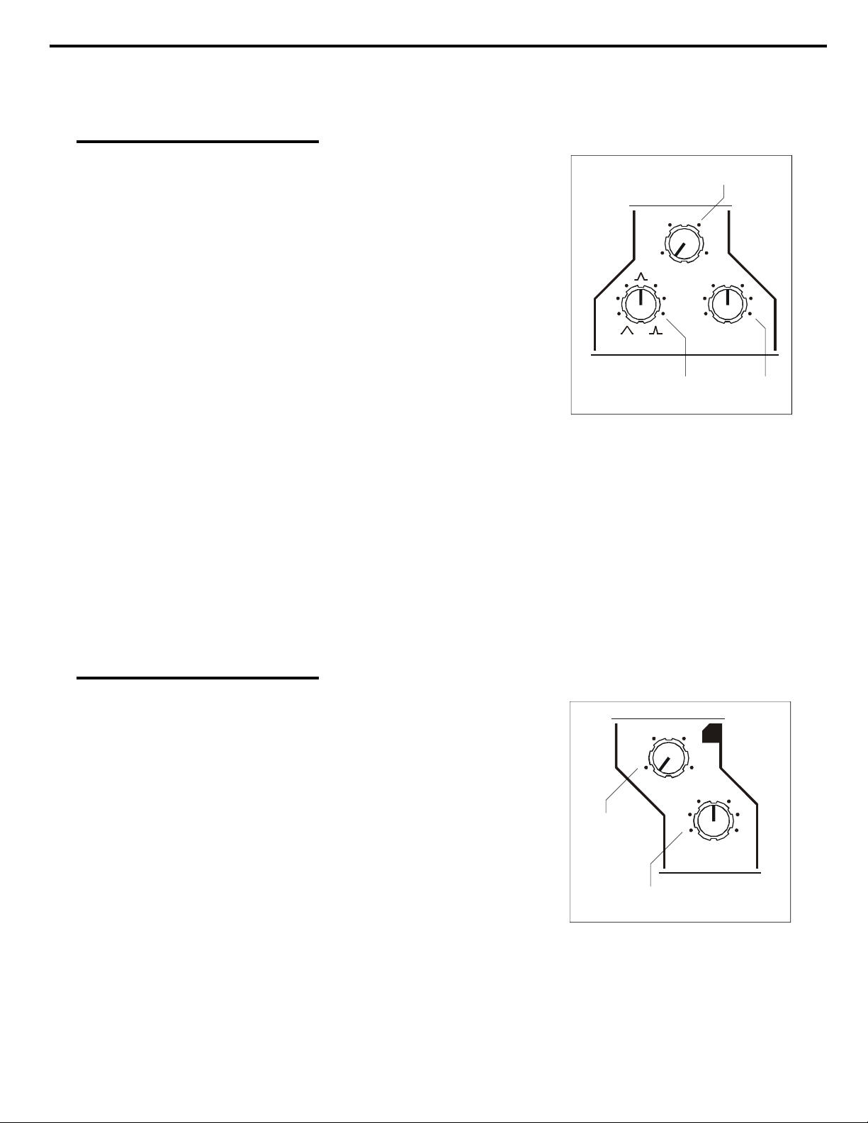
M (Mid) BAND
15
11. Mid frequency sweep
12. Mid boost/cut
13. Mid bandwidth adjust
H (High) BAND
14. High frequency sweep
The mid frequency sweep control
is used in conjunction with the
11
mid boost/cut control and
provides continuous adjustment of
the center frequency from 400Hz
M
700
2.5
6.2
(fully counterclockwise) to
400
10KHz (fully clockwise).
10K
0
This control provides 15dB of bell
shaped boost or cut for the mid
_
+
15
15
band (400Hz to 10kHz) frequency
range, and is used in conjunction
with the high frequency sweep
13
12
adjust. 0dB (flat) is obtained
when this control is set to its
center detented position.
For the mid band, a continuously adjustable bandwidth control is
provided. This control sets the width of the frequency that has been
selected on the Mid sweep control. When set fully CCW, the bandwidth
is a wide 2 octaves (Q=.5). When set fully CW, the bandwidth narrows
to .25 octave (Q=3.8). The center position is approximately .6 octaves
(Q=1.6).
The high frequency sweep control is used in conjunction with the high
boost/cut control and provides
continuous adjustment of the
center frequency from 4kHz
(fully counterclockwise) to 25kHz
H
5.5
11
si
16
(fully clockwise).
4K
Bandwidth (Q)
The bandwidth for the selected
frequency of the high band is
14
25K
0
_
+
15
15
automatically adjusted with the
selection of the frequency sweep
control. The 4kHz setting on the
15
sweep control will result in a
narrow bandwidth of
approximately .5 octave (Q=1.8). As the frequency sweep control is
adjusted to its highest setting (25kHz), the bandwidth widens to
approximately 1.8 octaves (Q=.6).
This control provides 15dB of bell shaped boost or cut for the high
Page 20

Chapter 3 Operation Section
16
15. High boost/cut
frequency range (4kHz to 25kHz), and is used in conjunction with the
high frequency sweep adjust. 0dB (flat) is obtained when this control
is set to its center detented position.
In addition to the ability to contour high band audio, the high band
controls can reduce hiss that is present on low frequency information.
If there is high frequency hiss or digital noise on a kick drum or bass
track, the high sweep control may be set to its higher clockwise setting
(16kHz-25kHz) and its associated boost/cut control "cut" a few dB's.
As long as you don't dramatically change the sound of the low
frequency audio, this could remove a little noise. Every little bit
improves the overall quality of your sound.
Page 21
Chapter 3 Operation Section
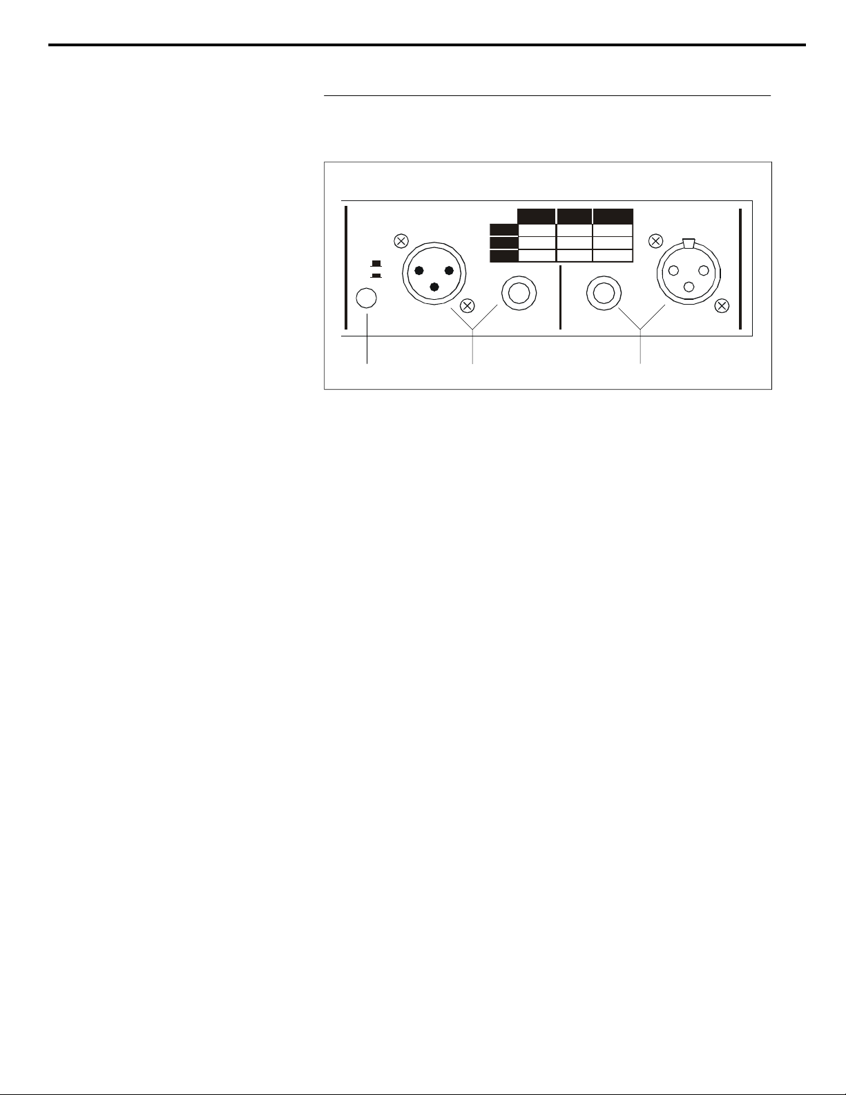
REAR PANEL
17
16. Input Connectors
17. Output Connectors
18. Ground lift Switch
OUTPUT
GND
LIFT
BAL. XLR BAL. ¼UNBAL .
HI GH
PIN 2
PIN 3
PIN 1
TIP
RING
SLEEVE
LOW
GND
17 18
TIP
SLEEVE
¼
INPUT
16
Two types of input connectors are available on the ASC; a standard 1/4"
TRS balanced jack and a female XLR connector. These inputs are
internally wired in parallel and identical in every aspect except for the
connector.
The 1/4” jack will accept a balanced TRS plug or a mono TS unbalanced
plug. For unbalanced operation a standard mono plug should be used. A
legend on the rear panel can be used as a guide for the proper
configuration of input and output connectors.
Two types of output connectors are available on the ASC; a standard 1/4"
TRS balanced jack and a male XLR connector. These connectors are
internally wired in parallel except on the transformer output version. (See
item 19 on the “Transformer Option”)
When depressed, this switch disconnects the ground of the ASC from pin
1 of the balanced XL output connector thereby inducing any piece of gear
interfaced to this connector to search out a ground path external to the
Model ASC. This can reduce the chance of ground loops and eliminate
unwanted hums or buzzes.
A few words about hums, buzzes, and the role of a ground lift.
Not to suggest that the reasons for hums in an audio system can’t be
explained…they can… but the explanation, cure, and costs are very often
out of the reach of the average project studio. This is why manufacturers
sometimes include a ground lift switch on their products. It just saves you
the trouble of clipping or soldering ground wires on your cables.
Page 22
Chapter 3 Operation Section
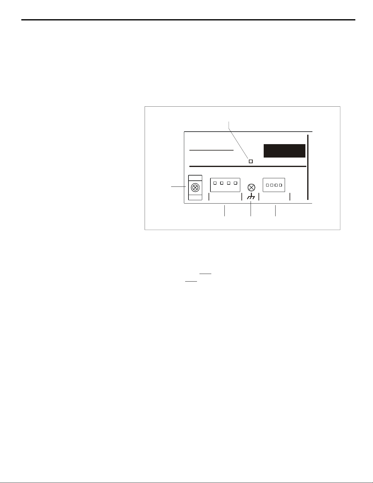
19. Transformer Option
(for Model ASC-T only)
20. Power Supply Connector
21. Wire Tie Holder
Hence, there is not a right or wrong position for a ground lift switch. If
either position improves an otherwise hummy-buzzy situation, that is the
right position.
19
speck
electronics
Fallbrook, California
POWER AUX DC I /O
Model ASC - 4 Band Equalizer
S/N
OUTPUT TRANS FORMER OPT ION
21
USE WIT H PS-4
POWER MODULE
USE WITH SPECK
PRODUCTS ONLY
20
22 23
The ASC with the optional transformer gives you two choices of
balanced outputs; electronic active balanced at the 1/4” TRS jack or
transformer balanced at the XL connector. On the Model ASC-T, the
transformer is wired only
output is wired only
to the XL connector and the balanced active
to the to the 1/4” TRS jack.
To prevent the transformer from interacting with the electronic active
output circuit, the XL output is automatically disabled when the 1/4”
TRS output jack is used on the ASC-T version.
This connector will accept the 4 pin rectangular plug of the power
module cable. This connector and respective plug are keyed so they will
fit in only one direction. For installation instructions refer to
"Connecting the Power Module" as described in Chapter 2.
For installations where the ASC is subject to extreme vibration or
movement, the wire tie holder may be used to secure the power cable.
18
Page 23

Chapter 3 Operation Section
19
22. Chassis Ground
23. Aux DC I/O
Because the ASC uses an external power module, the chassis is not
automatically earth grounded. If you experience hums or buzzes, this
screw may be used to connect the chassis of the ASC to known earth
such as an AC receptacle cover plate.
This connector is available to provide a source of dual regulated DC
voltage to an external device. This connector is reserved for future
Speck products.
Page 24

Chapter 4 Wiring and Other
Wiring and Other
Start simple
Audio Cable
Connectors
General
The following information is not specific to the operation of the Model
ASC, but rather general information regarding the “care and feeding” of
an audio system.
A general discussion about AC, AC grounding, audio grounding, EMI,
and quality wiring is discussed in this section. These subjects are very
often overlooked or misunderstood, and should be given consideration
when interfacing your equipment to any audio product.
A “quality” installation is essential when wiring any audio system.
When the time comes to actually interconnect your equipment, proceed
slowly. Interfacing the many pieces of electronic equipment to your
ASC and
audio system should be a logical, methodical process.
Start by connecting only your headphones or monitor power amp to the
mixer, and then add one line signal to the mixer at a time; carefully
listening and monitoring your progress. If a problem arises, such as a
buzz, hum, intermittent signal, or nonexistent signal, stop at that point
and solve the problem before proceeding.
Due to the high performance of the Model ASC, it is recommended that
you use only the highest quality audio cable. A high quality cable by
definition, is a cable that provides good mechanical strength, high
microphonic noise immunity, high frequency response, low crosstalk
and 100% shielding ability. All audio cable used with the Model ASC
should be a 3 conductor foil shield type (2 inner conductors and a shield
drain conductor). It is not recommended that the 2 conductor "off the
shelf cables" be used.
All wire and cable interfaced to the Model ASC should be terminated
with high quality connectors. A 1/4" plug or XL connector should make
a positive connection to its respective mating jack and provide adequate
strain relief to its cable. All connectors should also have a metal shell to
provide 100% shield for exposed conductors.
Feel free to check with Speck Electronics for recommendation when
selecting cable and connectors.
20
Page 25

Chapter 4 Wiring and Other
AC Distribution
and Safety
21
Proper AC grounding
Quality AC system
AC distribution
Clock noise and AC
Safety earth connection
When you are evaluating voltage and current requirements for your
audio system, it is important that your Model ASC equalizer and/or
audio system does not exceed the capacity of your AC service. You
should make certain that the earth (green) wire for the AC system makes
a reliable earth connection, and determine as best as possible that the AC
system is free of noise that could generate unwanted audible sounds or
cause problems in microprocessor based equipment.
When using a larger rack system it is recommended that a dedicated and
isolated AC service be provided. This service should have its own AC
wires, isolated receptacle, and breaker and not be shared with other
unrelated equipment.
Even with an isolated AC system, it may still be necessary to make use
of surge protectors, line filters, isolation transformers, or all of the
above. Power conditioners should be selected with care, since they
sometimes generate undesirable switching noises in audio systems.
When connecting many pieces of electronic equipment to an AC system
it is important that the AC is properly distributed. It is better to connect
all plugs to a common AC source than to have AC receptacles in
different locations.
When installing a large audio system, it may be necessary to consult a
qualified electrician that is familiar with the specialized style of
electrical wiring required for recording studios.
Clock noise is one of the greatest enemies of the audio racks AC system.
If a computer or any microprocessor based device (most samplers and
effects are) emits or somehow couples its clock signal with the neutral
or earth of its own power cable, it will contaminate your AC system and
carry the clock noise into other equipment; almost always with
undesirable results.
The AC earth connection exists to protect you, your equipment and
possibly your building from an electrical disaster. In a properly wired
system, if a 120 volt AC wire were to break within your equipment's
chassis, it should make contact with the Safety Earth Wire that is
connected to the chassis, and blow the fuse or trip the circuit breaker
until the problem has been corrected. Given the same circumstances, if
the AC safety ground has been defeated with a ground lift or the AC
service is incorrectly wired, the equipment's chassis and quite possibly
everything attached in that rack would be "live" with 120 volts.
Page 26

Chapter 4 Wiring and Other
22
Electronics earth
Proper Audio Grounding
and Shielding
EMI and RFI
In an electronics context, an earth provides a path for unwanted EMI
noise to be carried away from your audio equipment. If you disable
your earth with a ground lift or do not have a reliable earth connection,
the unwanted noise (EMI or RFI), will find an electrical path of least
resistance. That will most likely be your audio equipment and would
result in unwanted buzzes or hums.
In order for any audio signal to get from “Point A” to “Point B” requires
a cable with a minimum of 2 conductors. One conductor is the hot, or
high, or whatever you are familiar with; the other conductor is the
ground or common. Additionally, all audio wires must be protected
from environmental occurrences such as EMI (Electro Magnetic
Interference) and RFI (Radio Frequency Interference) with an outer
shield. An outer shield protects the 2 inner conductors from outside
interference, and prevents that cable from inducing its signal onto
adjacent audio cables.
One common misconception is that the shield of a cable should act as
the common. This may be acceptable for guitar cords or semiprofessional applications, but not for professional applications. The
audio signals must be carried only by the 2 inner conductors and the
shield must act only to cover these 2 conductors without transmitting the
signal from one location to another. It is recommended that the shield
be attached to the common (ground) at one connector's end, and the
shield not be connected at the other connector's end. It is recommended
that all shields be connected at the mixer end, and the shields not be
connected at the other ends (synths, effects, power amps, etc.).
If a patchbay is utilized in your mixing system, the rules for shielding
change. With a patchbay, normally all shields are connected at the
patchbay jacks, and not connected at the mixer or external audio
equipment.
The occurrence of EMI (Electro Magnetic Interference) and RFI
(Radio Frequency Interference) in a contemporary studio system should
be of great concern and not overlooked when installing the Model ASC.
EMI is defined as any unwanted signal which adversely affects the
operation of the ASC or your audio system.
Stated simply, the undesirable effects of EMI may be perceived as a low
frequency smooth sounding 60Hz hum; a low frequency "edgy"
sounding 120Hz buzz; or a higher frequency "whine" caused by the
timing circuits in microprocessor based devices.
Page 27

Chapter 4 Wiring and Other
Sources of EMI
Reducing EMI
Almost every electronic device generates some amount of EMI
emissions. These emissions can be transmitted as electromagnetic
radiation or simply conducted though audio cables and power cords. In
the same respect, most electronic devices are also very susceptible to the
EMI emissions generated by other electronic devices.
There are natural and man made sources of EMI that you can't do
anything about. These sources include radio, TV, and radar transmitters,
as well as motors, lights, and computers. Even the Sun and atmospheric
conditions can be contributors to noise that you experience in your audio
system.
There are generally 3 elements that must be present for EMI to exist.
These include the source of the EMI (conducted or radiated), the
propagation medium by which EMI is transmitted (directly on the cables
or through the air), and the receptor that suffers the adverse affects of
EMI. If any of these 3 elements are eliminated or reduced, the EMI
interference will be eliminated or reduced.
The more electronic equipment operating within a studio or equipment
rack, the higher the EMI emissions. The more audio cable and low level
audio equipment that exists within the same proximity, the greater
possibility of unwanted noise. The result of EMI in an audio system
manifests itself as a buzz, hum, whine, or all three.
The most common EMI occurrence in an audio system is radiated
emissions from microprocessors in computeres, samplers, and magnetic
field sources from transformers and power supplies.
23
 Loading...