

Page 1
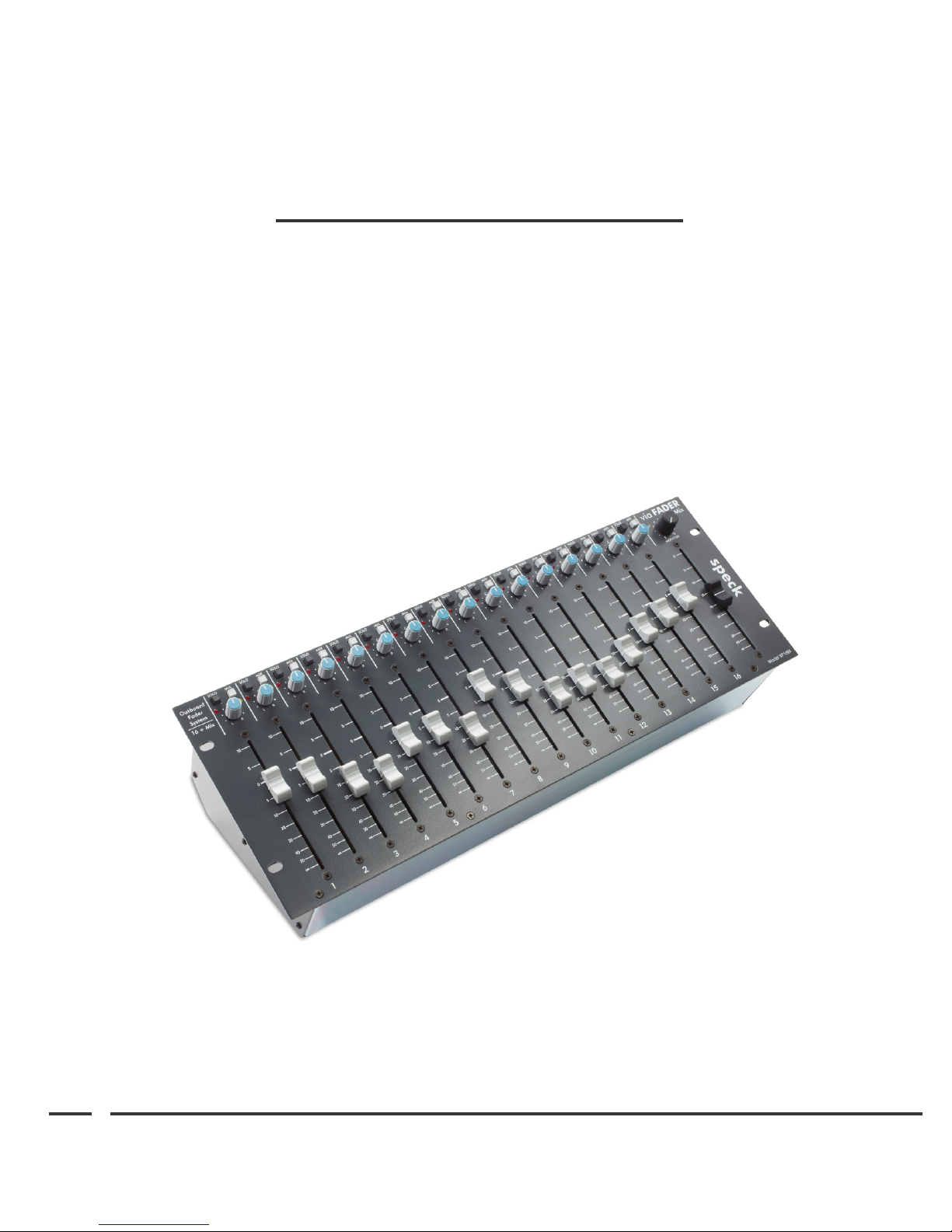
via Fader
Outboard Fader System
Models VF10M and VF16M
Reference Manual
speck electronics
Page 2

Warranty
ii
Speck Electronics products are warranted to the original owner to be free of
defects in material or workmanship.
This warranty does not apply to any product subject to accident, misuse,
neglect, or failure to comply with normal maintenance procedures, or if the
serial number has been defaced, altered, or removed; nor will Speck
Electronics accept responsibility for damages resulting from improper
installation, alteration or unauthorized parts or repairs. If the product is
modified by the customer without permission, the customer agrees to pay for
parts and labor necessary to remove the modification before repair. The cause
of the defect is in the sole judgment of Speck Electronics.
Should a defect develop within one year of purchase from Speck Electronics
or an authorized dealer, Speck Electronics will supply the part or parts
necessary at no charge. Labor is covered in this warranty for a period of one
year. Outside service, repairs, or pickups are not covered under this warranty.
Any item returned for warranty repair should be sent, if possible, in the
original packing container, prepaid to Speck Electronics, 341 E. Alvarado
Street, Fallbrook, California, 92028. If, in our opinion, the packing container
is improper for return shipping, we reserve the right to supply a new container
at a minimal charge.
In the interest of improving Speck products, designs and specifications are
subject to change without notice. It should be mentioned that if a change is
necessary for any reason, we make every effort to document
that change and send an "update notice" to all customers at no charge.
Notice
Speck Electronics makes no warranty of any kind with regard to this material,
including, but not limited to, the implied warranties of merchantability and
fitness for a particular purpose. Speck Electronics shall not be liable for
errors contained herein or for incidental consequential damages in connection
with the furnishing, performance, or use of this material.
This document contains proprietary information which is protected by
copyright. All rights are reserved. No part of this document may be
photocopied, reproduced, or translated into another language without the prior
written consent of Speck Electronics.
The information contained in this document is subject to change without
notice.
All trademarks are the property of their respective owners.
Speck Electronics
341 East Alvarado Street
Fallbrook, California 92028
USA
1+760-723-4281
www.speck.com
Page 3

Contents
Chapter 1 Introduction
General Description.....................................................................
via Fader Features .......................................................................
Standard Accessories ..................................................................
Optional Accessories ..................................................................
iii
2
3
3
3
Chapter 2 Installation
Chapter 3 Operation
General .......................................................................................
Unpacking and Inspection ..........................................................
Cleaning ......................................................................................
Mechanical Installation ..............................................................
Power Supply Installation ...........................................................
Physical Placement of Adjacent Equipment ...............................
Hooking up the via Fader ...........................................................
Linking Two via Faders ..............................................................
Overview ....................................................................................
Default Control Settings .............................................................
Signal Flow Diagram ..................................................................
Front Panel Controls ................................................................
Channel Fader........................................................................
Pan Control ...........................................................................
Mix Assign Switch................................................................
Solo Switch ...........................................................................
Stereo Master Fader ..............................................................
Monitor Level Control .........................................................
Power/Solo LED ...................................................................
Rear Panel .................................................................................
Fader Line Inputs ..................................................................
Fader Line Outputs ...............................................................
Mix Output Jacks ..................................................................
Mix Insert Jacks ...................................................................
Monitor Output Jacks ...........................................................
DC Power Inlet ....................................................................
Gain Select ...........................................................................
Mix/Solo Link Connectors ...................................................
AC Power Inlet ....................................................................
Fuse .......................................................................................
Power Switch ........................................................................
Mains Voltage Selector Switch .............................................
Specifications ..................................................................
5
5
5
6
6
6
7
8
9
9
10
11
11
11
11
11
12
12
12
13
13
13
14
14
14
14
15
15
16
16
16
17
18
Page 4
Chapter 1 Introduction Section 111
Introduction
Thank you for purchasing our via Fader Outboard Fader System. The via Fader (V.F.) has operational
features that are easy to understand and you should be up and running in no time. If you are unfamiliar
with audio equipment or audio signal flow, it is recommended that you read this manual. If you have any
questions regarding the V.F. or any Speck product, do not hesitate to contact Speck Electronics.
Speck Electronics
341 E. Alvarado Street
Fallbrook, CA 92028
Phone: +760-723-4281
Email: [email protected]
www.speck.com
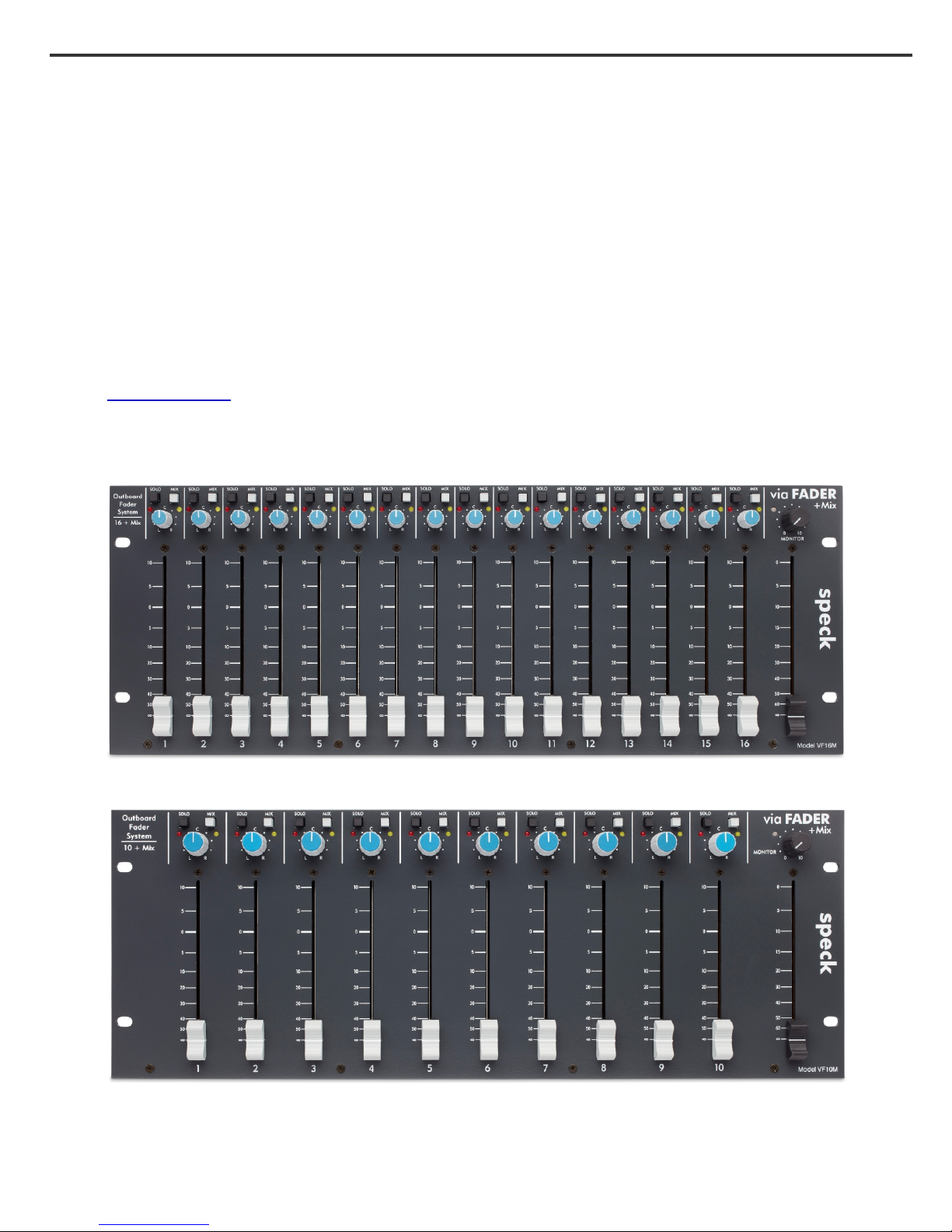
Model VF16M
Model VF10M
Page 5
Chapter 1 Introduction Section 2
General Description
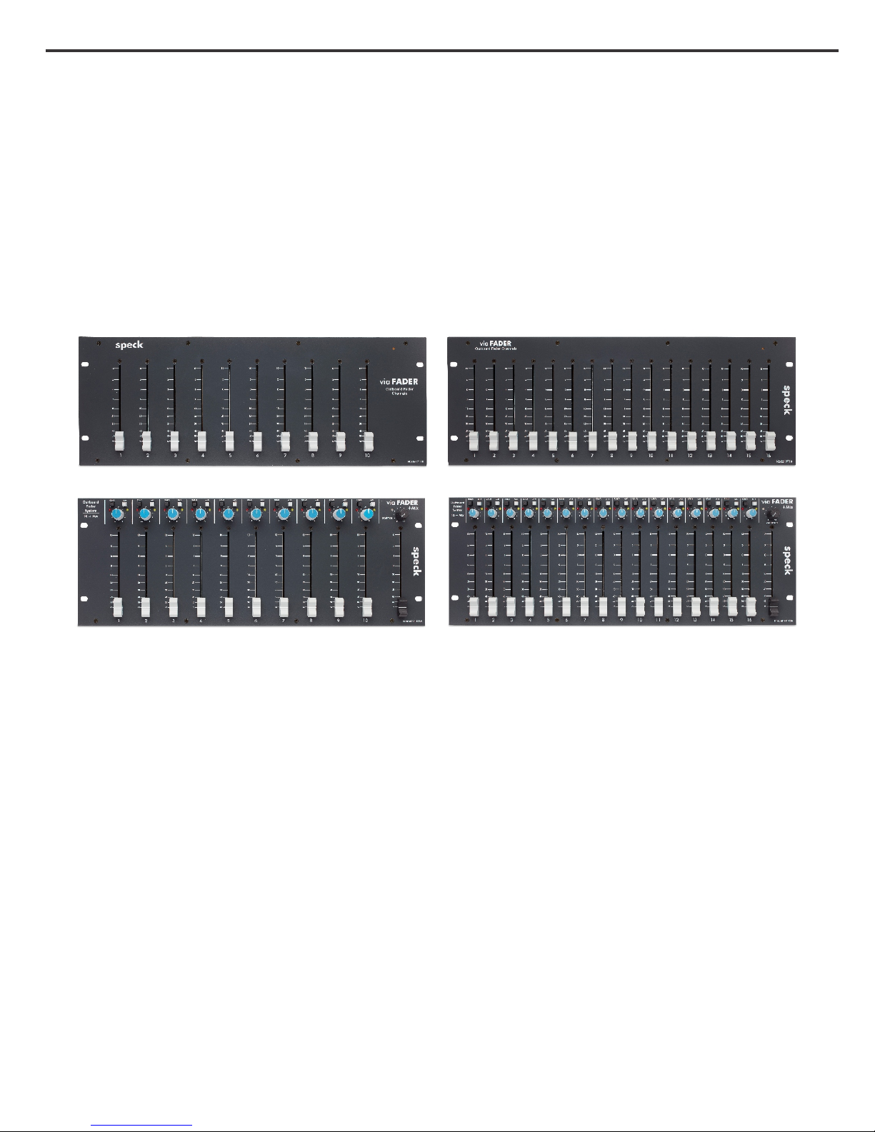
The via Fader is available in 4 models:
VF10 - 10 Outboard Fader Channels
VF16 - 16 Outboard Fader Channels
VF10M - 10 Channel Outboard Fader System with mix assign and master outputs
VF16M - 16 Channel Outboard Fader System with mix assign and master outputs.
Model VF10 Model VF16
Model VF10M Model VF16M
This manual has been prepared for the VF10M and VF16M. Unless otherwise noted, all references
in this manual will be for the via Fader Model VF16M, the 16 fader version with the mix section.
There is no operational difference between the two models except for the number of fader channels.
The via Fader (V.F.) is an outboard fader system available with 10 or 16 slide fader channels. No
VCA’s, no CMOS switching, and no A/D - D/A converters... just 100% analog signal path.
Each fader channel has the necessary input and output electronics to allow the V.F. to interface to any
balanced, unbalanced, transformer, or transformer-less line level signal. But most importantly... no
additional mixer or audio interface is required. The V.F. has high headroom that will handle balanced
signals up to +28dBu. All audio inputs and outputs are fully balanced and available on DB-25 and
TRS connectors.
With its clean, uncluttered layout, the V.F. can be placed in a convenient desktop location or installed
in your 19" rack.
The V.F. can be used as part of a 500 series Micpre g Compressor g Equalizer channel strip, for
external DAW summing, or as a line mixer for synths and samplers. In some cases, the V.F. can
eliminate the need for a mixing console in your studio. The master section has balanced inserts on the
mix outputs so you can patch your own external preamps to add character and color to your mix.
Page 6

Chapter 1 Introduction Section 3
via Fader VF10M and VF16M Features
Each fader channel has:
· Active-balanced input and output on a DB-25 connector.
· 100mm slide fader
· 10dB gain boost select for each channel.
· Mix assign switch that routes the fader channel to the main stereo mix
· Pan/balance control.
· In-place solo switch.
Master Section includes:
· 100mm Stereo Master slide fader.
· Monitor level provides adjustment to dedicated monitor outputs.
· Balanced 1/4” TRS stereo mix outputs.
· Balanced 1/4” TRS stereo monitor outputs.
· Balanced 1/4” TRS insert sends and returns for the mix section.
· Mix-solo link connectors.
Standard Accessories
· PS-6-V Power Supply
· Power cord (NA version only)
· Operations Manual
Optional Accessories
· VF-LINK2 Cable - The VF-LINK2 cable will connect the mix and solo busses
of two via Faders.
Page 7

Chapter 1 Introduction Section 4
~ This page left intentionally blank ~
Page 8

Chapter 2 Installation Section 5
Installation
General
The following information should give you the basics on how to install the via Fader (V.F.) mixer and
power supply. The proper installation of the V.F. requires a clear understanding of audio wiring, AC
distribution, grounding, and shielding techniques.
If the V.F. is being installed into a larger studio or as an expander to a host console, it may be
necessary to retain the services of someone experienced in these matters.
Unpacking & Inspection
The V.F. is delivered in a special protective container and was carefully inspected both mechanically
and electrically before shipment. All items should be physically free of mars and scratches and in
perfect electrical order upon receipt. To confirm this, the mixer and power supply should be inspected
for physical damage that may have occurred in transit. Any damage should be reported to your dealer
or delivery company as soon as possible.
If the product is to be shipped to Speck Electronics for service or repair contact Speck Electronics for
a Return Merchandise Authorization (RMA). Include the model number and serial number of the
product. Place the product in the original container if available. If the original container is not used,
wrap the product in heavy plastic before placing in an inner container. Use plenty of packing material
around all sides of the product and protect panel faces with cardboard strips. Mark shipping container
with "Delicate Instrument" or "Fragile", and insure the shipment for the proper amount.
Cleaning
To clean the front panel, wipe the surface gently using a soft lint-free cloth to avoid scratching the
panel or markings. Paper towels are not recommended. Commercially available window cleaner
solutions may be used; however, the solution should be applied to the cloth and not the panel to avoid
the seepage of liquid to the inside of the enclosure.
Do not use brushes or feather dusters to remove dust. This may cause dust to fall into the openings
around the slide fader and pushbutton switches.
Page 9

Chapter 2 Installation Section 6
Mechanical Installation
The via Fader was designed to be placed on a desktop or installed in a 19" rack. The location of the
via Fader should be such that the operator has a clear, unobstructed view of the front panel from
his/her normal operating position. The unit should also be within easy reach of the operators’ normal
position in order to facilitate the use of the front panel controls.
Power Supply Installation
One of the primary reasons that the power supply of the V.F. is external is to insure that the power
transformer enclosed within the power supply chassis maintains a safe distance from the active
electronics of the V.F. For that matter, any device that has a strong magnetic power field should be
kept at a reasonable distance from the V.F. and its audio cables.
Because the power supply does not use a cooling fan, it is silent and can be located in the same room
as the mixer. However, it is important that the ventilation holes are not obstructed and that the unit is
operated in free air to prevent overheating. Allow a minimum of 4” (100mm) of clearance from all
ventilation holes.
Use only the PS-6-V external power supply that is supplied with your V.F. mixer. Using any
other power supply or power source will most definitely damage the V.F.
The V.F.'s power supply can operate with two AC mains voltage settings of 115 VAC or 230 VAC
50/60 Hz. Before switching “on” the power, you should verify that the voltage setting on your power
supply is configured to match the AC mains requirements of your country. If the AC mains voltage
needs to be changed see “Voltage Selector Switch” (Page 17).
Before connecting the DC power supply cable to the V.F., make certain the power switch is set to the
“off” position. To connect the power supply to the mixer, fit the 10 pin rectangular connector from the
power supply to the chassis mount receptacle on the bottom of the V.F. The respective connectors are
keyed so the plug and the receptacle can fit in only one direction.
Always turn the power supply “off” and disconnect the
!
DC power cable before servicing the via Fader.
Physical Placement of Adjacent Equipment
Any device that emits a high EMI (Electro Magnetic Interference) or RFI (Radio Frequency
Interference) energy field should be treated with suspicion. EMI is considered any unwanted signal
which adversely affects the operation of the via Fader or the mixing system.
Electronic equipment such as power amplifiers, power supplies (especially wall mount type), video
monitors, computers, certain synths and samplers must be located away from the V.F. and its
associated cables. It may be necessary to alter the positions of certain equipment that you feel would
cause buzzes or hums in the mixer system.
Page 10

Chapter 2 Installation Section 7
BALANCED INPUTS 1-8 BALANCED INPUTS 9-16 BALANCED OUTPUTS 1-8 BAL ANCED OUTPUTS 9-16
Hooking up the via Fader
The via Fader will require a minimum of two (2) DB-25 harnesses to operate; one (1) for the inputs
and one (1) for the outputs. A complete system will require a maximum of four (4) DB-25 harnesses
and various 1/4” TRS cables.
Care should be taken to support the DB-25 audio harnesses as not put stress on the chassis
mounted DB-25 connectors.
Due to the high performance of the V.F. it is recommended that you use only the highest quality audio
cable. A high quality cable by definition is a cable that provides good mechanical strength, high
microphonic noise immunity, high frequency response, low crosstalk, and 100% shielding ability. All
audio cable used with the V.F. should be a 3 conductor foil shield type (2 inner conductors and a shield
drain conductor). It is not recommended that the 2 conductor "off the shelf cables" be used.
All wire and cable interfaced to the V.F. should be terminated with high quality connectors. A ¼" plug
or XL connector should make a positive connection to its respective mating jack and provide adequate
strain relief to its cable. All connectors should also have a metal shell to provide 100% shield for
exposed conductors.
We do believe that “you get what you pay for” and advise not to purchase lower quality cables. We
recommend that you purchase from a reputable cable manufacturer that uses brand name materials.
Brand name cables include (in no particular order) Mogami, Canare, Belden, Gepco, Redco, and
ProCo. Connector brands include Switchcraft and Neutrik.
When the time comes to actually interconnect your equipment, proceed slowly. Interfacing the many
pieces of electronic equipment to your via Fader and audio system should be a logical and methodical
process. Start by connecting only the monitor power amp (or active monitors) to the V.F. and then
connect one line signal at a time; carefully listening and monitoring your progress. If a problem arises,
such as a buzz, hum, intermittent signal, or nonexistent signal, stop at that point and solve the problem
before proceeding.
Page 11
Chapter 2 Installation Section 8
Linking two via Faders
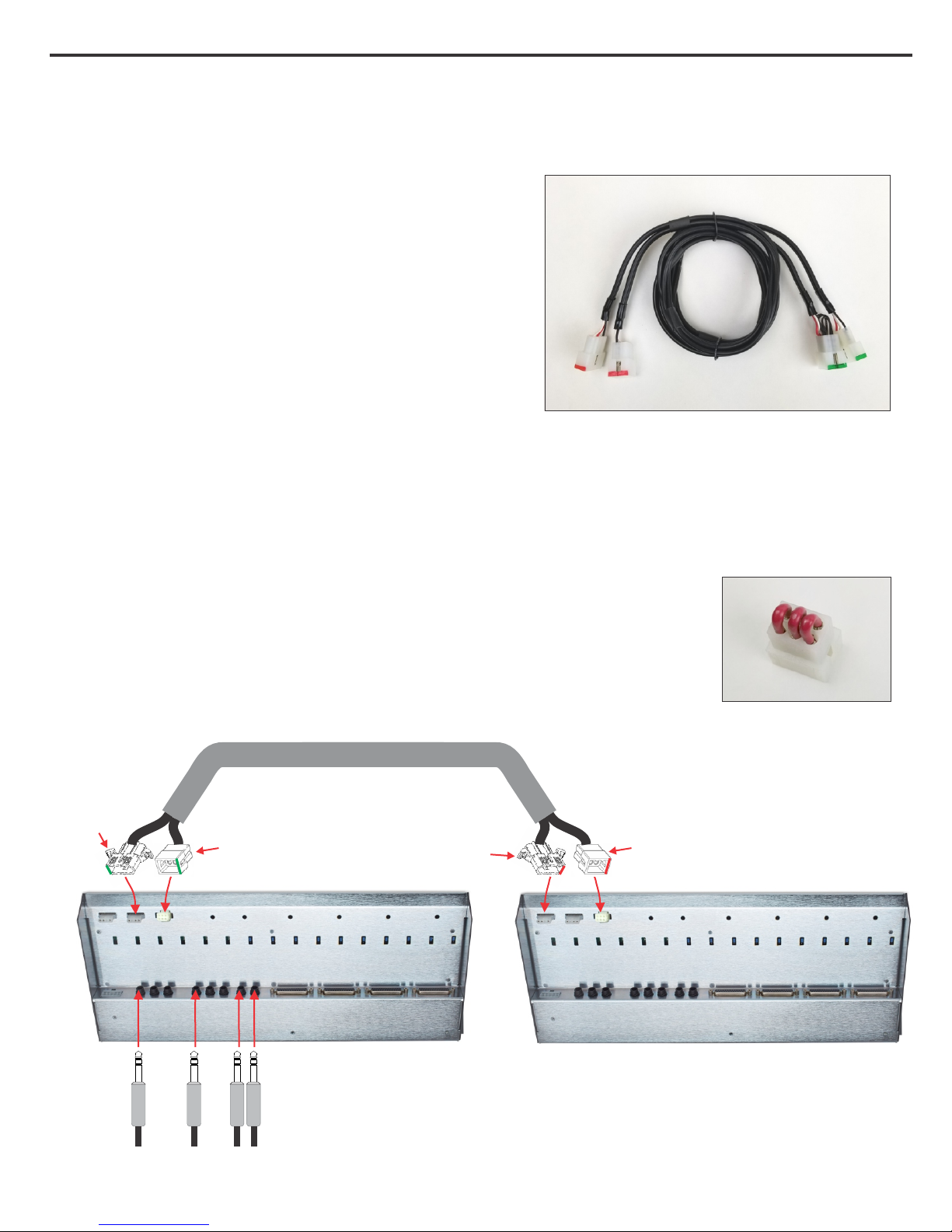
The via Fader models VF16M and VF10M have 3 (V.F.)
white nylon connectors (See Item [15]) on the bottom
panel that can be used to link the mix and solo busses
with a second V.F. When the two V.F.'s are linked
together, one V.F. will become the MAIN and the other
will become the EXPANDER (as shown below).
By linking two V.F.'s the stereo master fader, the
monitor master, and all 1/4” TRS jacks on the V.F. that
you chose to be the MAIN then become the master for
both the MAIN and EXPANDER. All fader outputs on
the DB-25 connectors remain independent.
VF-LINK2 Cable
Figure 1.
Connect end with
the GREEN mark to
4 pin MIX LINK IN
receptacle.
An optional VF-LINK2 cable (Figure 1) is required to perform the link. The VF-LINK2 cable is wired
with 2 nylon plugs on each end that connect to the chassis mounted receptacles and will automatically
link the mix and solo busses. Connect the green marked plugs to the V.F. that you want to be the
MAIN mixer and connect the red marked plugs to the V.F. that you want as the EXPANDER.
Before attaching the V.F. link cable you must remove the factory installed plug
(Figure 2) with the red wires on both via Faders.
Contact your dealer or Speck Electronics directly to purchase the optional
VF-LINK2 mix link cable.
VF-LINK2 Cable
Before proceeding, remove the
factory installed connector with
3 red wires.
Then connect the end of this
cable with the GREEN mark to
the 6 pin Solo receptacle on the
MAIN unit.
Connect end with
the RED mark to
4 pin MIX LINK OUT
receptacle.
Before proceeding, remove the
factory installed connector with 3
red wires.
Then connect the end of this cable
with the RED mark to the 6 pin
Solo receptacle on the EXPANDER
unit.
Remove this plug before
installing VF-LINK2 cable
Figure 2.
Mix Out
Left
Right
Monitor Out
Left
Right
Main
Expander
Page 12
Chapter 3 Operation Section 9
Operation
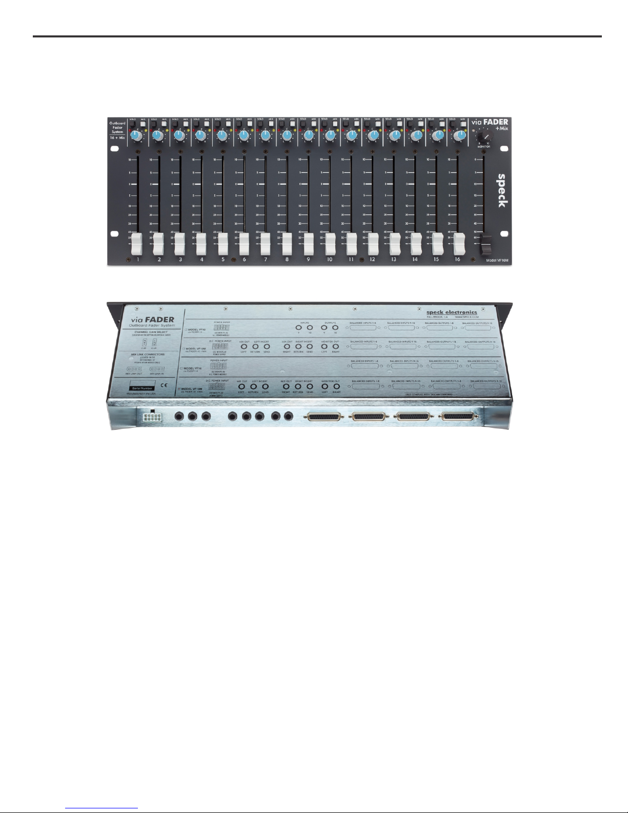
Model VF16M Top
Model VF16M Rear
Overview
In this section we hope to give you basic information on the operation of the via Fader (V.F.) and
adequately describe its controls, switches, and connectors.
The information in this section of the manual is intended to help with the technical process when using
your V.F. Words alone could not adequately describe how to adjust the controls for every situation you
might encounter with the V.F. You should experiment with settings and routing techniques to achieve
the best results for any particular situation. Your ears should be your best gauge of how to adjust the
settings on the V.F. to make the sound fit your requirements.
Default Control Settings
Before any attempt is made to operate the V.F., it would be a good idea to set all controls to their
neutral positions. This gives you a reference point to work from when adjusting controls and switches.
All slide faders should be set to their full off (∞) setting. All pan controls should be set centered. All
pushbutton switches should be set to the out position.
When any future reference is made to the controls or switches on the via Fader, it will be assumed that
they have been set to their neutral positions.
Page 13
Chapter 3 Operation Section 10
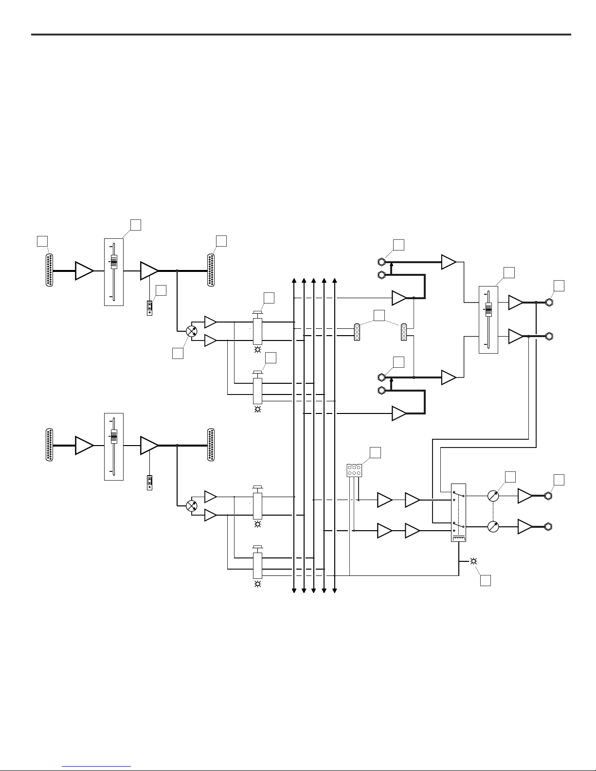
Signal Flow Diagram
Use this channel signal flow diagram shown below as a reference when reading the descriptions of the
controls, switches, and connectors [1] through [15] in this chapter.
8
BALANCED
INPUTS 1-8
Typical of channels 1-8
0
1
0
8
FADER
1
UNITY
10dB
FADER GAIN
SELECT
14
9
BALANCED
OUTPUTS 1-8
3
MIX
PAN
2
SOLO
4
RETURN
SEND
LINK IN
RETURN
SEND
MIX
MIX LEFT
INSERT
15
LINK OUT
MIX RIGHT
INSERT
11
STEREO
5
MASTER
FADER
S
MIX
0
0
1
8
10
LEFT
MIX
OUTPUT
RIGHT
11
FADER
0
1
BALANCED
INPUTS 9-16
0
8
Typical of channels 9-16
UNITY
10dB
FADER GAIN
SELECT
S
BALANCED
OUTPUTS 9-16
MIX
SOLO LINK
15
S
PAN
S
SOLO
MIX BUS-R
MIX BUS-L
SOLO BUS-L
SOLO BUS-R
SOLO LOGIC
Figure 3. via Fader signal flow and reference designations.
SOLO
RELAY
MONITOR
LEVEL
SOLO
INDICATOR
7
6
12
LEFT
MONITOR
OUTPUT
RIGHT
Page 14
Chapter 3 Operation Section 11
FRONT PANEL CONTROLS
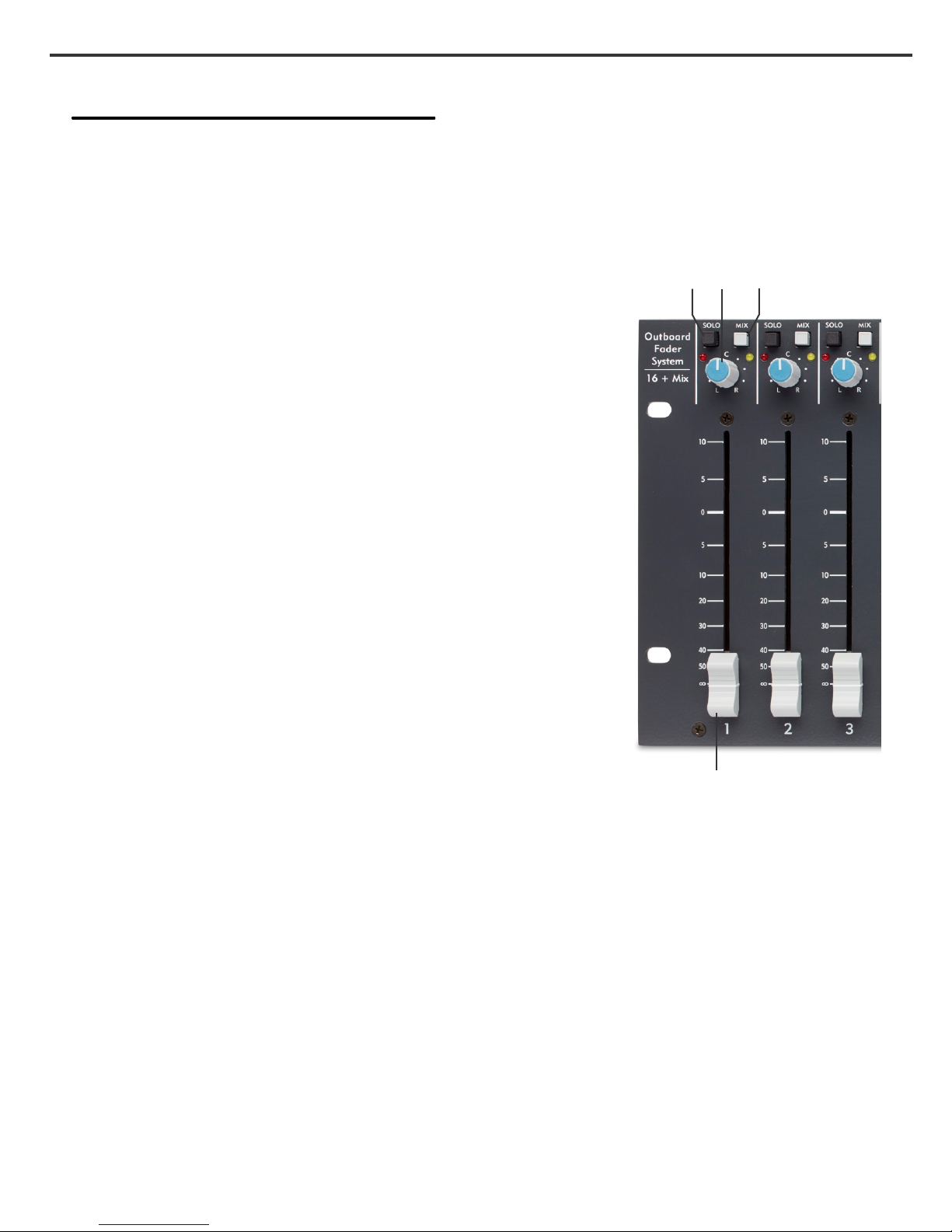
1. Channel Fader
This 100mm slide fader adjusts the level of its respective
channel and has a range of ∞dB to 10dB. The operation of the
slide fader adjusts the level to both the fader line output and
stereo mix. The “0” mark is the "unity gain" setting for the fader
channel.
Fader In to Fader Out Gain
With a balanced +4dBu signal present at a DB-25 line input
and its respective fader set to the “0” mark, the corresponding
balanced DB-25 line output will be +4dBu.
Fader In to Mix Out Gain
With a balanced +4dBu signal at one DB-25 line input, fader
set to the “0” mark, Mix Switch enabled, Pan Control set to
the center position, and Stereo Master Fader set to maximum
“0” mark, the balanced left and right mix outputs will be
+4dBu.
With the Gain Select [14] set for 10dB and the slide fader set at
the “10” mark this will give the channel a total of 20dB of gain.
It is recommended that the fader channels be set to the "0" mark
when the V.F. is being used exclusively as a summing mixer.
4 32
2. Pan Control
This center detent pan control places the channel anywhere in
the stereo left/right mix when the Mix Assign Switch [3] is
enabled.
3. Mix Assign Switch
The Mix Assign switch, in conjunction with the Pan Control [2], allows an input channel to be mixed
to the left and right main mix output. The operation of the Mix Assign Switch does not affect the
signal at the DB-25 line outputs. A yellow L.E.D. indicates that the channel has been assigned to the
Mix outputs.
4. Solo Switch
Depressing this switch allows you to isolate any fader channel to the monitor outputs while
maintaining stereo perspective - also known as In-Place solo.
Any combination of fader channels may be soloed without interrupting the flow of the signal to the
main mix feed. A red LED on this switch as well as the Power/Solo [7] indicator will illuminate if a
channel is soloed.
1
Page 15
Chapter 3 Operation Section 12
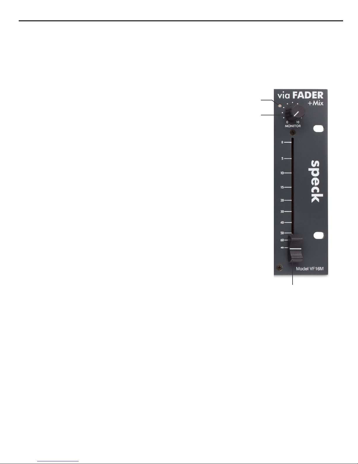
5. Stereo Master Fader
This 100mm dual slider is the master volume to the active-balanced
mix outputs. The master fader has a range of ∞dB to 0dB.
Under normal operating conditions the fader should always be set at
maximum. If it has to be pulled down a significant distance it indicates
that the levels at the fader channels are too high and should be reduced.
6. Monitor Level Control
This adjusts the overall level to the stereo Monitor Output Jacks [12]
on the rear panel. The Monitor Master typically controls the volume to
a stereo power amplifier or powered speakers.
7. Power/Solo LED
This LED will illuminate green when the power is applied to the via
Fader. When any solo is depressed, this LED will change from green
to red.
7
6
5
Page 16
Chapter 3 Operation Section 13
REAR PANEL
8
BALANCED INPUTS 1-8 BALANCED INPUTS 9-16 BALANCED OUTPUTS 1-8 BAL ANCED OUTPUTS 9-16
9
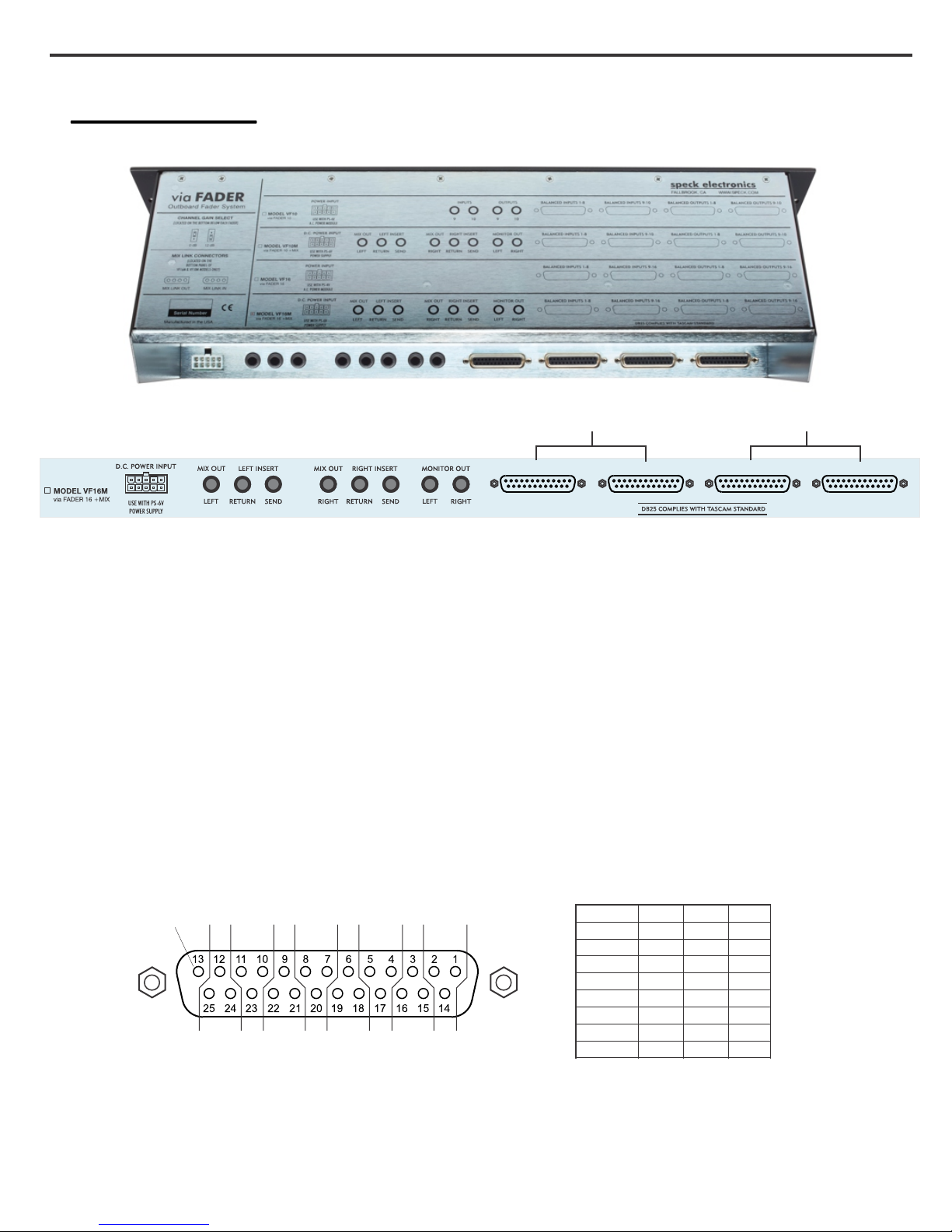
8. Fader Line inputs
There are two DB-25 connectors for the fader line inputs. These balanced inputs will accept a +4dBu
reference signal.
Note: Inputs 11-16 not used on the Model VF10M
9. Fader Line outputs
There are two DB-25 connectors for the fader line outputs. With a balanced +4dBu signal present at
the DB-25 line input and the slide fader set to the “0” mark, the balanced DB-25 line output will be
+4dBu.
Note: Outputs 11-16 not used on the Model VF10M
The DB-25 connectors conform to the Tascam standard pin layout
Not Used
Figure 4
NOTE - All active-balanced output circuits of the via Fader were designed for balanced
lines and should only be connected to balanced inputs. If that is not possible and it is
necessary to connect to an unbalanced input, care must be taken not to connect the low
(-) terminal to ground. If the low (-) terminal of these outputs is connected to ground, the
result may be a high level of audio distortion.
Channel
87654321
High
1
2
3
4
5
6
7
8
24
10
21
7
18
4
15
1
Low
12
23
9
20
6
17
3
14
Gnd
25
11
22
8
19
5
16
2
Page 17
Chapter 3 Operation Section 14
11
BALANCED INPUTS 1-8 BALANCED INPUTS 9-16 BALANCED OUTPUTS 1-8 BAL ANCED OUTPUTS 9-16
13
10 12
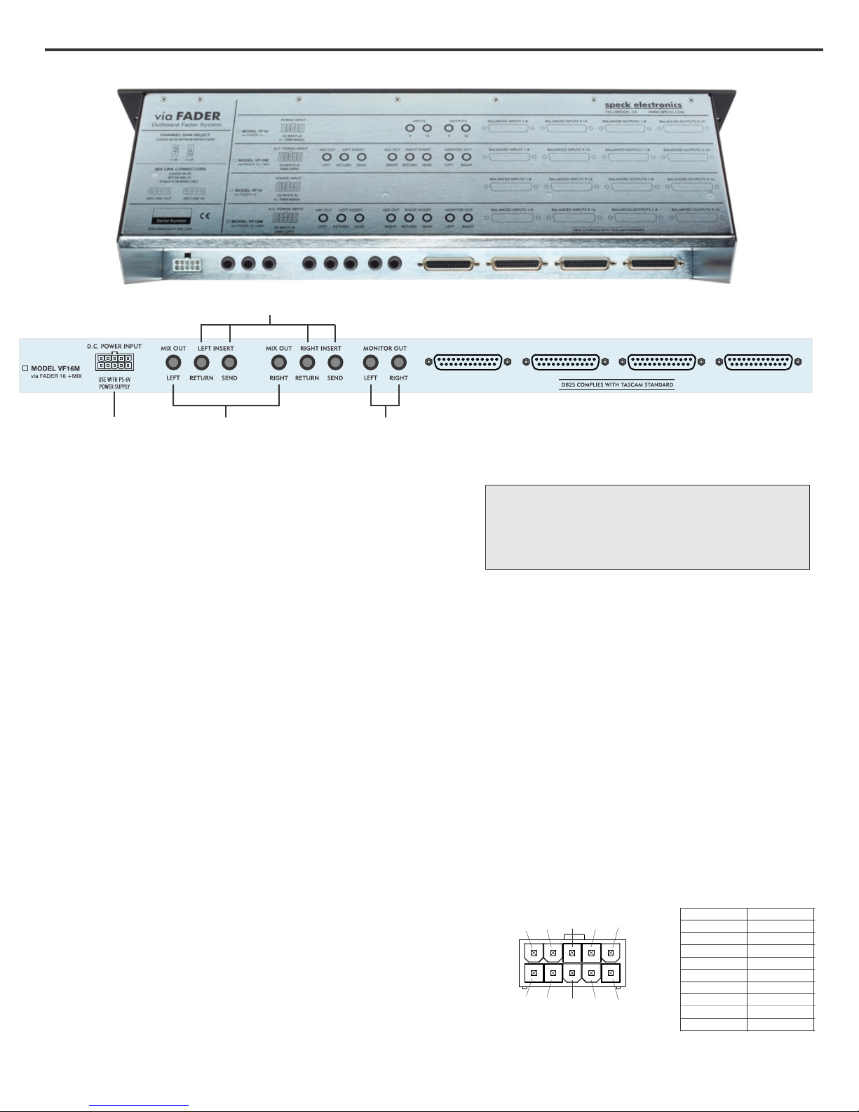
10. Mix Output Jacks
These balanced 1/4" TRS phone type connectors are
the left and right outputs for the stereo mix bus. The
signal present at these jacks is adjusted by the Stereo
Master Fader [5] on the top panel.
The pin configuration for all ¼" TRS jacks is:
Tip=High (+), Ring=Low (-), Sleeve=Ground
11. Mix Insert Jacks
The mix output section has balanced sends and returns available via separate ¼” TRS jacks. The
Insert Jacks provide line level inter-stage access to the mix bus before (pre) the stereo Master Fader.
This means that any device interfaced to these jacks will not be affected by any adjustments of the
Stereo Master Fader.
The insert jacks may be utilized to connect processors such as limiter/compressor or equalizers.
Another function of the insert connectors is to let you connect your own external preamps to the via
Fader should you want to experiment with a more "colored" sound.
12. Monitor Output Jacks
These balanced 1/4” TRS jacks are available for hooking up a power amp or powered speakers. The
signal present at these jacks is adjusted by the Monitor Master [6] control on the top panel.
13. DC Power Inlet
The DC power cable from the power supply connects to
this 10 pin rectangular connector. This connector and its
respective plug are keyed so they will only fit in one
direction. For power supply installation instructions,
refer to the Interface Section in this manual.
The connector illustration and chart as shown in Figure 5
represents the DC voltages to power the via Fader.
10 9
5 4
8
3
Figure 5
7 6
2 1
PIN 1
PIN 2
PIN 3
PIN 4
PIN 5
PIN 6
PIN 7
PIN 8
PIN 9
PIN 10
+16.5 VDC
0 VDC
0 VDC
-16.5 VDC
+16.5 VDC
0 VDC
-16.5 VDC
Page 18
Chapter 3 Operation Section 15
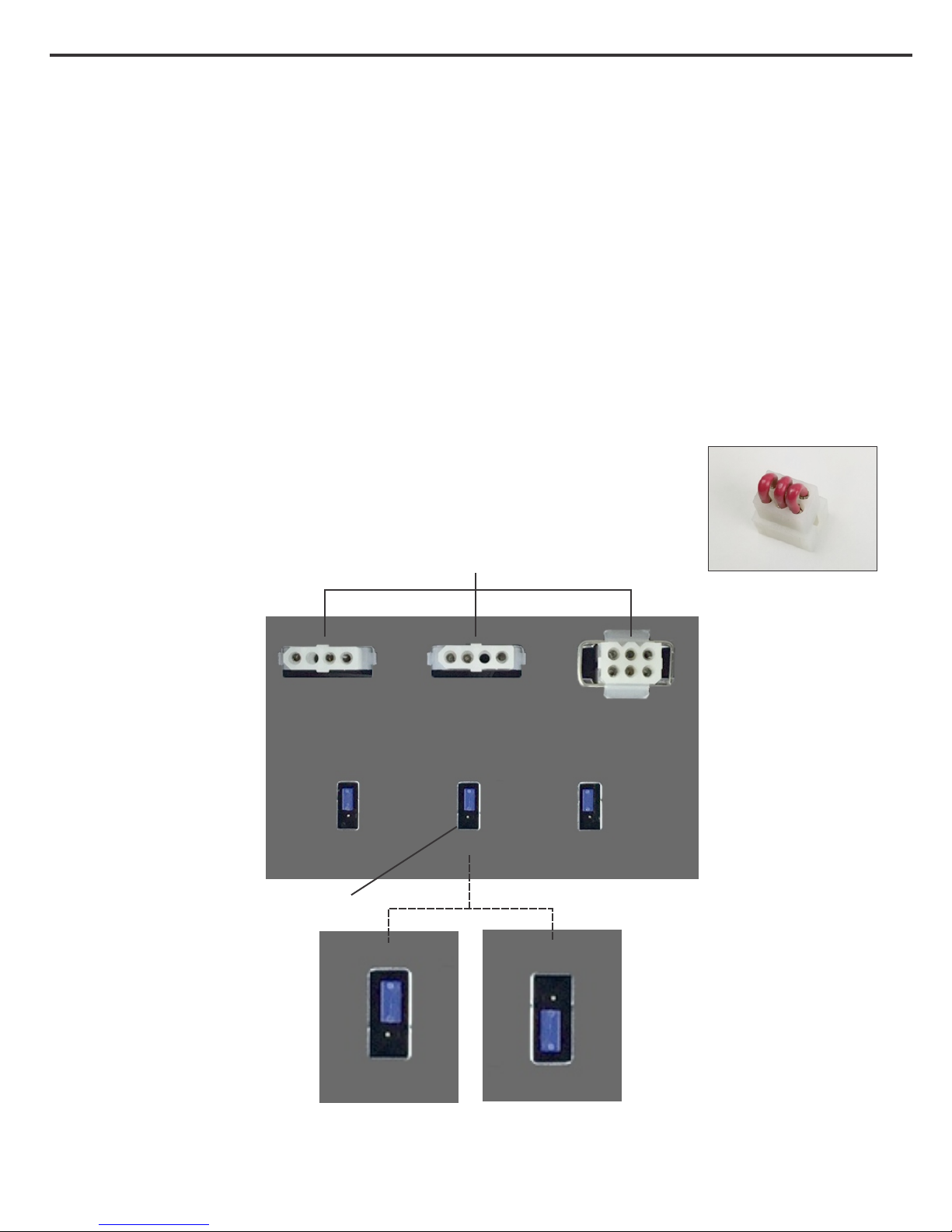
14. Gain Select
Each channel has a gain select jumper directly below the fader on the bottom panel (See Figure 7).
The factory default setting is for 0dB of gain. 10dB of gain can be added to the channel by moving
the position of the jumper. With the gain select set for 10dB and the slide fader set at the “10” mark
this will give the channel a total of 20dB of gain.
15. Mix/Solo Link Connectors
The via Fader models with the mix section (VF16M or VF10M) have 3 white nylon connectors on
the bottom panel that can be used to link the mix and solo busses with a second V.F. When two V.F.'s
are linked together, one V.F. will become the MAIN and the other will become the EXPANDER.
(See page 8)
The V.F. is shipped with a jumper plug (Figure 6) fitted to the Solo Link
connector. The plug can be identified by its 3 red wires. The plug must
remain in place for the V.F solo to operate. Only remove the plug when a
VF-LINK2 expander cable is used.
Mix Link Out
14
15
Figure 6.
Mix Link In
Solo Link
Gain Select
0dB Setting 10dB Setting
(Factory Default)
Figure 7.
Page 19
Chapter 3 Operation Section 16
18
16
17
19
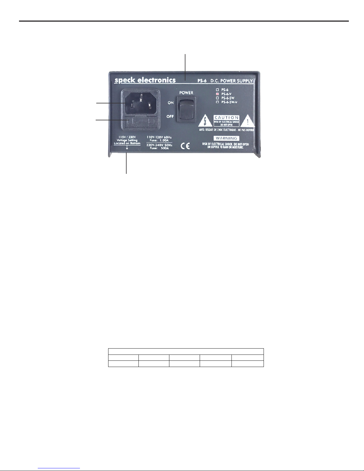
16. AC Power Inlet
This AC (mains) power inlet accepts a standard IEC power cord. Before connecting the power cord,
make certain the power cord matches the operating voltage indicated on the voltage selector switch
[19].
The ground pin of the power cord is internally connected to the chassis. For safety reasons, do not
lift the ground on the power plug by using a ground lift adapter.
17. Fuse
The AC power inlet has an integral fuse holder that uses a 5mm x 20mm slow blow (T) type fuse. To
avoid the risk of fire, always replace the fuse with the correct value; .5 amp for the 115V model, or
.25 amp for the 230V model.
In the unlikely event that a fuse blows, it is EXTREMELY important that a fuse of the same type and
current rating be replaced. The chart below (Figure 8) lists the fuse current ratings to be used for
your countries mains voltage.
Fuse Chart for PS-6-V
100 VAC 120 VAC 220 VAC 230 VAC 240 VAC
.5 Amp .25 Amp .5 Amp .25 Amp .25 Amp
Figure 8.
Power Supply
18. Power Switch
This ON/OFF power switch applies AC (mains) power to the PS-6-V power supply and the via Fader
mixer.
Page 20
Chapter 3 Operation Section 17
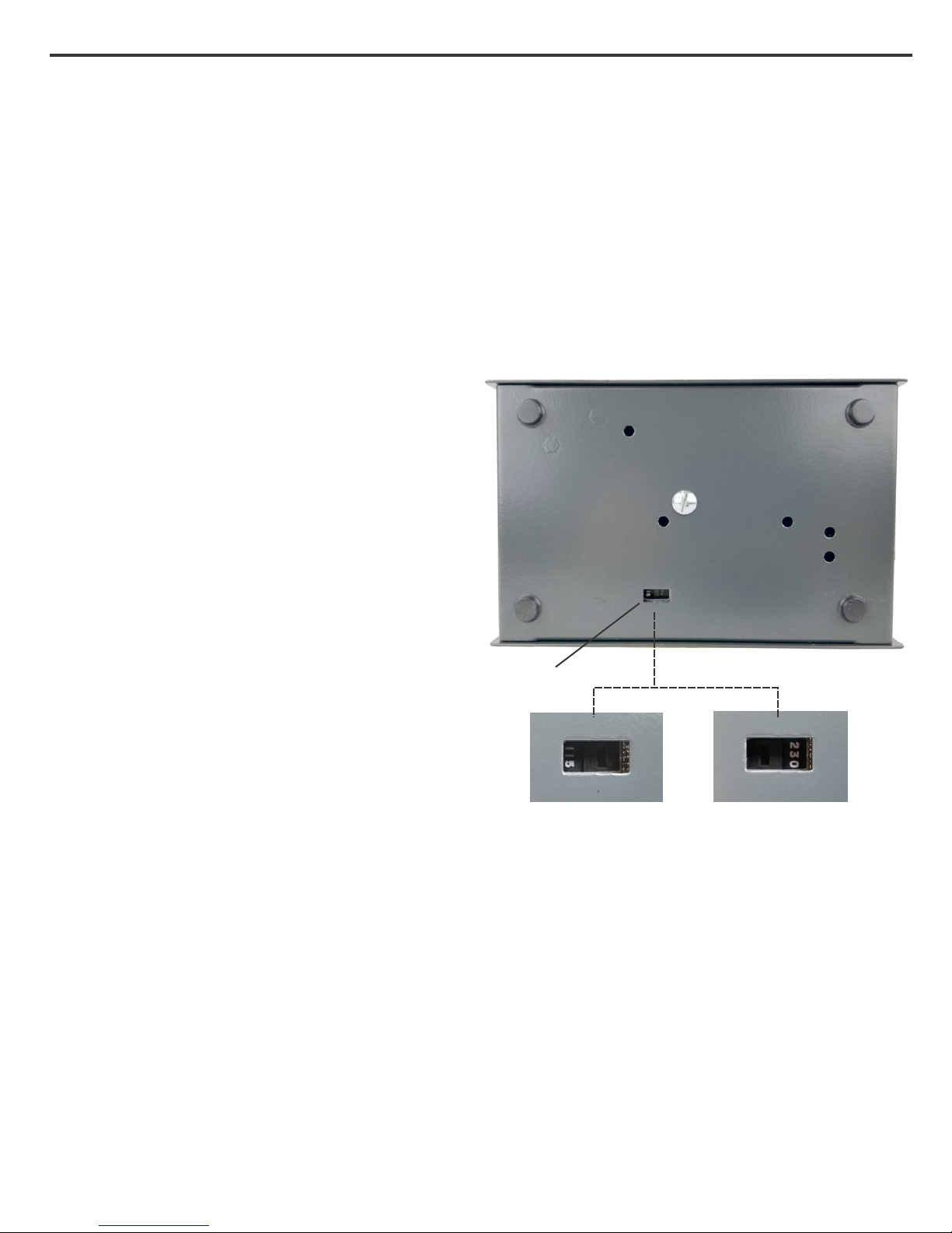
19. Voltage Selector Switch
The PS-6-V power supply for the via Fader will operate at mains voltages of 100-120 VAC or 220240 VAC. The voltage has been set at the factory.
If it becomes necessary to change the mains voltage, there is a voltage selector switch accessible
from the bottom of the power supply chassis as shown in Figure 9. The cover does not need to be
removed to gain access to the selector switch.
Always remove the power cord from the
power inlet [16] before changing the
115/230 voltage selector.
If your mains voltage is 100VAC or
120VAC, set the voltage selector switch to
the “115” position. If your mains voltage is
220VAC, 230VAC or 240VAC, set the
voltage selector switch to the “230”
position.
After setting the new mains voltage change
the fuse according to the chart shown in
Figure 8, on Page 16.
19
Figure 9.
Do not remove covers or panels
To avoid personal injury, do not remove the top cover from the power supply and
never operate the external power supply without the cover properly installed. If it
becomes necessary to service any part of the mixer, always unplug the AC power
and disconnect the DC interface cable before proceeding.
Page 21

Chapter 3 Operation Section 18
Specifications
Line input impedance
Balanced
Unbalanced
30K ohms
15K ohms
Maximum input level
Output Impedance
All Active-balanced outputs
Maximum output level (2k load)
All Active-balanced outputs
Frequency Response (10 dB gain)
Fader input to fader output
Fader input to mix output
THD+n
+12dBu any fader input, fader set at “0” mark, +12dBu fader out
+12dBu any fader input, fader set at “0” mark, +12dBu mix out
Crosstalk (1kHz)
Channel to channel
Input to Mix out, input fader off, channel mix deselected
Noise (22Hz-22kHz)
Residual Mix output noise
16 channels routed, faders off
DC Power Requirements (Mixer)
VF16M
VF10M
+28dBu
60 ohms
+28dBu (Balanced)
3Hz-54kHz (+0/-.5dB)
3Hz-54kHz (+0/-.5dB)
.0024%
.0024%
-102dBu
-89dBu
-102dBu
-87dBu
+/- 16 VDC +520ma/-360ma
+/- 16 VDC +390ma/-260ma
AC Power Requirements (External supply)
Dimensions (Mixer)
Dimensions (External supply)
Weight (Mixer)
Weight (External supply)
Total shipping weight
100-120 VAC 50/60Hz .5 amp
220-240 VAC 50/60Hz .25 Amp
WxDxH=19" x 7" x 6"
(483mm x 178mm x 158mm)
WxDxH=4.6" x 2.75" x 7.3"
(117mm x 70mm x 185mm)
14 Lbs (6.4kg)
3 Lbs (1.4kg)
19 Lbs (9kg)
 Loading...