

Page 1
WARNING
Installation must be done by an electrician qualified
in the installation and service of control systems
for heating equipment.
Improper installation, adjustment, alteration, service
or maintenance can result in death, injury or
property damage. Read the Installation, Operation
and Service Manual thoroughly before installing or
servicing this equipment.
Installation Manual
© 2017 Specified Air Solutions
Installer
Please take the time to read and understand
these instructions prior to any installation.
Installer must give a copy of this manual to the owner.
Owner
Keep this manual in a safe place in order to provide
your service technician with necessary information.
Specified Air Solutions
1250 William Street
Buffalo, New York 14206
Telephone: +1.716.852.4400
Fax: +1.716.852.0854
Toll Free: 800.828.7450
www.specifiedair.com
P/N 1010100 NA Orig
Page 2

Page 3

© 2017
Roberts-Gordon LLC
All rights reserved. No part of this work covered by the copyrights herein may be reproduced
or copied in any form or by any means - graphic, electronic, or mechanical, including
photocopying, recording, taping or information storage and retrieval systems - without the
written permission of Roberts-Gordon LLC.
TABLE OF CONTENTS
SECTION 1: Introduction........................................................ 1
1.1 Safety ...........................................................................1
1.2 California Proposition 65 ..............................................1
1.3 What is SPECIFIED AIR SOLUTIONS
™
VIRTUAL
WALL™ Controller? .....................................................1
1.4 General Requirements .................................................1
1.5 Example Site Layout..................................................... 1
1.6 Carton Contents ...........................................................3
SECTION 2: Specifications ....................................................5
2.1 VIRTUAL WALL
™
Controller.........................................5
2.2 Repeater......................................................................5
SECTION 3: Installation.......................................................... 7
3.1 Preparation ..................................................................7
3.2 Positioning the VIRTUAL WALL™ Controller............... 7
3.3 Cable Requirements ....................................................7
3.4 Check Installation Materials .........................................7
3.5 Electrical Installation Requirements of VIRTUAL
WALL™ Controller .......................................................8
SECTION 4: Wiring Diagram .................................................. 9
SECTION 5: Communications.............................................. 11
5.1 WebCTRL
®
................................................................ 11
5.2 Communications Between Multiple SAS Products..... 11
5.3 Setting Baud Rate...................................................... 12
5.4 Control Board Setup ..................................................12
5.5 Sequence of Operations............................................ 15
SECTION 6: WebCTRL®.......................................................17
6.1 Touchscreen Gestures...............................................17
6.2 Navigating.................................................................. 17
6.3 Graphics .................................................................... 18
6.4 Managing Connections.............................................. 19
6.5 Miscellaneous Actions ...............................................20
6.6 User Login & Operator Access .................................. 21
6.7 Scheduling.................................................................22
6.8 Trending.....................................................................25
6.9 Alarms .......................................................................29
6.10 Reports ....................................................................30
6.11 Refining the System .................................................33
SECTION 7: Replacement Parts ..........................................34
7.1 VIRTUAL WALL™ Controller Replacement Parts ...... 35
SECTION 8: The VIRTUAL WALL
™
Controller Limited
Warranty............................................................36
Page 4

Page 5
SECTION 1: INTRODUCTION
DANGER
Electrical Shock Hazard
Disconnect electric before service.
Controller must be properly grounded to an
electrical source.
Failure to follow these instructions can
result in death or electrical shock.
1. 1 S a f e t y
Yo ur Safety is Important to Us!
This symbol is used throughout
the manual to notify you of
possible fire, electrical or burn
hazards. Please pay special attention when reading and following
the warnings in these sections.
Installation, service and annual inspection of
controller must be done by an electrician qualified in
the installation and service of control systems for
heating equipment.
Read this manual carefully before installation,
operation, or service of this equipment.
The controller must be applied and operated under
the general concepts of reasonable use and installed
using best building practices.
This controller is not intended for use by persons
(including children) with reduced physical, sensory or
mental capabilities, or lack of experience and knowl-
edge,
unless they have been given supervision or
instruction concerning use of the controller by a person responsible for their safety.
SECTION 1: INTRODUCTION
™
1.3 What is SPECIFIED AIR SOLUTIONS
VIRTUAL WALL™ Controller?
The VIRTUAL WALL
™
Controller is an integrated
control system designed to automate the environ-
ment control and energy usage of all heating, cooling, and ventilation products supplied by SPECIFIED
™
AIR SOLUTIONS
via a single access point. Capable of communicating directly with Specified Air
HVAC equipment to allow for custom set points in
occupied or unoccupied areas and/or times. This
customization of the facility's environment maximizes
efficiency by dividing occupied areas into separate
zones while improving indoor air quality.
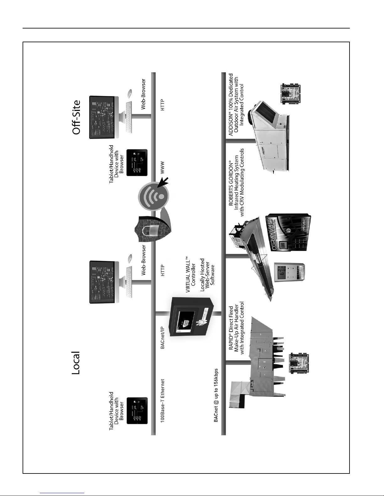
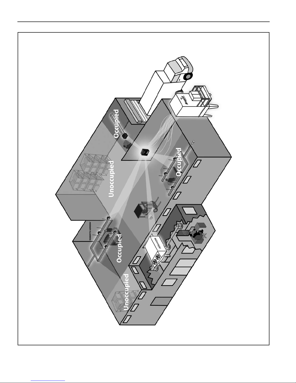
For the overall view of connected components for
VIRTUAL WALL
™
Controller, see Page 2, Figure 1.
System status and settings are viewed and altered
from a PC or smart device (not supplied).
1. 4 G e n e r a l Re quirements
Children should be supervised to ensure that they do
not play with the controller.
For optimum performance and safe operating conditions, inspect and maintain controller(s) before every
use and as necessary. If you require additional man-
uals, contact your SPECIFIED AIR SOLUTIONS
independent distributor or Specified Air Solutions at
(716) 852-4400, (800) 828-7450 or at www.specifie-
dair.com.
1.2 California Proposition 65
In accordance with California Proposition 65 require-
ments, a warning label must be placed in a highly
visible location on the outside of the equipment (i.e.,
near equipment’s serial plate).
™
The VIRTUAL WALL™ Controller series of controllers are supplied pre-configured for use with Specified Air HVAC equipment. Failure to comply with the
installation instructions and configuration may invali-
date the VIRTUAL WALL
™
Controller limited war-
ranty. See Page 36, Section 8.
The controller must be electrically grounded in accordance with the National Electrical Code
®
ANSI/NFPA
70 - latest revision.
1.5 Example Site Layout
Page 4, Figure 2 is an example layout for a building
where SPECIFIED AIR SOLUTIONS
™
VIRTUAL
WALL™ Controller will be used to control the HVAC
systems shown. The layout consists of zones of VIR-
™
TUAL WALL
Controller.
1
Page 6
VIRTUAL WALL™ CONTROLLER INSTALLATION MANUAL
FIGURE 1: Connected Components
2
Page 7
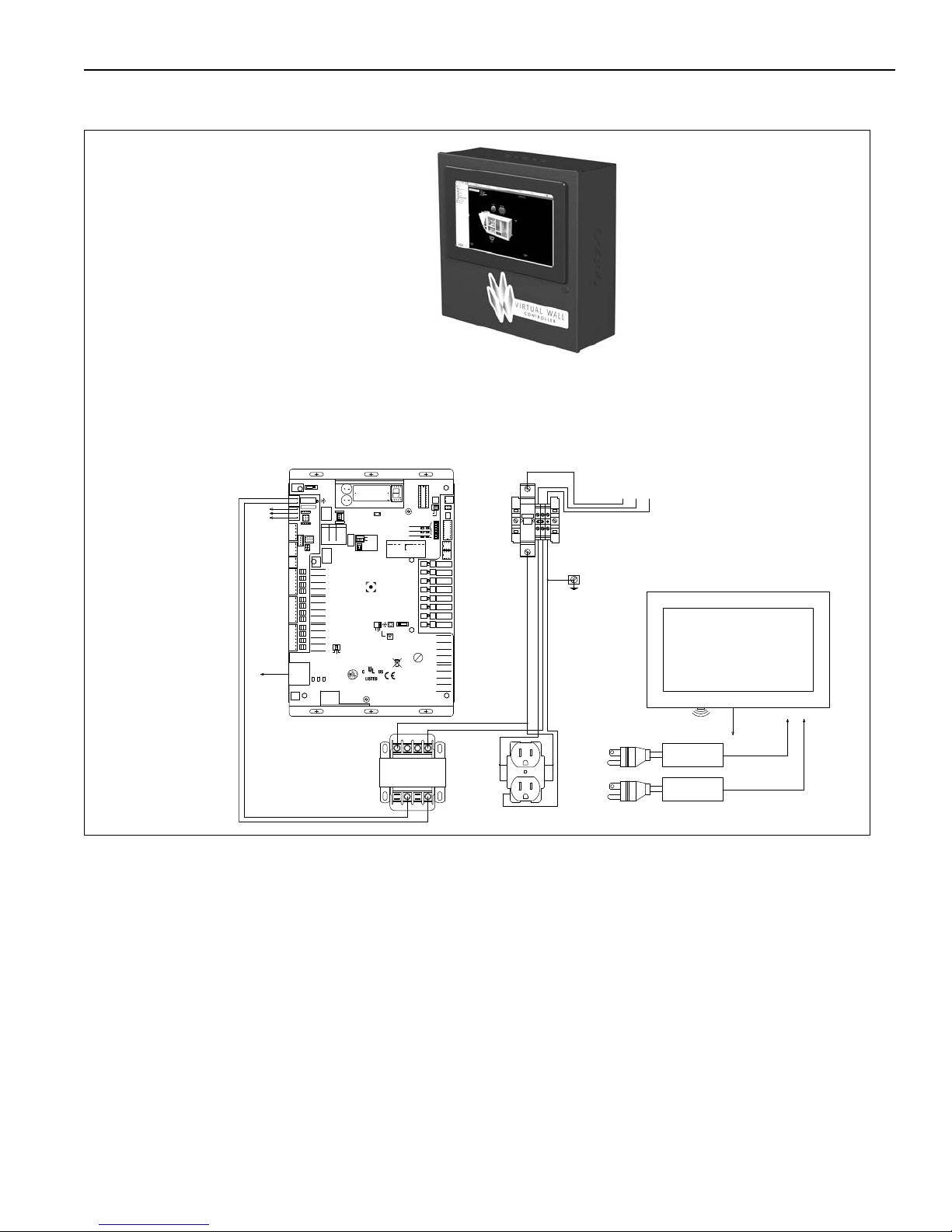
1.6 Carton Contents
N
G
24Vac
N1/Gnd
H1
H3
H2
H4
L
N
G
N
L
G
N
88F0
E143900
TYPE: 002003
Power
Off On
Power
Gnd
24Vac
Port 1
485
ARC-
Shield
Net -
Net +
156
Port 2a
Rnet
Gnd
Rnet +
Rnet +12V
Xnet +
Xnet Gnd
Xnet Expansion
Local
Rnet+
Gnd
Sense
+12V
Rnet-
Access
EIA-485
EIA-232
Thermistor/
dry-contact/
Mode Select
Universal Input
mA
RTD
Volts
10V Max, 20mA Max
Inputs: All
UI-4
UI-3
UI-2
UI-1
Gnd
+
Gnd
Gnd
+
+
Gnd
+
8
7
6
5
4
3
2
1
UI-8
Gnd
UI-6
UI-7
UI-5
Gnd
+
+
Gnd
+
Gnd
+
UI-12
UI-11
UI-10
UI-9
+
Gnd
+
Gnd
Gnd
+
Gnd
+
24 Vdc
24 Vdc
200mA maximum
Auto Off On
0-20mA
0-10Vdc
Relay
Controller
Address
1's
10's
Archive Valid
Port 2a Rx
Port 2a Tx
Port 1 Rx
Port 1 Tx
Battery low
Ext. Batt.
Int. Batt.
External
Battery
Gnd
+3V
Status
Module
3V Lithium Battery
CR-123A
0 = Download required
3 = Comm setup error
1 = Control Program Error
4 = System error
8 = Formatting
2 = RAM full
Chase = OK
Status Codes
Class 2
ONLY Use Copper
24Vac, 50VA
Without Keypad:
26Vdc, 23W, 0.9A
Outputs
24Vdc Max, 50mA Max
Format
Pot
2-wire
4-wire
2 wire4 wire
Rx -
Net-
Net+
n/c
Tx -
Tx +
Rx +n/c
EIA-232
DCD
Rx
Tx
DTR
Signal Ground
®
BACnet
Over ARCNET156 KBaud
Made in USA
Port 2a BT485
Port 1
Port 1 BT485
Conductors
2A, 50-60 Hz
Blinking Dot = 'Run'
On
Off
Enhanced
8
7
6
5
4
3
2
1
8
7
6
5
4
3
2
1
IP Addr
AssignedDefault
10/100 BaseT
Ethernet Port E1
100 LAN LINK
®
8
7
6
5
See BAS Table Below
Protocols
6
MS/TP m
MS/TP s
Off
N2 On
Lon SLTA
Off
BAUD
4
5
9600 Off Off
19.2 KOff On
38.4 KOn Off
76.8 KOn On
On
Modbus
8
Off
Off
On
On
Off
4
BACnet
3
7
Off
On
Off
Off
Off
PTP Off
Off
On
Access Port 2a
Lon Option
Off
On
On
2
1
UO-1
UO-2
UO-3
UO-4
UO-8
UO-7
UO-6
UO-5
On
Off
2
1
BAS Port
BAS Port Settings
Set Pot Full CW
24Vac
DO NOT APPLY 24Vac TO
UNIVERSAL OUTPUTS
External 24Vdc relay coil only
Brownout
3
UO-2
UO-1
2
1
UO-4
UO-3
6
5
4
7
8
6
UO-7
UO-6
UO-5
3
1
2
4
5
UO-8
7
8
+
Gnd
+
Gnd
+
Gnd
+
Gnd
+
Gnd
+
Gnd
+
Gnd
+
Gnd
Aux Power Out
Port 2b
Port 2a
IOPro812u
07/10/12
Rev 6
Open Energy
Management Equipment
26Vdc
I/O Pro 812u
CONTROLLER
CB
20A
BLK WHT GRN
L N GND
120V 60HZ
1Ø 20A
POWER IN
TO ADDITIONAL
CONTROLLERS
ETHERNET
CONNECTION TO
TOUCHSCREEN
(RJ45)
ETHERNET
CONNECTION
TO CONTROL
BOARD
WIFI CONNECTION
TO LOCAL
NETWORK
TOUCHSCREEN ADAPTER
OUTPUT: 12VDC 4.0A
COMPUTER ADAPTER
OUTPUT: 12VDC 5.0A
TOUCHSCREEN & COMPUTER
POWER IN
TRANSFORMER
VIRTUAL WALL™ Controller Installation Manual
(P/N 1010100NA)
Inside View
VIRTUAL WALL™ Controller
VWCCPXX: VIRTUAL WALL™ Controller Central Controller
SECTION 1: INTRODUCTION
3
Page 8
VIRTUAL WALL™ CONTROLLER INSTALLATION MANUAL
FIGURE 2: Example Site Layout
NOTE: Conceptual drawing, not to scale. Venting not shown.
4
Page 9

SECTION 2: SPECIFICATIONS
SECTION 2: SPECIFICATIONS
2.1 VIRTUAL WALL
™
Controller
2.1.1 Standard Enclosure
Construction: 16 gauge painted steel, hinged
door, removable knockouts
provided.
Dimensions: W x H x D
(in): 19 x 19 x 7
(cm): 48.3 x 48.3 x 17.8
To uchscreen Dimension: 15" Wide Screen
Weight: 35 lbs (15.9 kg)
2.1.2 Electrical
Power Supply: 120 V (+/- 10%) 1 Ø, 60 Hz
To uchscreen Power Supply:
Input: 120VAC, 1A, 60Hz
Output: 12VDC, 4A
CPU Power Supply:
Input: 120VAC, 1.5A, 60Hz
Output: 12VDC, 5A
or 4-wire). Network protocol selectable for BACnet
(MS/TP or PTP), Modbus, N2, LonWorks SLTA, or
modem.
Rnet port: Interface with a BACview5, BACview6, RS
sensors, ZS sensors or local laptop.
Battery: CR123A, 10 yr life, 720 cumulative hours of
power outage
NOTE: Battery for time keeping purposes and saving
trend data during power outages.
Control Board Listed by: UL-916, CE, FCC Part 15Subpart B - Class A. BTL (BACnet Test Labs) - BACnet Building Controller (B-BC)
2.2 Repeater
2.2.1 Standard Enclosure
Construction: Fabricated in accordance with UL
specifications from code gauge steel,
NEMA 1.
Finish: Austin screw cover boxes standard
construction galvanized steel with
ANSI 61 gray polyester po
wder
Universal Inputs:
Twelve Universal Inputs
0-5 Vdc
0-10 Vdc
0-20 mA
Thermister (10k ohm type II)
1K ohm RTD
Dry Contact
Universal Outputs:
0-10 Vdc
0-20 mA
Relay
HOA (hand/off/auto) switches for
all outputs
Communication Ports:
coating.
Dimensions: W x H x D
(in): 12 x 12 x 4
(cm): 30.5 x 30.5 x 10.5
2.2.2 Electrical
Power Supply: 120 V (+/- 10%) 1 Ø, 60 Hz
Por ts: RS-485 Communications Bus
RS-232 Direct Connect Bus
Port 1: Configurable for ARC156 or EIA-485 (2-wire).
Built-in support for BACnet (MS/TP or ARC156), N2,
and Modbus
Port 2a: Configurable for EIA-232 or EIA-485 (2-wire
5
Page 10
VIRTUAL WALL™ CONTROLLER INSTALLATION MANUAL
FIGURE 3: VIRTUAL WALL
™
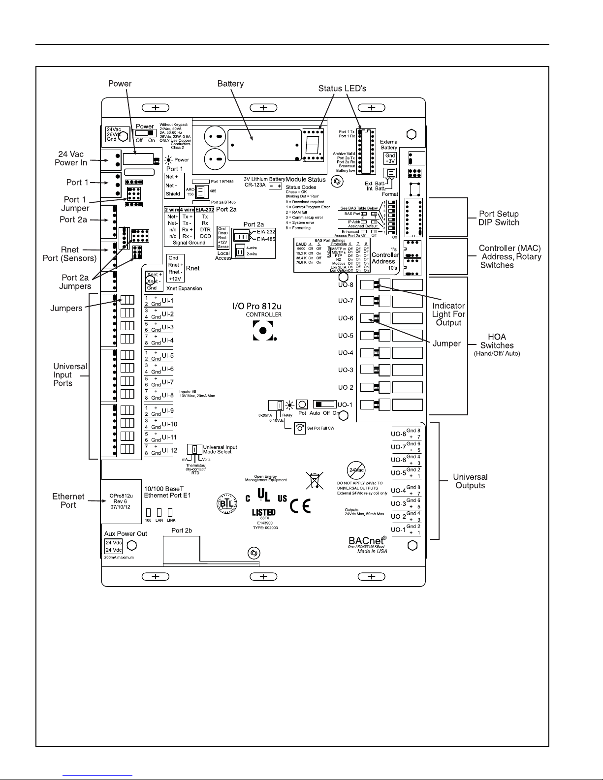
Controller Specifications
6
Page 11
SECTION 3: INSTALLATION
DANGER
Electrical Shock Hazard
Disconnect electric before service.
Controller must be properly grounded to an
electrical source.
Failure to follow these instructions can
result in death or electrical shock.
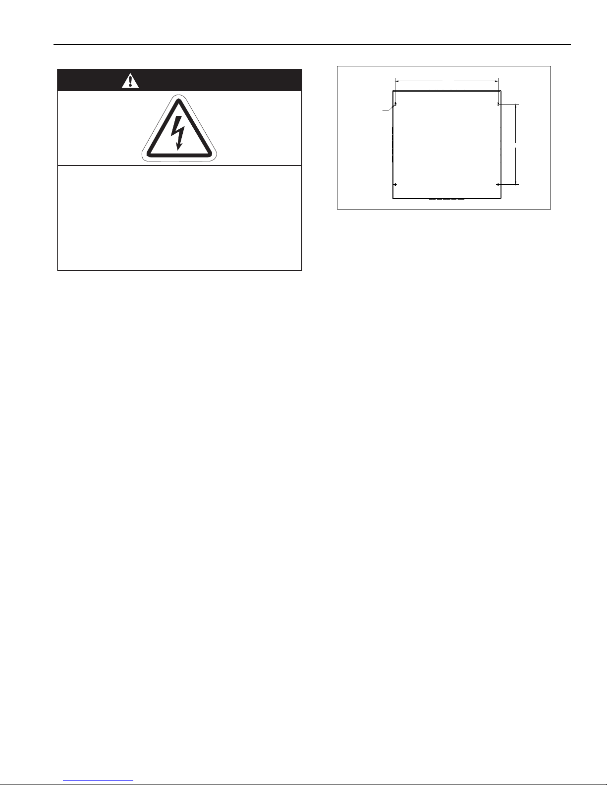
18.000
14.000
Ø
0.359
(4X)
3.1 Preparation
Before installing the controller, observe the following:
3.1.1 Ensure that you have a copy of the site layout
for the project that clearly identifies all controllers on
the network chain.
3.1.2 Familiarize yourself with the controller compo-
nents and the board diagram. See Page 10, Figure 4.
3.2 Positioning the VIRTUAL WALL™ Controller
3.2.1 Choose a mounting location for the controller.
The Virtual Wall controller may lie at any node along
the MS/TP daisy chain. For serviceability, it is conve-
nient to mount the controller at occupant level. It is
recommended to mount the controller in the vicinity
of exhaust fan and/or lighting control.
Do not mount controller outdoors. Controller must not
be installed where subjected to adverse conditions
such as: combustible, oily, or hazardous vapors or
dust; excessive moisture or dirt; v
ibration. To avoid
damage from possible drips, do not mount controller
directly beneath CORAYVAC
®
vacuum pump. Avoid
installing the controller in mezzanines, direct sunlight, or near external heat sources because these
locations usually have unpredictable temperature
rises.
Maximum length of communication wire from the first
controller to the last is 4000' (1219 m) without the use
of a repeater. A repeater is available for wire length
greater than 4000' (1219 m). See Page 14, Section
3.2.2 Position the controller at occupant level for
ease of service.
5.4.1.
SECTION 3: INSTALLATION
Recommended screw size: 1/4" - 5/16" x 2" with
washers.
3.3 Cable Requirements
3.3.1 VIRTUAL WALL™ Controller
Below is the recommended cable for the various
connections for VIRTUAL WALL™ Controller:
• Control Power Supply
The power connection should be made with cable,
size 12 AWG.
• Local Network Connection
The local connection to the network should be
made with a standard Ethernet cable
• Communications between Multiple Controllers
(MS/TP)
One twisted pair of 22 AWG minimum or equivalent
shielded high speed, low capacitance cable. Maximum network length: 4000' (1219 m) at 19.2K Baud
Rate.
3.4 Check Installation Materials
3.4.1 Control Wiring
Shielded cable: one twisted pair of stranded 22 AWG
minimum high speed, low capacitance wire is
required for MS/TP communications between controllers.
3.4.2 Programming Details
Controllers are pre-programmed. See product specific IOS manual for details.
3.4.3 Repeater
Below is the recommended cable for the various con-
nections for the repeater:
• Line Power Supply
The power connection should be made with
cable, size 18 AWG.
• RS485 Communications
One twisted pairs of 22 AWG minimum or equiva-
lent shielded cable; Belden #3105A.
7
Page 12
VIRTUAL WALL™ CONTROLLER INSTALLATION MANUAL
DANGER
Electrical Shock Hazard
Disconnect electric before service.
Controller must be properly grounded to an
electrical source.
Failure to follow these instructions can
result in death or electrical shock.
3.5 Electrical Installation Requirements of
VIRTUAL WALL™ Controller
• VIRTUAL WALL™ Controller must be feeding from a
local fused isolator for a total amperage not exceeding 20A.
8
Page 13
SECTION 4: WIRING DIAGRAM
DANGER
Electrical Shock Hazard
Disconnect electric before service.
Controller must be properly grounded to an
electrical source.
Failure to follow these instructions can
result in death or electrical shock.
SECTION 4: WIRING DIAGRAM
9
Page 14
VIRTUAL WALL™ CONTROLLER INSTALLATION MANUAL
N
G
24Vac
N1/Gnd
H1
H3
H2
H4
L
N
G
N
L
G
N
88F0
E143900
TYPE: 002003
Power
Off On
Power
Gnd
24Vac
Port 1
485
ARC-
Shield
Net -
Net +
156
Port 2a
Rnet
Gnd
Rnet +
Rnet -
+12V
Xnet +
Xnet -
Gnd
Xnet Expansion
Local
Rnet+
Gnd
Sense
+12V
Rnet-
Access
EIA-485
EIA-232
Thermistor/
dry-contact/
Mode Select
Universal Input
mA
RTD
Volts
10V Max, 20mA Max
Inputs: All
UI-4
UI-3
UI-2
UI-1
Gnd+Gnd
Gnd
+
+
Gnd
+
8765432
1
UI-8
Gnd
UI-6
UI-7
UI-5
Gnd
+
+
Gnd+Gnd
+
UI-12
UI-11
UI-10
UI-9
+
Gnd+Gnd
Gnd+Gnd
+
24 Vdc
24 Vdc
200mA maximum
Auto Off On
0-20mA
0-10Vdc
Relay
Controller
Address
1's
10's
Archive Valid
Port 2a Rx
Port 2a Tx
Port 1 Rx
Port 1 Tx
Battery low
Ext. Batt.
Int. Batt.
External
Battery
Gnd
+3V
Status
Module
3V Lithium Battery
CR-123A
0 = Download required
3 = Comm setup error
1 = Control Program Error
4 = System error
8 = Formatting
2 = RAM full
Chase = OK
Status Codes
Class 2
ONLY Use Copper
24Vac, 50VA
Without Keypad:
26Vdc, 23W, 0.9A
Outputs
24Vdc Max, 50mA Max
Format
Pot
2-wire
4-wire
2 wire4 wire
Rx -
Net-
Net+
n/c
Tx -
Tx +
Rx +n/c
EIA-232
DCD
Rx
Tx
DTR
Signal Ground
®
BACnet
Over ARCNET156 KBaud
Made in USA
Port 2a BT485
Port 1
Port 1 BT485
Conductors
2A, 50-60 Hz
Blinking Dot = 'Run'
On
Off
Enhanced
8765432
1
8765432
1
IP Addr
Assigned Default
10/100 BaseT
Ethernet Port E1
100 LAN LINK
®
876
5
See BAS Table Below
Protocols
6
MS/TP m
MS/TP s
Off
N2 On
Lon SLTA
Off
BAUD
4
5
9600 Off Off
19.2 K Off On
38.4 K On Off
76.8 K On On
On
Modbus
8
Off
Off
On
On
Off
4
BACnet
3
7
OffOnOff
Off
Off
PTP Off
Off
On
Access Port 2a
Lon Option
Off
On
On
2
1
UO-1
UO-2
UO-3
UO-4
UO-8
UO-7
UO-6
UO-5
On
Off
2
1
BAS Port
BAS Port Settings
Set Pot Full CW
24Vac
DO NOT APPLY 24Vac TO
UNIVERSAL OUTPUTS
External 24Vdc relay coil only
Brownout
3
UO-2
UO-1
2
1
UO-4
UO-3
65478
6
UO-7
UO-6
UO-5
31245
UO-8
7
8
+
Gnd+Gnd+Gnd+Gnd+Gnd+Gnd+Gnd+Gnd
Aux Power Out
Port 2b
Port 2a
IOPro812u
07/10/12
Rev 6
Open Energy
Management Equipment
26Vdc
I/O Pro 812u
CONTROLLER
CB
20A
BLK WHT GRN
L N GND
120V 60HZ
1Ø 20A
POWER IN
TO ADDITIONAL
CONTROLLERS
ETHERNET
CONNECTION TO
TOUCHSCREEN
(RJ45)
ETHERNET
CONNECTION
TO CONTROL
BOARD
WIFI CONNECTION
TO LOCAL
NETWORK
TOUCHSCREEN ADAPTER
OUTPUT: 12VDC 4.0A
COMPUTER ADAPTER
OUTPUT: 12VDC 5.0A
TOUCHSCREEN & COMPUTER
POWER IN
TRANSFORMER
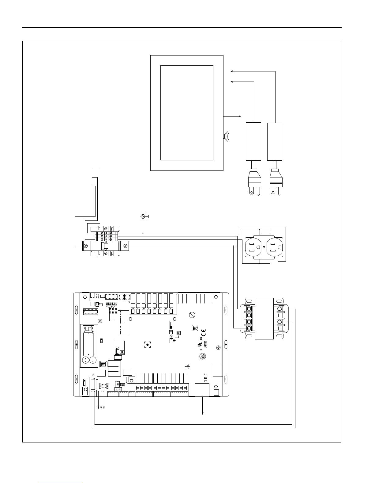
FIGURE 4: VIRTUAL WALL™ Controller Wiring Diagram
10
Page 15

SECTION 5: COMMUNICATIONS
SECTION 5: COMMUNICATIONS
When multiple SAS products are networked together,
the controllers communicate through MS/TP wiring
arranged in series from one controller to the next.
See Page 12, Figure 5
5.1 WebCTRL
®
WebCTRL® comes standard with the Virtual Wall
Controller package. This web based monitoring software allows for quick and easy control of every
device on the MS/TP network chain. Plant layout
graphics, product graphics, scheduling, alarm monitoring, parameter trending and much more are avail-
able from the comfort of a desk. Software is installed
on the touchscreen computer and connected to the
local network and all other computers are able to
gain access through this point. The Virtual Wall Controller acts as the IP connection point to the local network.See Section 6 for WebCTRL® details.
5.2 Communications Between Multiple SAS
Products
The controllers from each SAS product must have
MS/TP communications wired in series. Page 12,
Figure 5. Connect the MS/TP (Port 1) terminal on
controller #1 to the MS/TP (Port 1) terminal on controller #2 and so on in a daisy chain fashion. Shield
wires for MS/TP cables should be twisted together,
but not grounded, at all satellite controllers in daisy
chain. Ground shield wire at central panel only.
Maximum of 32 controllers in series. For communica-
tion cable requirements, see Page 7, Section 3.3
A unique MAC address is required for each controller
on the MS/TP network. Set the MAC address using
the Rotary Switches. For help locating these, see the
labeled control board diagram in Figure 3. There are
2 rotary switches. The upper rotary switch is labeled
"1's" and lower rotary switch is labeled "10's". To set
the MAC address for the first 9 controllers, the lower
rotary switch (10's) is set to "0", the upper rotary
switch (1's) is set to the appropriate controller num-
ber. To set the MAC address for controller numbers
10 and up, the setting of the lower rotary switch (10's)
must be combined with the value of the upper rotary
switch (1's). For example: To set the MAC address to
"17", adju
st the lower rotary switch (10's) to "1" and
adjust the upper rotary switch (1's) to "7".
AIR SOLUTIONS
™
independent distributor, if more
than 32 satellite controllers are required.
NOTE: The Virtual Wall Controller should be set to
"1". Changes to the rotary switches are acknowl-
edged only after the board has been power cycled.
Contact Specified Air Solutions or your SPECIFIED
11
Page 16
VIRTUAL WALL™ CONTROLLER INSTALLATION MANUAL
Archive Valid
Port 2a Rx
Port 2a Tx
Port 1 Rx
Port 1 Tx
Battery low
External
Battery
Gnd
+3V
Brownout
88F0
E143900
TYPE: 002003
Power
Off On
Power
Gnd
24Vac
485
ARC-
Shield
Net -
Net +
156
Port 2a
Rnet
Gnd
Rnet +
Rnet +12V
Xnet +
Xnet Gnd
Xnet Expansion
Local
Rnet+
Gnd
Sense
+12V
Rnet-
Access
EIA-485
EIA-232
Thermistor/
dry-contact/
Mode Select
Universal Input
mA
RTD
Volts
10V Max, 20mA Max
Inputs: All
UI-4
UI-3
UI-2
UI-1
Gnd
+
Gnd
Gnd
+
+
Gnd
+
8
7
6
5
4
3
2
1
UI-8
Gnd
UI-6
UI-7
UI-5
Gnd
+
+
Gnd
+
Gnd
+
UI-12
UI-11
UI-10
UI-9
+
Gnd
+
Gnd
Gnd
+
Gnd
+
24 Vdc
24 Vdc
200mA maximum
Auto Off On
0-20mA
0-10Vdc
Relay
Controller
Address
1's
10's
Ext. Batt.
Int. Batt.
Status
Module
3V Lithium Battery
CR-123A
0 = Download required
3 = Comm setup error
1 = Control Program Error
4 = System error
8 = Formatting
2 = RAM full
Chase = OK
Status Codes
Class 2
ONLY Use Copper
24Vac, 50VA
Without Keypad:
26Vdc, 23W, 0.9A
Outputs
24Vdc Max, 50mA Max
Format
Pot
2-wire
4-wire
2 wire4 wire
Rx -
Net-
Net+
n/c
Tx -
Tx +
Rx +n/c
EIA-232
DCD
Rx
Tx
DTR
Signal Ground
®
BACnet
Over ARCNET156 KBaud
Made in USA
Port 2a BT485
Port 1
Port 1 BT485
Conductors
2A, 50-60 Hz
Blinking Dot = 'Run'
On
Off
Enhanced
8
7
6
5
4
3
2
1
8
7
6
5
4
3
2
1
IP Addr
Assigned Default
10/100 BaseT
Ethernet Port E1
100 LAN LINK
8
7
6
5
See BAS Table Below
Protocols
6
MS/TP m
MS/TP s
Off
N2 On
Lon SLTA
Off
BAUD
4
5
9600 Off Off
19.2 K Off On
38.4 K On Off
76.8 K On On
On
Modbus
8
Off
Off
On
On
Off
4
BACnet
3
7
Off
On
Off
Off
Off
PTP Off
Off
On
Access Port 2a
Lon Option
Off
On
On
2
1
UO-1
UO-2
UO-3
UO-4
UO-8
UO-7
UO-6
UO-5
On
Off
2
1
BAS Port
BAS Port Settings
Set Pot Full CW
24Vac
DO NOT APPLY 24Vac TO
UNIVERSAL OUTPUTS
External 24Vdc relay coil only
3
UO-2
UO-1
2
1
UO-4
UO-3
6
5
4
7
8
6
UO-7
UO-6
UO-5
3
1
2
4
5
UO-8
7
8
+
Gnd
+
Gnd
+
Gnd
+
Gnd
+
Gnd
+
Gnd
+
Gnd
+
Gnd
Aux Power Out
Port 2b
Port 2a
IOPro812u
07/10/12
Rev 6
Open Energy
Management Equipment
26Vdc
I/O Pro 812u
CONTROLLER
Rotary Switches
Range 1-99
Archive Valid
Port 2a Rx
Port 2a Tx
Port 1 Rx
Port 1 Tx
Battery low
External
Battery
Gnd
+3V
Brownout
88F0
E143900
TYPE: 002003
Power
Off On
Power
Gnd
24Vac
485
ARC-
Shield
Net -
Net +
156
Port 2a
Rnet
Gnd
Rnet +
Rnet +12V
Xnet +
Xnet Gnd
Xnet Expansion
Local
Rnet+
Gnd
Sense
+12V
Rnet-
Access
EIA-485
EIA-232
Thermistor/
dry-contact/
Mode Select
Universal Input
mA
RTD
Volts
10V Max, 20mA Max
Inputs: All
UI-4
UI-3
UI-2
UI-1
Gnd
+
Gnd
Gnd
+
+
Gnd
+
8
7
6
5
4
3
2
1
UI-8
Gnd
UI-6
UI-7
UI-5
Gnd
+
+
Gnd
+
Gnd
+
UI-12
UI-11
UI-10
UI-9
+
Gnd
+
Gnd
Gnd
+
Gnd
+
24 Vdc
24 Vdc
200mA maximum
Auto Off On
0-20mA
0-10Vdc
Relay
Controller
Address
1's
10's
Ext. Batt.
Int. Batt.
Status
Module
3V Lithium Battery
CR-123A
0 = Download required
3 = Comm setup error
1 = Control Program Error
4 = System error
8 = Formatting
2 = RAM full
Chase = OK
Status Codes
Class 2
ONLY Use Copper
24Vac, 50VA
Without Keypad:
26Vdc, 23W, 0.9A
Outputs
24Vdc Max, 50mA Max
Format
Pot
2-wire
4-wire
2 wire4 wire
Rx -
Net-
Net+
n/c
Tx -
Tx +
Rx +n/c
EIA-232
DCD
Rx
Tx
DTR
Signal Ground
®
BACnet
Over ARCNET156 KBaud
Made in USA
Port 2a BT485
Port 1
Port 1 BT485
Conductors
2A, 50-60 Hz
Blinking Dot = 'Run'
On
Off
Enhanced
8
7
6
5
4
3
2
1
8
7
6
5
4
3
2
1
IP Addr
Assigned Default
10/100 BaseT
Ethernet Port E1
100 LAN LINK
8
7
6
5
See BAS Table Below
Protocols
6
MS/TP m
MS/TP s
Off
N2 On
Lon SLTA
Off
BAUD
4
5
9600 Off Off
19.2 K Off On
38.4 K On Off
76.8 K On On
On
Modbus
8
Off
Off
On
On
Off
4
BACnet
3
7
Off
On
Off
Off
Off
PTP Off
Off
On
Access Port 2a
Lon Option
Off
On
On
2
1
UO-1
UO-2
UO-3
UO-4
UO-8
UO-7
UO-6
UO-5
On
Off
2
1
BAS Port
BAS Port Settings
Set Pot Full CW
24Vac
DO NOT APPLY 24Vac TO
UNIVERSAL OUTPUTS
External 24Vdc relay coil only
3
UO-2
UO-1
2
1
UO-4
UO-3
6
5
4
7
8
6
UO-7
UO-6
UO-5
3
1
2
4
5
UO-8
7
8
+
Gnd
+
Gnd
+
Gnd
+
Gnd
+
Gnd
+
Gnd
+
Gnd
+
Gnd
Aux Power Out
Port 2b
Port 2a
IOPro812u
07/10/12
Rev 6
Open Energy
Management Equipment
26Vdc
I/O Pro 812u
CONTROLLER
Controller
Address
1's
10's
On
Off
Enhanced
IP Addr
Assigned Default
8
7
6
5
See BAS Table Below
Protocols
6
MS/TP m
MS/TP s
Off
N2 On
Lon SLTA
Off
BAUD
4
5
9600 Off Off
19.2 K Off On
38.4 K On Off
76.8 K On On
On
Modbus
8
Off
Off
On
On
Off
4
BACnet
3
7
Off
On
Off
Off
Off
PTP Off
Off
On
Access Port 2a
Lon Option
Off
On
On
2
1
On
Off
2
1
BAS Port
BAS Port Settings
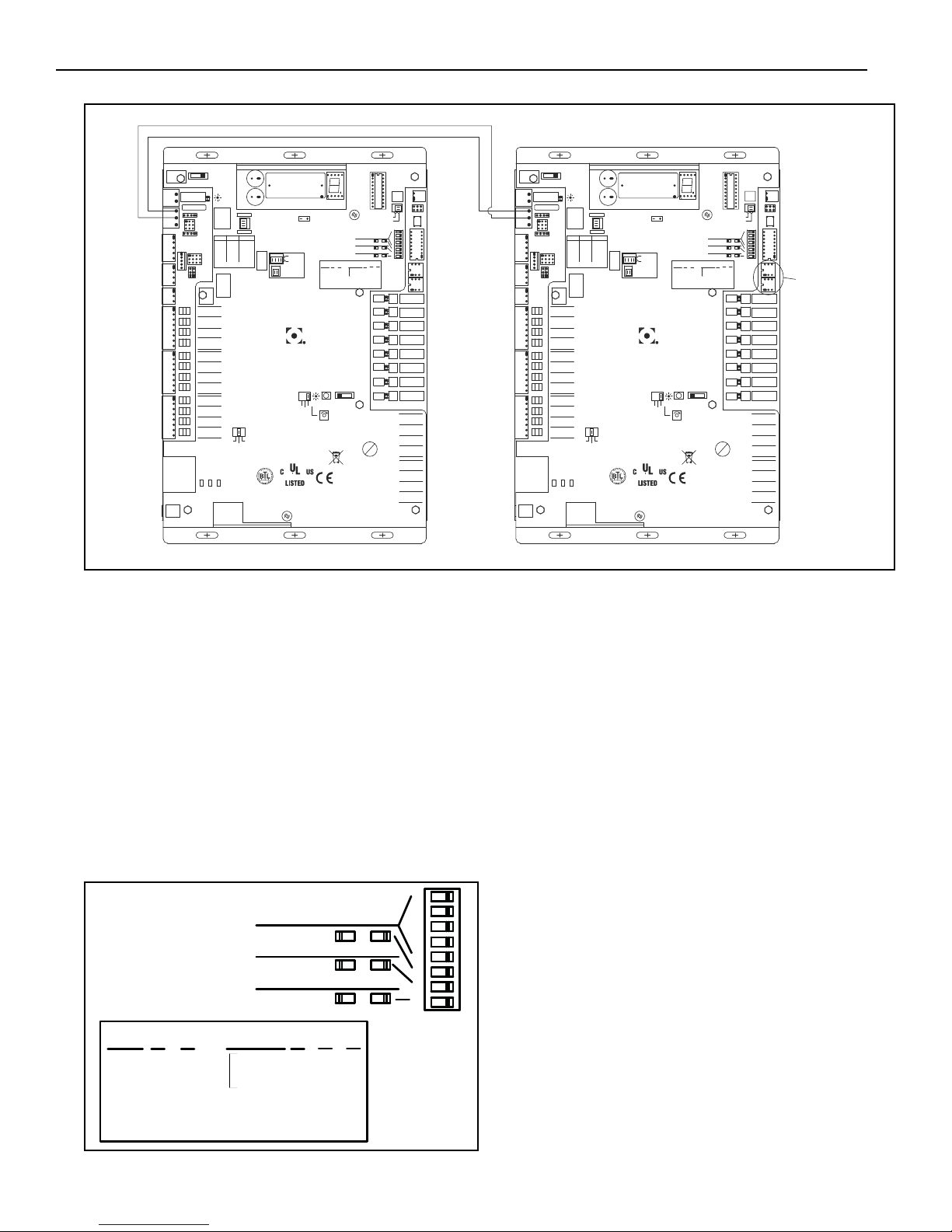
FIGURE 5: MS/TP Communications Between Controllers
5.3 Setting Baud Rate
To set the baud rate for the MS/TP network on Port 1
configure the board for a baud rate of 19.2K by setting DIP switch #5 to "ON". See chart in Figure 6 for
baud rate settings.
NOTE: Changes to the DIP switches are acknowl-
edged only after the board has been power cycled.
NOTE: Higher baud rates can be used over shorter
distances. The maximum rate of 76.8k can be used
for distances up to 2000ft (609m). A terminating
resistor is required for 76.8k. A baud rate of 38.4k
can be used without terminating resistors for distances up to approximately 3000 ft.
FIGURE 6: Setting Baud Rate
12
5.4 Control Board Setup
Universal Inputs and Outputs, Ports, Rotary Switches
and DIP switch must all be configured for the board to
work properly. Reference the labeled control board,
Figure 3, for help locating parts on the control board.
Each Input and Output has a configurable jumper.
For the Universal Inputs (UI) the jumpers are located
next to the input terminals. A diagram of the jumper
configurations is shown on the board.
For the Universal Outputs (UO) the jumpers are
located next to the HOA switches. A diagram consisting of the jumper, the indicator light, the Pot dial and
HOA switch is also shown on the board. Each HOA
switch should be set to AUTO.
Port 1 needs to be configured to operate as the BMS
port. To do this, a combination of the Port jumpers
and the DIP switch configuration is required. To
ensu
re Port 1 is operating as the BMS/BAS Port,
switch 3 of the DIP switch should be OFF. Switches
6, 7 & 8 should be configured for BACnet MS/TP
m(master) as shown in the diagram on the board.
Each should be set to OFF. Finally, the Baud Rate for
Port 1 is set using switches 4 & 5. It is important to
note that the maximum communication distance
achievable before a REPEATER is necessary is
dependent on the Baud Rate. A maximum Baud Rate
of 19.2 K can be used for distances up to 4000 ft
(1219 m). If the maximum Baud Rate of the Port is
Page 17

used, 76.8 K, a REPEATER is required after 2000 ft
(609 m) and terminating resistors put in line. Set
switch 4 to OFF and switch 5 to ON for 19.2K. DIP
switch set up is complete. Only switch 5 should be
ON. Lastly locate the Port 1 jumper. This should be
set to 485.
SECTION 5: COMMUNICATIONS
13
Page 18

VIRTUAL WALL™ CONTROLLER INSTALLATION MANUAL
®
Archive Valid
Port 2a Rx
Port 2a Tx
Port 1 Rx
Port 1 Tx
Battery low
External
Battery
Gnd
+3V
Brownout
88F0
E143900
TYPE: 002003
Power
Off On
Power
Gnd
24Vac
485
ARC-
Shield
Net -
Net +
156
Port 2a
Rnet
Gnd
Rnet +
Rnet -
+12V
Xnet +
Xnet Gnd
Xnet Expansion
Local
Rnet+
Gnd
Sense
+12V
Rnet-
Access
EIA-485
EIA-232
Thermistor/
dry-contact/
Mode Select
Universal Input
mA
RTD
Volts
10V Max, 20mA Max
Inputs: All
UI-4
UI-3
UI-2
UI-1
Gnd
+
Gnd
Gnd
+
+
Gnd
+
8
7
6
5
4
3
2
1
UI-8
Gnd
UI-6
UI-7
UI-5
Gnd
+
+
Gnd
+
Gnd
+
UI-12
UI-11
UI-10
UI-9
+
Gnd
+
Gnd
Gnd
+
Gnd
+
24 Vdc
24 Vdc
200mA maximum
Auto Off On
0-20mA
0-10Vdc
Relay
Controller
Address
1's
10's
Ext. Batt.
Int. Batt.
Status
Module
3V Lithium Battery
CR-123A
0 = Download required
3 = Comm setup error
1 = Control Program Error
4 = System error
8 = Formatting
2 = RAM full
Chase = OK
Status Codes
Class 2
ONLY Use Copper
24Vac, 50VA
Without Keypad:
26Vdc, 23W, 0.9A
Outputs
24Vdc Max, 50mA Max
Format
Pot
2-wire
4-wire
2 wire4 wire
Rx -
Net-
Net+
n/c
Tx -
Tx +
Rx +n/c
EIA-232
DCD
Rx
Tx
DTR
Signal Ground
®
BACnet
Over ARCNET156 KBaud
Made in USA
Port 2a BT485
Port 1
Port 1 BT485
Conductors
2A, 50-60 Hz
Blinking Dot = 'Run'
On
Off
Enhanced
8
7
6
5
4
3
2
1
8
7
6
5
4
3
2
1
IP Addr
AssignedDefault
10/100 BaseT
Ethernet Port E1
100 LAN LINK
8
7
6
5
See BAS Table Below
Protocols
6
MS/TP m
MS/TP s
Off
N2 On
Lon SLTA
Off
BAUD
4
5
9600 Off Off
19.2 K Off On
38.4 K On Off
76.8 K On On
On
Modbus
8
Off
Off
On
On
Off
4
BACnet
3
7
Off
On
Off
Off
Off
PTP Off
Off
On
Access Port 2a
Lon Option
Off
On
On
2
1
UO-1
UO-2
UO-3
UO-4
UO-8
UO-7
UO-6
UO-5
On
Off
2
1
BAS Port
BAS Port Settings
Set Pot Full CW
24Vac
DO NOT APPLY 24Vac TO
UNIVERSAL OUTPUTS
External 24Vdc relay coil only
3
UO-2
UO-1
2
1
UO-4
UO-3
6
5
4
7
8
6
UO-7
UO-6
UO-5
3
1
2
4
5
UO-8
7
8
+
Gnd
+
Gnd
+
Gnd
+
Gnd
+
Gnd
+
Gnd
+
Gnd
+
Gnd
Aux Power Out
Port 2b
Port 2a
IOPro812u
07/10/12
Rev 6
Open Energy
Management Equipment
26Vdc
I/O Pro 812u
CONTROLLER
®
Archive Valid
Port 2a Rx
Port 2a Tx
Port 1 Rx
Port 1 Tx
Battery low
External
Battery
Gnd
+3V
Brownout
88F0
E143900
TYPE: 002003
Power
Off On
Power
Gnd
24Vac
485
ARC-
Shield
Net -
Net +
156
Port 2a
Rnet
Gnd
Rnet +
Rnet +12V
Xnet +
Xnet Gnd
Xnet Expansion
Local
Rnet+
Gnd
Sense
+12V
Rnet-
Access
EIA-485
EIA-232
Thermistor/
dry-contact/
Mode Select
Universal Input
mA
RTD
Volts
10V Max, 20mA Max
Inputs: All
UI-4
UI-3
UI-2
UI-1
Gnd
+
Gnd
Gnd
+
+
Gnd
+
8
7
6
5
4
3
2
1
UI-8
Gnd
UI-6
UI-7
UI-5
Gnd
+
+
Gnd
+
Gnd
+
UI-12
UI-11
UI-10
UI-9
+
Gnd
+
Gnd
Gnd
+
Gnd
+
24 Vdc
24 Vdc
200mA maximum
Auto Off On
0-20mA
0-10Vdc
Relay
Controller
Address
1's
10's
Ext. Batt.
Int. Batt.
Status
Module
3V Lithium Battery
CR-123A
0 = Download required
3 = Comm setup error
1 = Control Program Error
4 = System error
8 = Formatting
2 = RAM full
Chase = OK
Status Codes
Class 2
ONLY Use Copper
24Vac, 50VA
Without Keypad:
26Vdc, 23W, 0.9A
Outputs
24Vdc Max, 50mA Max
Format
Pot
2-wire
4-wire
2 wire4 wire
Rx -
Net-
Net+
n/c
Tx -
Tx +
Rx +n/c
EIA-232
DCD
Rx
Tx
DTR
Signal Ground
®
BACnet
Over ARCNET156 KBaud
Made in USA
Port 2a BT485
Port 1
Port 1 BT485
Conductors
2A, 50-60 Hz
Blinking Dot = 'Run'
On
Off
Enhanced
8
7
6
5
4
3
2
1
8
7
6
5
4
3
2
1
IP Addr
AssignedDefault
10/100 BaseT
Ethernet Port E1
100 LAN LINK
8
7
6
5
See BAS Table Below
Protocols
6
MS/TP m
MS/TP s
Off
N2 On
Lon SLTA
Off
BAUD
4
5
9600 Off Off
19.2 K Off On
38.4 K On Off
76.8 K On On
On
Modbus
8
Off
Off
On
On
Off
4
BACnet
3
7
Off
On
Off
Off
Off
PTP Off
Off
On
Access Port 2a
Lon Option
Off
On
On
2
1
UO-1
UO-2
UO-3
UO-4
UO-8
UO-7
UO-6
UO-5
On
Off
2
1
BAS Port
BAS Port Settings
Set Pot Full CW
24Vac
DO NOT APPLY 24Vac TO
UNIVERSAL OUTPUTS
External 24Vdc relay coil only
3
UO-2
UO-1
2
1
UO-4
UO-3
6
5
4
7
8
6
UO-7
UO-6
UO-5
3
1
2
4
5
UO-8
7
8
+
Gnd
+
Gnd
+
Gnd
+
Gnd
+
Gnd
+
Gnd
+
Gnd
+
Gnd
Aux Power Out
Port 2b
Port 2a
IOPro812u
07/10/12
Rev 6
Open Energy
Management Equipment
26Vdc
I/O Pro 812u
CONTROLLER
Description Part Number
Repeater URVRP
5.4.1 Repeater
If the MS/TP communications wire length is above 4000' (1219 m), a repeater must be used to extend the
signal. The repeater can also be used to install in different methods:
• To extend communications beyond the standard 4000' (1219 m) limitation. See Page 14, Figure 7.
• To add parallel branches of VIRTUAL WALL
™
Controller communications bus wiring.
See Page 15, Figure 8.
NOTE: The maximum number of VIRTUAL WALL
™
Controllers that can be installed is 32.
FIGURE 7: Repeater External Wiring
14
Page 19
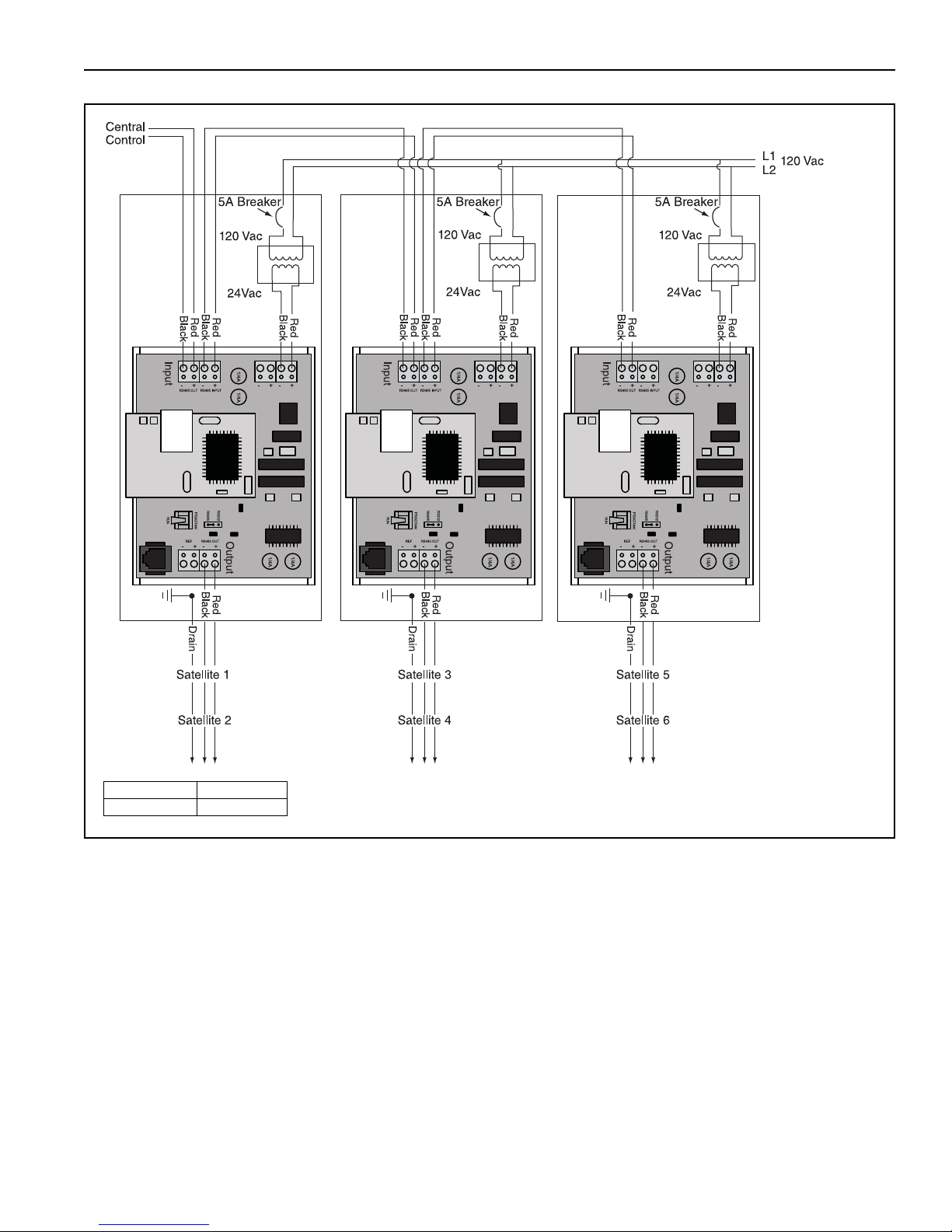
FIGURE 8: Repeater Communication Wiring Between Multiple Controllers
Description Part Number
Repeater URVRP
SECTION 5: COMMUNICATIONS
5.5 Sequence of Operations
All control equipment shall operate in stand-alone mode according to its sequence of operation in the
absence of the Virtual Wall Controller.
Occupancy
WebCTRL® shall centrally coordinate the monitoring and control of all equipment. WebCTRL® allows the
user to create plant wide schedules, trend graphs, and reports as well as adjust heating setpoints, pressure
control, cooling and more.
In the unoccupied mode, the Exhaust Fans (EF) and Outside Air Handling Unit (OAHU) shall be off. The
Infrared Heating equipment (IRH) will maintain unoccupied heating setpoints.
A predictive, learning, optimal start routine shall start the Infrared Heating equipment to achieve the target
occupancy setpoint by the start of occupancy.
In the occupied mode, the OAHU shall be cycled on and operate according to its sequence of operation. The
EF's shall be enabled and will operate according to the exhaust fan control routines outlined below.
15
Page 20

VIRTUAL WALL™ CONTROLLER INSTALLATION MANUAL
IRH and OAHU Setpoint Coordination
The IRH shall maintain the space temperature heating setpoint (occupied and unoccupied) according to its
sequence of operations as performed by the IRH controller.
Should the IRH be operating at 100% capacity and not be able to achieve or maintain the space temperature
heating setpoint after the prescribed adjustable runtime (15 min), the discharge air temperature setpoint of
the OAHU shall be raised to supplement the heating capacity of the IRH system. Once the heating setpoints
are achieved, the OAHU shall return to normal operation.
Building Pressure
In the occupied mode, the OAHU shall maintain the space at the higher of:
1. A positive pressure of 0.01" wc (adjustable) relative to the outside static pressure.
2. The required outside air CFM as measured by the equipment and defined by code or process
requirements.
Unoccupied Free Cooling
In the cooling season, if the night time outside air conditions are suitable and the OA temperature is at least
3°F lo
wer than the space temperature, the OAHU shall be switched on to pre-cool the space.
Preoccupancy Purge
If desired, the system can perform a pre-occupancy purge by staging on the EF's and OAHU prior to the start
of occupancy by a user adjustable time period to ensure sufficient air change. Outside air temperature limits
shall be provided to prevent the purge operation during times when the OA conditions are unsuitable.
Exhaust Fan Control
In the occupied mode, Exhaust Fans shall be enabled and cycle on according to one or more of the following
conditions:
1. Continuous during the occupied mode
2. Upon a rise in space temperature above the cooling setpoint
16
Page 21
SECTION 6: WEBCTRL®
SECTION 6: WEBCTRL®
The Virtual Wall touchscreen comes pre-programmed with WebCTRL® software. The touchscreen, therefore, acts as the WebCTRL® server. Launch an Internet browser and type “localhost” in the address bar to
begin. Initial login information:
User Name: administrator
Password: admin
6.1 Touchscreen Gestures
When using the Virtual Wall touchscreen, certain gestures are required to replace keyboard functionality.
The use of a stylus is recommended.
A virtual keyboard can be brought up by clicking in a desired field you wish to type in. A keyboard icon will
appear. Click this icon to open the keyboard. To open the keyboard at any time, swipe at the far right edge of
the screen. A keyboard tab will appear. Tap this tab to open the keyboard.
Use the F11 key to show/hide the Internet
browser button. Note that the forward and back buttons on the
Internet browser bar should not be used to navigate within WebCTRL®. Use the back button in WebCTRL®
located at the top next to the Action Buttons.
To open the right mouse button menu, tap and hold the screen. A loading circle will appear and the menu will
open.
6.2 Navigating
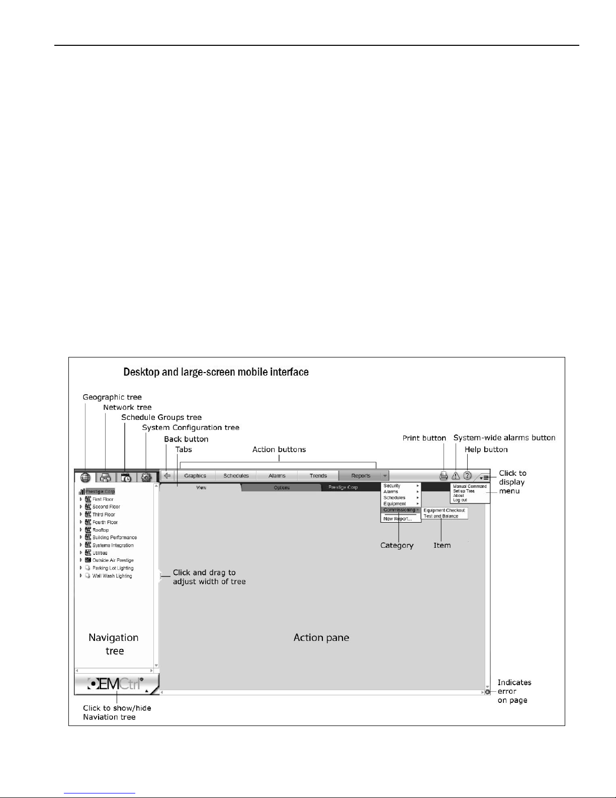
The figure above shows a breakdown of the WebCTRL® interface. Familiarize yourself with the terminology
shown. The primary functions of WebCTRL® for the end user will be within the Geographic Tree and Action
17
Page 22
VIRTUAL WALL™ CONTROLLER INSTALLATION MANUAL
buttons. The Schedule Groups and System Configuration trees are used for system setup. The
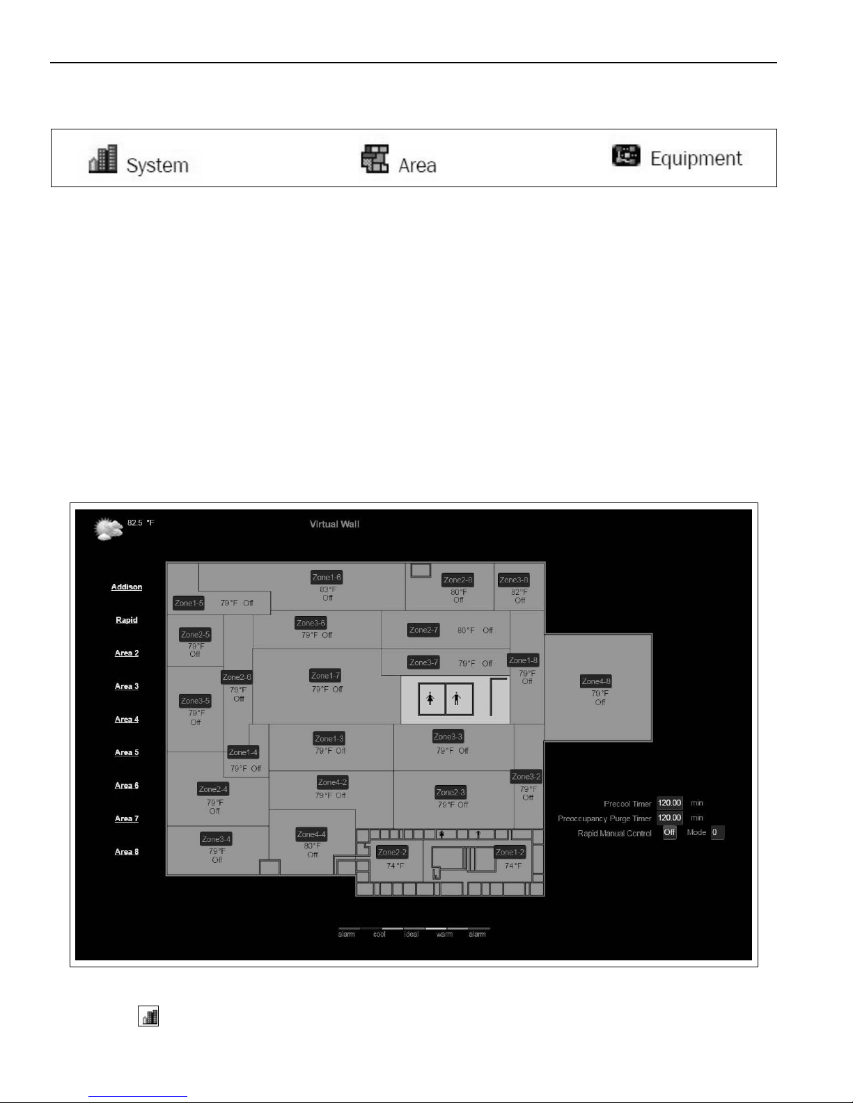
Geographic tree displays the hierarchy of equipment within the facility. Three main icons exist to denote the
type of object.
To perform an Action, select an object within the Geographic tree and then a desired action. Depending on
the object selected, different actions may be available.
Always refer to the Help button in the top right of the screen for additional information if needed. The help
button brings up a new web page with information relative to what is populated within your Action Pane.
In addition, always use the back button within the WebCTRL® interface and not the forward/back buttons on
the internet browser bar.
6.3 Graphics
Real time graphics display the c
urrent status of equipment and parameters. The graphic represents burners
firing, fan on/off status, setpoints, occupancy and more. A custom, interactive plant layout graphic is included
with the Virtual Wall system. This graphic displays the comfort level within each zone of the plant as well as
a link to specific area graphics. Color coding of zones is relative to the setpoint; therefore, multiple regions of
the same color may be different temperatures. See the figure below.
The plant layout graphic is an example of the top-level user interface. This graphic is associated with the
System (i.e. ) within the Geographic tree. The building is divided into Areas and each area further
broken down into Zones. Depicted above is each zone within the building. The name of each zone can be
18
Page 23
SECTION 6: WEBCTRL®
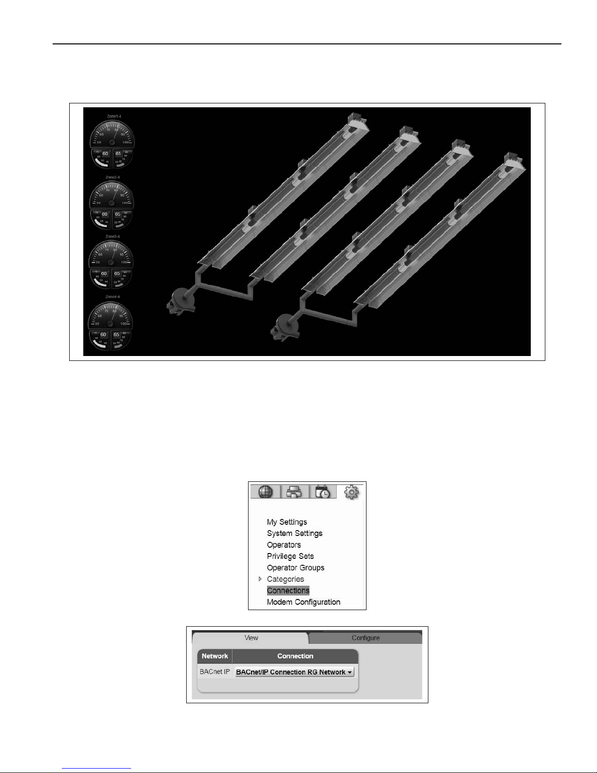
adjusted as desired. Along the left are links to the various Areas within the plant. These links take the user to
the relevant HVAC equipment graphic. The Roberts Gordon graphic is shown below.
These live graphics depict equipment operation. The Roberts Gordon graphic displays pumps spinning
when they are on and flames when the burners are lit. Interactive gauges along the left display zone
temperatures and occupied/unoccupied setpoints. The Roberts Gordon graphic also builds itself to reflect
the pump to zone configuration and the number of zones relative to the specific area. This is setup by the
user during start up.
6.4 Managing Connections
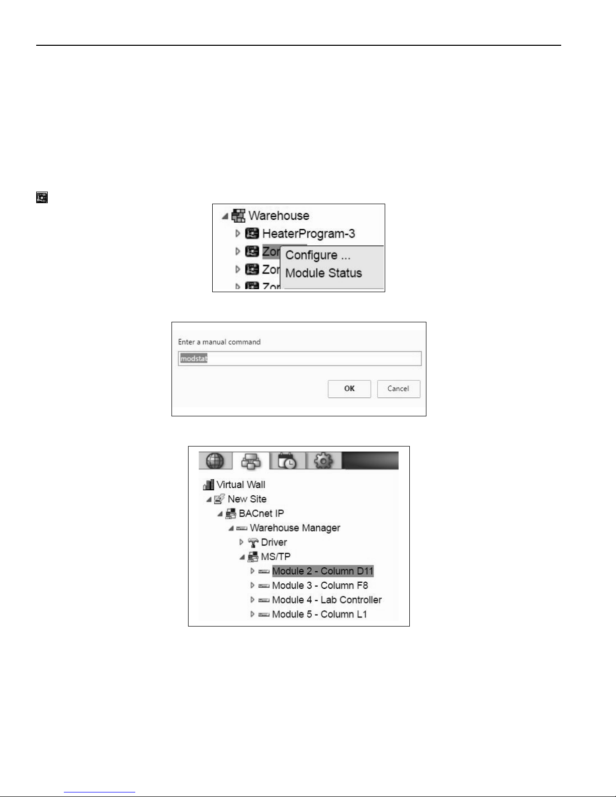
Navigate to the System Configuration tab within the Navigation Tree and select Connections
.
The View and Configure tabs are used for managing connections.
To s e t up a new connection select Add under the Configure tab. For the Virtual Wall, a new BACnet/IP con-
nection is required. Select this as the type and input the Server IP Address and Server IP Subnet Mask.
19
Page 24
VIRTUAL WALL™ CONTROLLER INSTALLATION MANUAL
Click Accept. (The touchscreen computer acts as the server)
Return to the View tab and select the desired connection from the drop down menu. Back in the Configure
tab, highlight the same connection and click Start
6.5 Miscellaneous Actions
6.5.1 Module status
Checking the module status is important for troubleshooting purposes. This check provides information
about the control board within the unit. It is also a quick way to check for communications with the unit. There
are multiple ways to check module status. Return to Geographic Tree. Select a piece of equipment (symbol
) associated with the desired control board. Right click the piece of equipment and click Module Status.
Alternatively, with the piece of equipment selected, press CTRL + M. A manual command w
indow appears.
Type modstat and click OK.
Lastly, expand the Network tree until the modules are shown under the MS/TP network. Select a unit and
again use either the right mouse button menu or the manual command window to check the module status.
6.5.2 Global Modify
The number of programs to manage within the Virtual Wall system can be quite large. Instead of going into
each program to modify the same parameter, global modify is a tool which allows the user to modify a program's parameter across all instances of that program. A good example for this tool is setpoint modification.
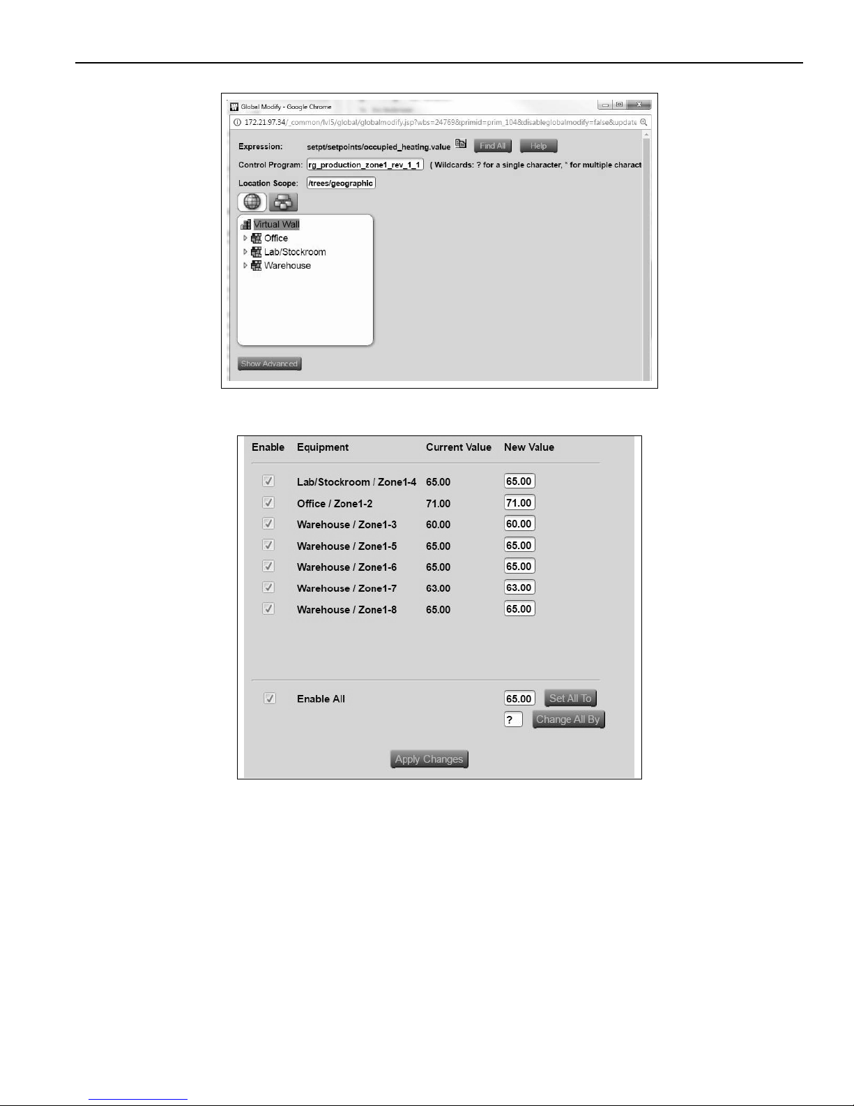
To modify the occupied heating setpoint across many zones/areas, alt + click the value. An additional set-
point window appears. Again, alt + click the occupied heating setpoint value. A global modify window pops
20
Page 25
up:
Click Find All.
SECTION 6: WEBCTRL®
In this example, WebCTRL® finds instances of this parameter across all zone 1 programs. Enter each New
Value individually if different values are desired or enter one value at the bottom and click Set All To. Apply
Changes before closing the window.
Repeat this process for zones 2, 3, & 4 if desired.
6.6 User Login & Operator Access
Privileges control which parts of the WebCTRL® system an operator can access. Privileges also control what
actions an operator can perform and what they can change. In this section creating user logins and
assigning privilege sets will be discussed.
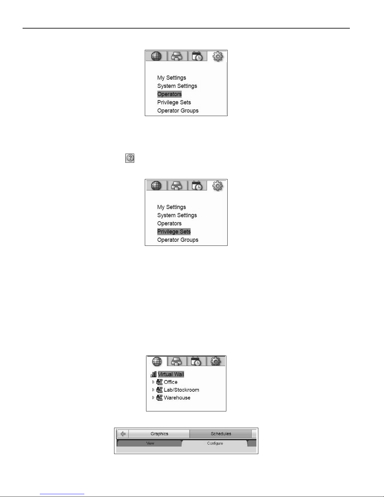
To add operators to the system, first create a user login. To do this, navigate to the System Configuration
tab in the left-hand pane and select Operators. Click Add to enter a new operator (or select an operator to
21
Page 26
VIRTUAL WALL™ CONTROLLER INSTALLATION MANUAL
edit settings later). Fill in the login information, and Personal Information if desired. Select a Privilege Set for
the operator and Accept when finished.
6.6.1 Creating Privilege Sets
Creating custom privilege sets is a useful tool when many operators of various positions want access to
WebCTRL®. To create a new privilege set, navigate to System Configuration in the left-hand pane. Select
Privilege Sets and Add. Enter a name for the set and check boxes for all privileges desired. For an
explanation of each item click the in the top right while in this Privilege Sets screen. Accept to finish and
save when complete.
6.7 Scheduling
Using WebCTRL®, plant wide schedules can be easily created. The Geographic tree, along with the
Scheduling action button, is used to accomplish this. For areas which require a schedule different from the
top lev
el plant schedule, local modifications can be made. It is recommended to create a plant wide schedule
and add or override to areas which differ.
Three Priorities exist for scheduling: Normal, Holiday and Override
Normal: Typ i ca l o c c upied period
Holiday: An unoccupied period that overrides a Normal schedule
Override: An occupied period that overrides a Holiday schedule
Several Types of schedules exist including: Weekly, Date, Date Range, Date List, Wildcard, Continuous, and
Dated Weekly.
To create a plant wide schedule, first select the top level system within the Geographic tree next to the
building icon.
Next, select Schedules tab along the top menu bar and then Configure tab on the sub menu.
22
Page 27
SECTION 6: WEBCTRL®
Click Add to create new schedule and more options appear below. Select a Priority and Type, then fill in all
appropriate fields. To finish, click Accept at the top of the screen.
The schedule has been added to all areas beneath the top level system.
6.7.1 Modify Schedules
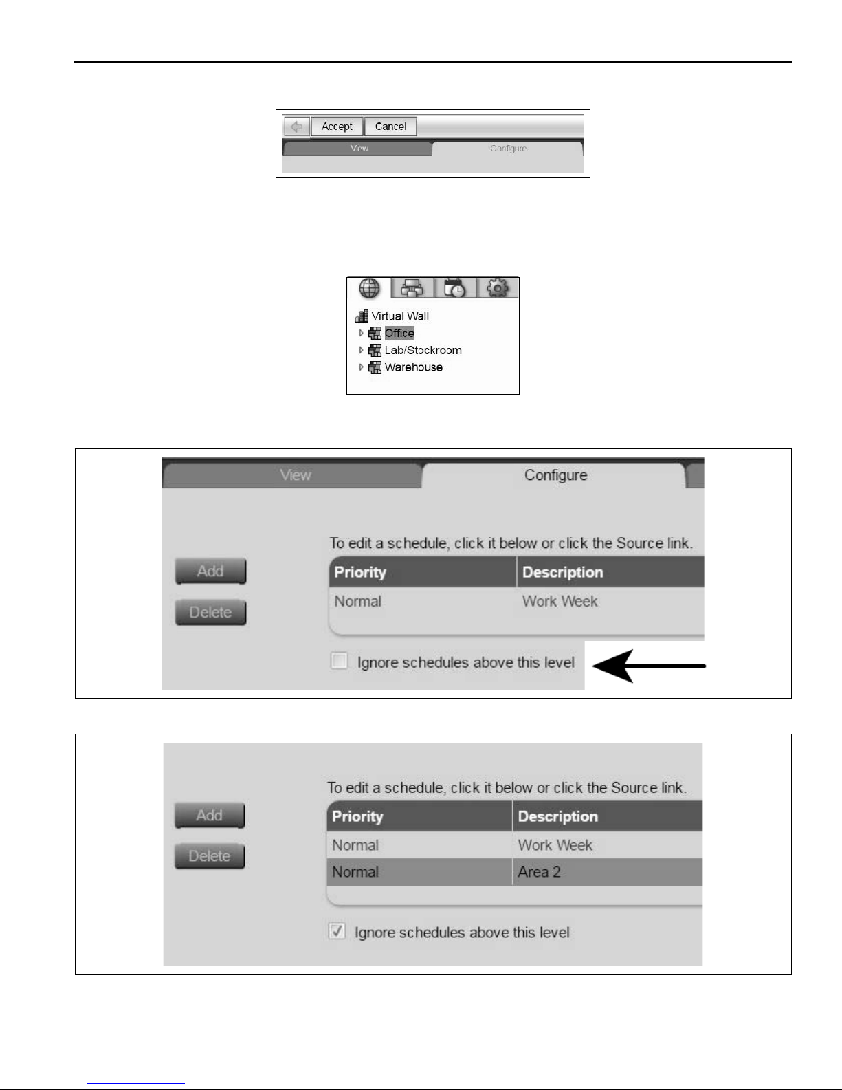
To Add/Modify schedules for specific areas, select area in Geographic tree, then Schedules and Configure
tab. A local modification to the office area is shown below.
Two options exist for creating area specific schedules. Supplemental schedules can be added to the plant
wide schedule, or a new schedule can be created and the plant wide suppressed using the Ignore
schedules above this level feature.
To use this feature, Add a new schedule to the local area in the Geographic Tree. Once created, select
schedule from the list and check the box for Ignore Schedule above.
Once the change has been accepted, the Work Week schedule depicted above will be ignored and only the
Area 2 schedule applied.
Accept this change.
23
Page 28
VIRTUAL WALL™ CONTROLLER INSTALLATION MANUAL
Supplementing the Plant Wide Schedule
For areas which are occupied beyond the plant wide schedule, add additional Normal priority schedules.
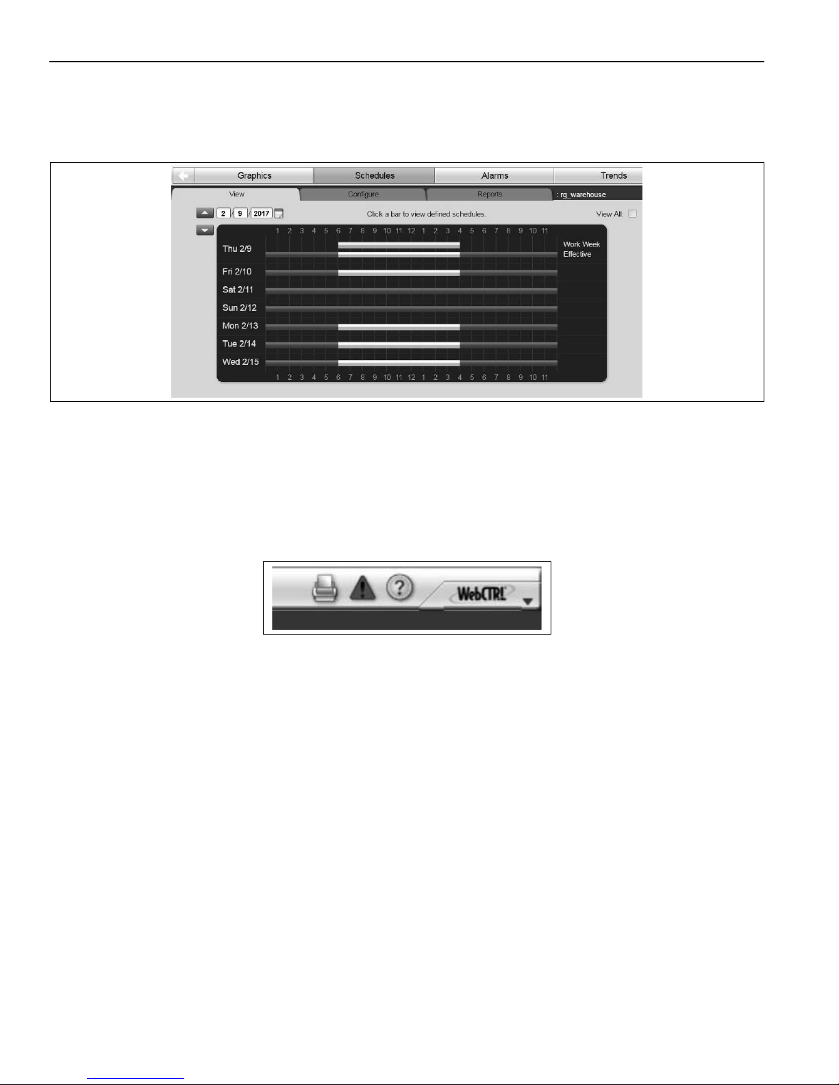
Overlapping Normal priority schedules result in occupied time beginning and ending at the most extreme
values from either one. Use the View tab shown below to check the effective occupied times after creating a
schedule.
For areas which are occupied less than the plant wide schedule, a Holiday schedule, type Dated Weekly
can be created. For example, if the plant wide schedule is 6 am - 4pm, but an area is unoccupied until 7am,
add a Holiday Dated Weekly schedule from 6 - 7am for applicable days of the week. Select an End Date far
into the future (i.e. 20 yrs) and Accept the schedule. An effective occupied time from 7am - 4 pm is the net
lt.
resu
For additional help scheduling, while under the Schedules, Configure tab, click the question mark at the top
right of the screen.
Note: Do not include preheating time in your schedules. Optimal Start automatically calculates and controls
precise preheating routines. See Modulating Controls Manual for details.
6.7.2 Schedule Groups
The Schedule Groups feature is a convenient way to apply schedules to multiple areas at once. For example,
if a group of workers are coming in on Saturday and only the stock room, shipping department and assembly
areas will be occupied, create a schedule group with these areas and then apply one schedule to meet this
need.
To create a group, on the Schedule Groups tree in the left hand pane, select Scheduling Groups. Within
the Action pane, on the right, click Add Group. Type a name for the new schedule group in the name field.
Optional: type a new reference name for the group. Note, all grou
Click Accept. Click Add Members to Group. On the Members action button, select areas or equipment to
add to the group from the tree on the right. Click Add, then Accept when finished adding. Next to the
Members action button, select the Schedules action button, then the Configure tab. Create a schedule as
previously described. When multiple Scheduling Groups exist, ensure the desired group is selected in the
left-hand tree before proceeding.
Note: Do not include preheating time in your schedules. Optimal Start automatically calculates and controls
precise preheating routines. See Modulating Controls Manual for details.
24
ps must have a unique reference name.
Page 29
SECTION 6: WEBCTRL®
6.8 Trending
The WebCTRL® system can read and store data from equipment over time and display this information in a
trend graph for monitoring purposes. Trend data can be collected from many points within the equipment.
Data is initially stored within the controller itself, however, the controller has limited memory. Historical
trending can be set up to archive data periodically to the WebCTRL® database, which is external to the
controllers.
Setting up custom trend graphs results in a quick and simple way to monitor equipment performance,
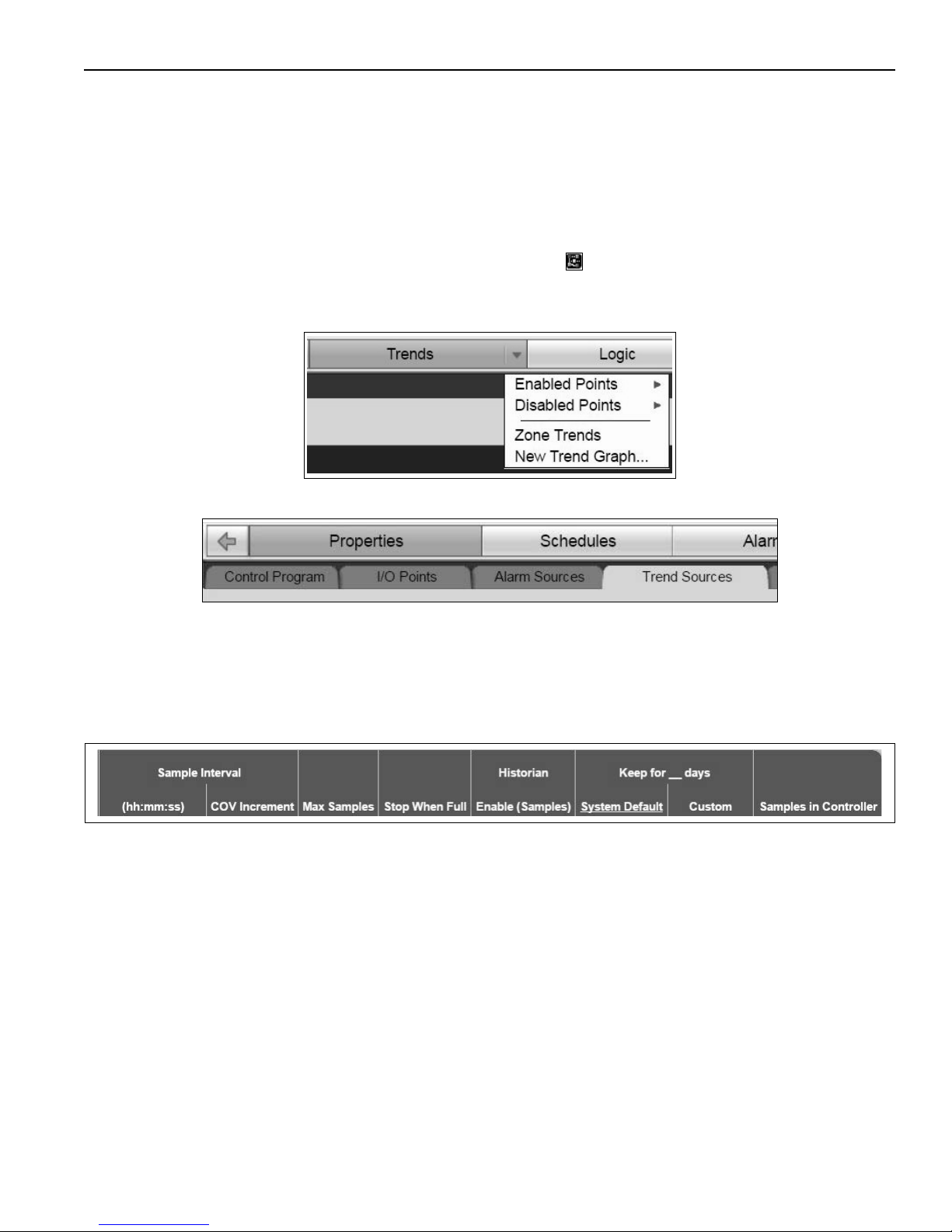
optimize the system and catch glitches. To begin creating custom graphs, first view points which are enabled
for trending. To do this, select a piece of equipment (object icon ) within the Geographic tree. Examples
of equipment are the Roberts Gordon Heater and Zone programs, or the Rapid program. From here, select
the dropdown menu on the Trend button and hover over Enabled Points. This displays all points which have
been setup for trending purposes.
With the piece of equipment selected under the Geographic tree, quickly configure all trend points within a
piece of equipment using the Trend Sources tab beneath the Properties action button.
Under the Trend Sources tab, user may want to change the Sample Interval of a point or the length of time
data is kept for. It is not recommended to change the number of samples under Max Samples or Historian.
Max samples refers to the number of samples that are stored locally on the controller. When the max is
reached, the controller overwrites locally stored data. When the number of samples under the Historian is
reached, the controller archives this data to the database (external to the controller). The number of samples
under the Historian should always be less than the max. Ensure the historian is Enabled.
The Sample Interval describes how
frequently data is collected for a trending point. Some points it is helpful
to sample upon change of value (COV). This keeps data collection to a minimum. Some parameters are
better sampled on a consistent time interval. User may set up these points as desired, but it is recommended
to leave them at factory default. User should decide how long they wish to keep Historian data. This is done
with Keep for __ days.
25
Page 30
VIRTUAL WALL™ CONTROLLER INSTALLATION MANUAL
6.8.1 Creating a Custom Trend Graph
A custom trend graph can be created for individual pieces of equipment, areas, etc. In the Geographic tree,
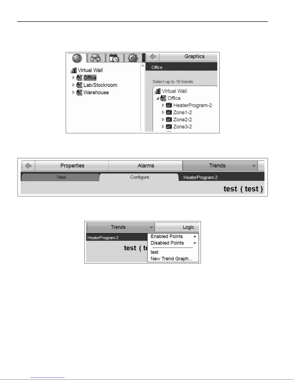
select the area or equipment where you wish to see the graph. On the Trends action button click the
dropdown menu and New Trend Graph. The Action Pane populates with a blank display and a new tree.
Select enabled points within the tree to add them to the plot. Hold CTRL to make multiple selections. Choose
at least 1 point and then Save the plot. Further configuration can be done after saving. Enter a name for the
plot and let the reference name auto generate. Click OK. After saving you are taken to the View tab. The
name of the plot appears near the top of the Action Pane (i.e. test).
The trend graph is associated with the equipment or area selected upon creation. To navigate back to the
plot at a later date, select the appropriate object in the Geog
raphic tree, click the Trends dropdown menu
and select desired plot (i.e. test).
6.8.2 Configuring a Trend Graph
With the desired equipment/area selected in the Geographic tree, navigate to the plot and the
TrendsConfigure tab.
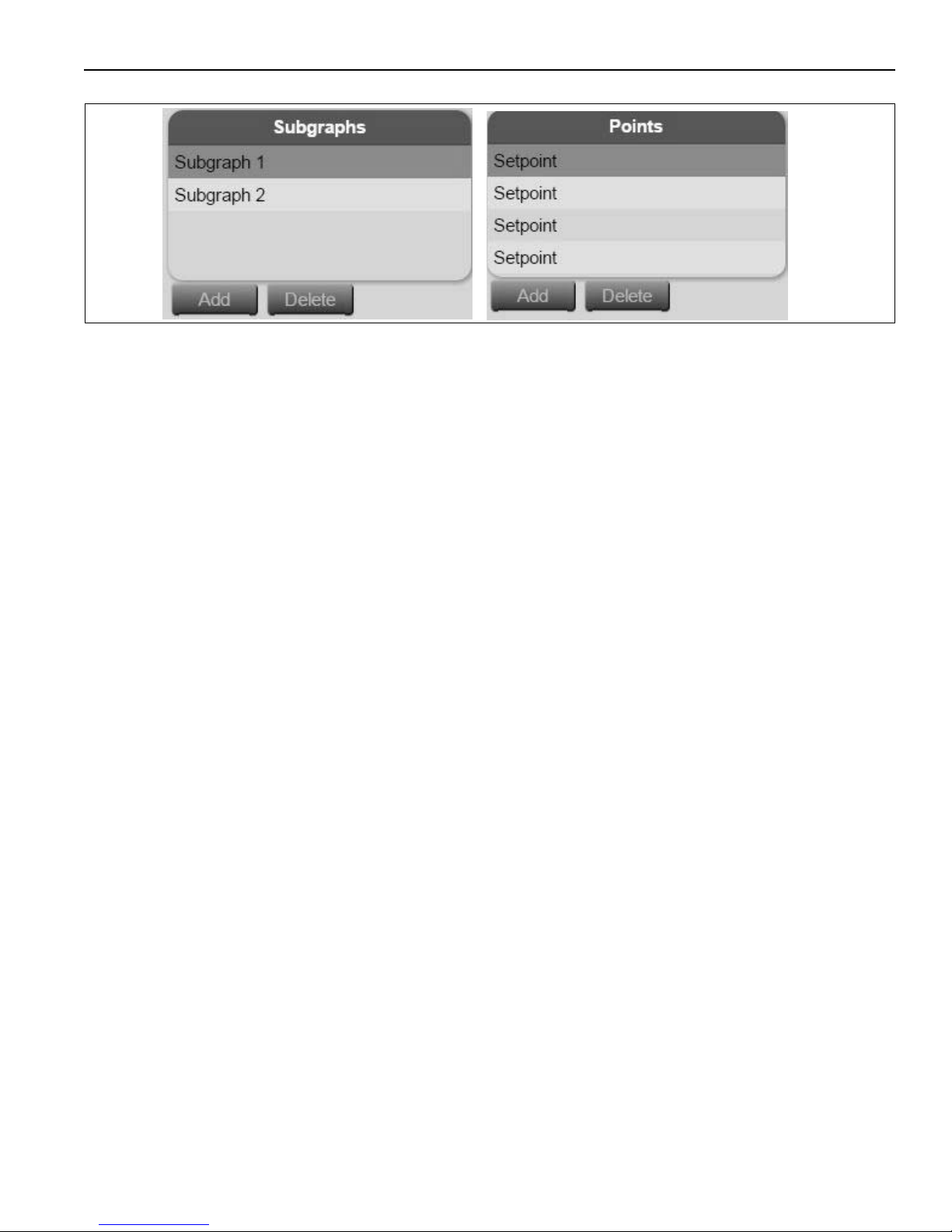
First enter a desired time range for the x-axis of the plot. This can be adjusted on-the-fly as required. Up to 16
trend points can be added to a graph. This is done using up to 4 subgraphs which can each take 4 trend
points. Use the Add and Delete buttons as necessary.
26
Page 31
SECTION 6: WEBCTRL®
For each parameter under Points, the tree beneath shows the associated object. Organize trends points and
subgraphs as desired. It is helpful to group like points on subgraphs such as: Zones 1 - 4 temperatures on
one subgraph, Zones 1 - 4 Burner on/off status on another. Click Accept at the top after changes are made.
Trend Graphs may also be deleted at any time using the Delete Trend Graph button at the top right of the
Trends Configure screen.
27
Page 32
VIRTUAL WALL™ CONTROLLER INSTALLATION MANUAL
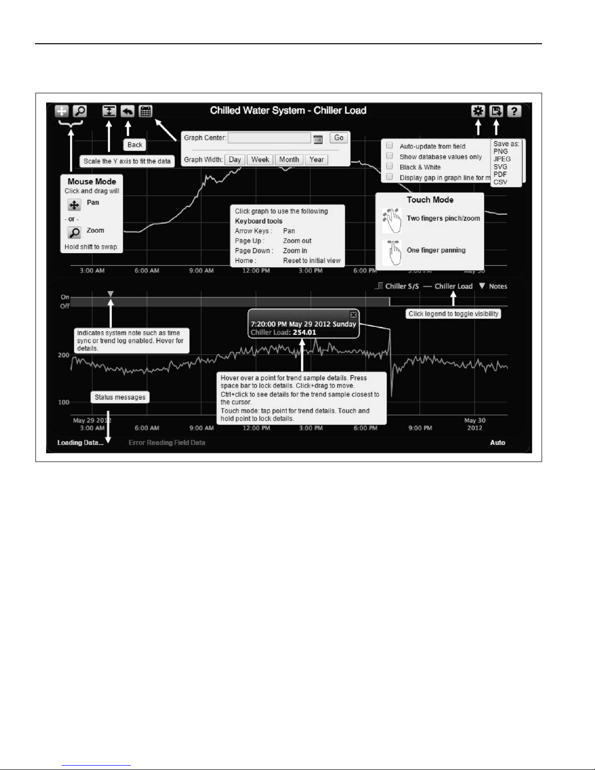
6.8.3 Monitoring Trend Graphs
Review the layout of the trend graphs and available tools below.
6.8.4 Data Storage
Once trending has been setup and running, a Trend Usage Report is a helpful tool to check and monitor
data collection. The report is a check for trend setup and not data analysis. See details in Reports section.
It is possible to calculate the trend data storage needs for the WebCTRL® database, but is easier to use the
Trend Usage Report or to check the size of the log folder within the database. From either of these options,
an approximate extrapolation can be made to determine how much space is needed.
To check log folder size:
Navigate to the local C drive and find the WebCTRL_for_OEMs_XX folder.
Then, webroot database name (i.e. Virtual Wall) databases (at the top) trend log
Right click the log folder properties. This should display the size of the folder. If it is desired to store data
for longer periods of time (i.e. 1 year) the size of this folder can be extrapolated after a w
better understand storage needs.
28
eek or month to
Page 33
SECTION 6: WEBCTRL®
6.9 Alarms
An alarm is a message sent from the controller to the WebCTRL® application to notify the user that certain
conditions exist, such as a piece of equipment has stopped running or a temperature is too low. Information
about the alarm is displayed on the Alarms button. The WebCTRL® application can also perform alarm
actions to inform personnel of the condition and record relevant information.
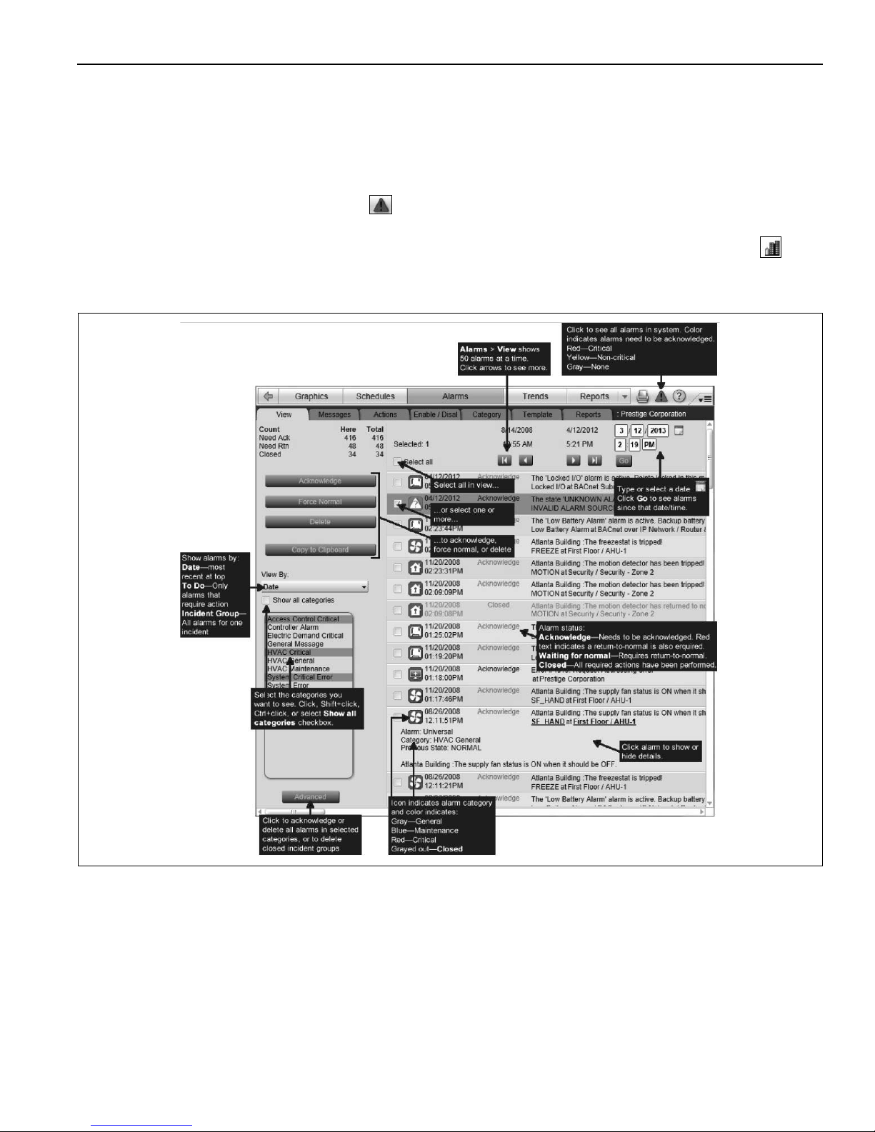
To view all alarms in the system, click the at the top right of the screen. Alternately, view alarms for
specific areas or pieces of equipment by selecting the item within the Geographic tree and then clicking the
Alarms button. Alarms generated by controllers appear at the system level in the Geographic tree . Use
the arrow buttons to scroll through alarms. Left arrow for older alarms. In addition to custom alarms, the
WebCTRL® application has built-in system and equipment alarms.
The figure below gives a detailed breakdown of the action pane in the Alarms button.
There are several ways to control w
By, and Categories as needed.
hich alarms are displayed. Use the scroll arrows, date entry field, View
29
Page 34
VIRTUAL WALL™ CONTROLLER INSTALLATION MANUAL
Acknowledge Alarms
Acknowledge alarms that have been set up to require acknowledgment. The alarm indicates when
acknowledgment is necessary. Further action after acknowledgment may be necessary to clear alarm.
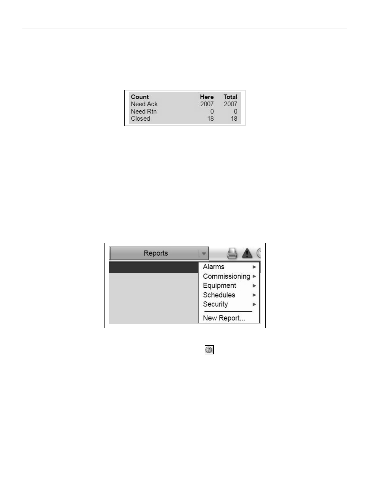
The table in the upper left corner shows how many alarms need acknowledgment at the current location
(Here) and the entire system (Total). The table also shows how many alarms need a return-to-normal and
how many are closed. You should delete alarms from your system as they are closed because large
quantities of stored alarms can reduce the efficiency of your system.
Use the Advanced button at the bottom left to perform actions to all alarms within a category at once.
Multiple categories may be selected at once.
For system efficiency, delete alarms as they are closed. To save alarm information before deleting, select the
dropdown menu on the Reports tab, then Alarms and click Run
. Save the report for records.
Alarm categories sort related alarm sources and their alarms into groups such as HVAC Critical and HVAC
General. Categories allow the user to easily view, acknowledge, or delete alarms as well as assign alarm
actions. Check the box for show all categories to view all alarms.
6.10 Reports
The Reports feature of WebCTRL® is another tool to monitor and troubleshoot your system. To run a report,
select an item in the Geographic or Network tree. Click the drop-down menu on the Reports action button
and select a report within one of the sub menus.
On the Options tab under Reports, define the layout and content of the report. Click Run.
Explore the various preconfigured reports available. For more information on a report, navigate to that report
by selecting it within the drop-do
wn menu and then click the . This will open a new internet browser tab
with additional information.
30
Page 35
SECTION 6: WEBCTRL®
6.10.1 Creating an Equipment Summary Report
This report can provide information on zone color, active alarms, locked values, current value of selected
points, and effective schedule. The report is created for equipment at or below the location selected in the
Geographic or Network trees.
Choose a tier level for report. For all equipment, choose top level system within Geographic tree. In the
Reports drop-down menu, choose New Report. Select the bullet for Equipment Summary under 'Select a
report format'. Type a name for report and Create. View and Design tabs appear. Under the Design tab,
define report format, check or uncheck any Optional Sections, and Add any Available Points desired.
Accept changes at the top when prompted and then Run the report.
Once the report has been created, it will remain an option within the drop-down menu of Reports. This
option will only appear at the Geographic level at which it was created.
Alternately, create an Equipment Values report. This report can be used to create more succinct tables of
Available Points for comparison. Create this report in a similar fashion to the Equipment Summary, but
choose Equipment Values under 'Select a report format'. Add control programs to the rows and Available
Points to the columns. There are many Available Points to choose from. The programs selected will
determine which points are available. See the list below for suggested points. Point names listed as they
appear in the dropdown menu. 'X' used in place of desired number 1 - 4.
Suggested A
vailable Points:
• Setpoint/Heating Occupied Setpoint
• Setpoint/Heating Unoccupied Setpoint
• Zone Temp
• Network OAT
• Schedule
• Pump Speed Target (i.e. the % modulation)
• Vac Pump X on/off
• Actual Speed Pump X (Hz)
• Zone X Burner S/S
• Burner X % (Unitary Modulating heaters only)
• Heat Request to Htr Prog
6.10.2 Trend Sample Report
The trend sample report can be used to gather trend data in a document format. To create this report, select
the location you want to view the report within the Geographic tree. Create a New Report and select Trend
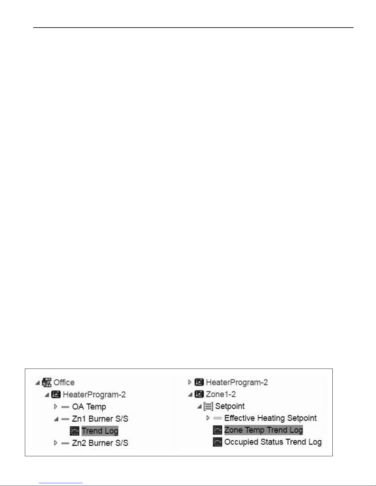
Samples. Within the report select a Time Range and desired display of information in rows. Next select col-
umn data. Add a column, fill in the heading, and select a trend source from the tree underneath. Examples of
trend sources are shown below.
31
Page 36
VIRTUAL WALL™ CONTROLLER INSTALLATION MANUAL
6.10.3 Trend Usage Report
A Trend Usage Report is a helpful tool to analyze setup and history of trending points throughout the
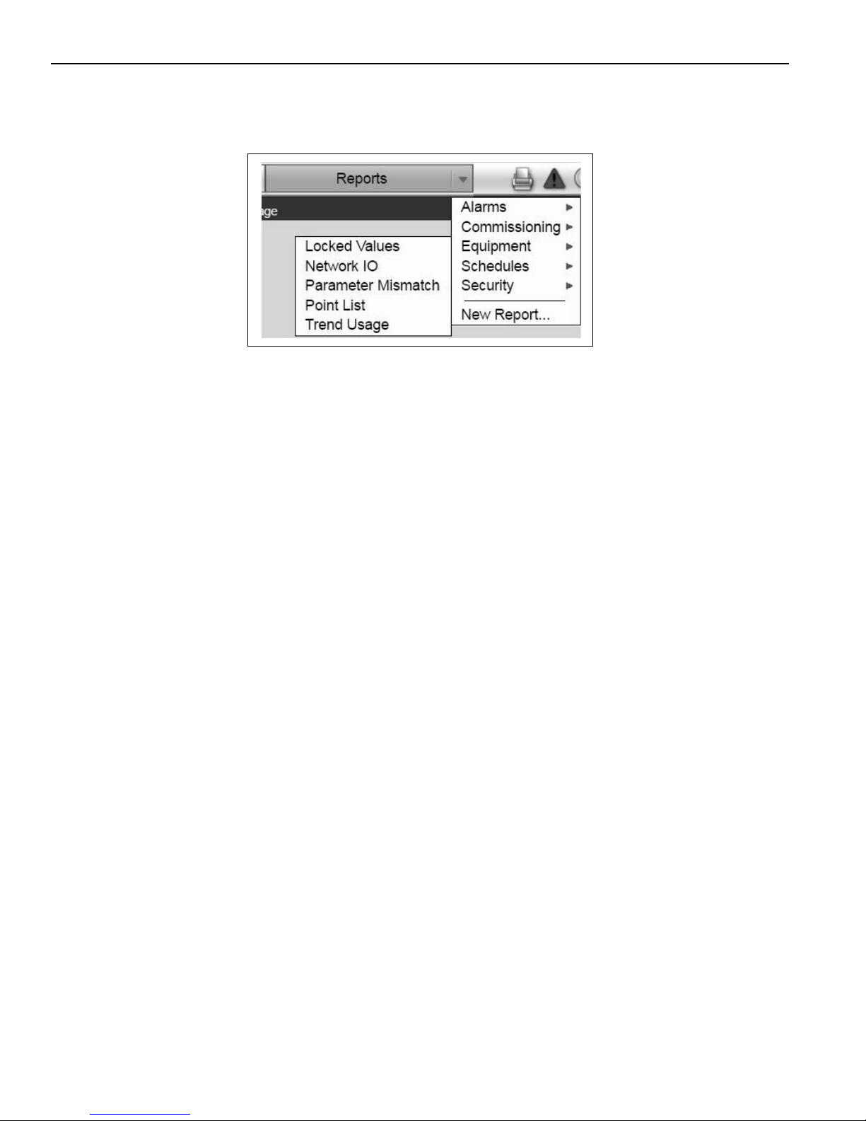
system. To run this report, first select the system, area or equipment within the Geographic tree. Within the
drop-down menu for Reports select Equipment, then Trend Usage.
Check the boxes for items to include in the report. Include 'Samples in Database' to help determine storage
requirements for the system as discussed in Section 6.8.4, Data Storage. Each trend sample consumes
approximately 30 bytes of memory. After trending has collected data consistently for some time, run the
report, add up the samples in database and extrapolate out to determine your storage needs. If no changes
were made to the factory default trend sampling setup, 2 GB of space should be sufficient for approximately
1 year of data storage.
32
Page 37

SECTION 6: WEBCTRL®
6.11 Refining the System
To maximize energy savings, the system should be refined once installed to minimize energy usage. Tips to
accomplished this will be discussed in this section.
The most important concept of the Virtual Wall is 'comfort where you need it'. This is an energy saving
technique which keeps unoccupied spaces at a lower temperature than occupied areas. This implies using
Roberts Gordon Infrared Equipment only when and where necessary. The main function of the Rapid unit is
to satisfy make up air requirements as well as building pressurization, but some supplemental heat will also
be provided by it. The Rapid unit will likely run continuously during occupied periods to meet the building
pressu
re needs. Keeping the building at a slight positive pressure helps seal the space to keep heat in.
To determine ideal setpoints within CoRayVac areas, it is best to push a low plant wide temperature and
raise it as needed. Due to the radiant heating mechanism of Roberts Gordon products, setpoints can be set
lower than in typical warm air environments. Feedback from factory workers may identify that certain areas
are acceptable at a lower temperature, while others need to be increased for comfort. Use tools such as the
plant wide temperature map, and trending to monitor areas and identify the most active heating zones.
For Roberts Gordon equipment, adjustments to the External Design Temperature will determine how the
systems modulate. See the ROBERTS GORDON
®
Installation and Operation Manual (P/N 127102NA).
Do not include preheating time in occupied scheduling. The optimum start feature ensures an area is
warming up to temperature before the occupied time is reached.
33
Page 38
VIRTUAL WALL™ CONTROLLER INSTALLATION MANUAL
SECTION 7: REPLACEMENT PARTS
DANGER
Electrical Shock Hazard
Use only genuine ROBERTS GORDON® replacement parts per this installation, operation and
service manual.
Failure to follow these instructions can result in death, electric shock, injury or property damage.
See warnings and important information before removing or replacing parts. After any maintenance or repair
work, always test fire the heater in accordance with the start-up instructions per the heaters current Installa-
tion, Operation and Service manual to help ensure all safety systems are in working order before leaving the
heater to operate. Minor faults may be traced by using the troubleshooting charts.
Explosion Hazard
WARNING
Fire Hazard
Carbon Monoxide Hazard
34
Page 39
7.1 VIRTUAL WALL™ Controller Controller Replacement Parts
Caution: Use only genuine SPECIFIED AIR SOLUTIONS
™
replacement parts. Use of parts not specified by
Roberts-Gordon voids warranty.
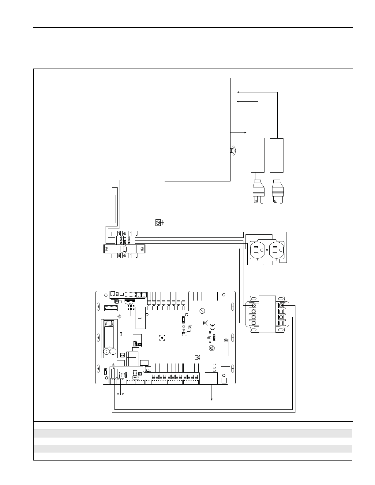
FIGURE 9: VIRTUAL WALL™ Controller Controller Components
TOUCHSCREEN & COMPUTER
1Ø 20A
L N GND
BLK WHT GRN
POWER IN
120V 60HZ
POWER IN
BOARD
ETHERNET
CONNECTION
TO CONTROL
NETWORK
TO LOCAL
WIFI CONNECTION
OUTPUT: 12VDC 4.0A
TOUCHSCREEN ADAPTER
SECTION 7: REPLACEMENT PARTS
COMPUTER ADAPTER
OUTPUT: 12VDC 5.0A
Port 1 Rx
Port 1 Tx
2A, 50-60 Hz
24Vac, 50VA
Without Keypad:
Power
24Vac
26Vdc
26Vdc, 23W, 0.9A
Gnd
External
Conductors
ONLY Use Copper
Off On
G
N
N
CB
20A
3
2
1
65478
6
31245
7
8
Off
1's
5
4
3
2
1
1
2
AssignedDefault
IP Addr
BAS Port
Enhanced
See BAS Table Below
3 = Comm setup error
1 = Control Program Error
4 = System error
8 = Formatting
2 = RAM full
EIA-232
Port 2a
Gnd
Rnet+
Port 2a
Tx
Rx
DTR
EIA-232
Tx -
Tx +
Rx +n/c
Net-
Net+
2 wire4 wire
CONTROLLERS
Off
On
Access Port 2a
BAS Port Settings
EIA-485
Rnet-
+12V
DCD
Rx -
Signal Ground
n/c
10's
Address
Controller
8
On
On
On
Off
Off
Off
Off
7
On
OffOnOff
Off
On
Off
6
Off
On
Off
Off
On
UO-8
UO-7
N2 On
PTP Off
Modbus
MS/TP s
MS/TP m
Protocols
Lon SLTA
Lon Option
BACnet
5
4
9600 Off Off
19.2 K Off On
38.4 K On Off
76.8 K On On
BAUD
2-wire
4-wire
I/O Pro 812u
Sense
Local
Access
Rnet
+12V
Rnet -
Gnd
Rnet +
Xnet Expansion
UI-1
Gnd+Gnd
Xnet +
Xnet -
Gnd
1
CONTROLLER
UI-2
+
UO-3
UO-4
UO-6
UO-5
®
UI-4
UI-3
UI-6
UI-7
UI-5
+
+
+
+
Gnd
Gnd
Gnd
1
8765432
+3V
Gnd
876
Format
Battery
Int. Batt.
Ext. Batt.
Brownout
Port 2a Tx
Port 2a Rx
Battery low
Archive Valid
Status
0 = Download required
Chase = OK
Status Codes
Blinking Dot = 'Run'
Module
CR-123A
3V Lithium Battery
Port 1
Port 2a BT485
Port 1 BT485
485
156
ARC-
Power
Class 2
Port 1
Shield
Net -
Net +
TO ADDITIONAL
UO-7
UO-6
UO-8
UO-2
UO-1
Auto Off On
Set Pot Full CW
Pot
Relay
0-10Vdc
0-20mA
Mode Select
Universal Input
Volts
Thermistor/
dry-contact/
mA
10V Max, 20mA Max
Inputs: All
UI-12
UI-11
UI-10
UI-8
UI-9
+
+
+
Gnd+Gnd
Gnd+Gnd
Gnd
Gnd+Gnd
8765432
8765432
1
ETHERNET
UO-5
24Vac
DO NOT APPLY 24Vac TO
Open Energy
Management Equipment
RTD
TOUCHSCREEN
CONNECTION TO
UO-4
UO-3
Outputs
24Vdc Max, 50mA Max
UNIVERSAL OUTPUTS
External 24Vdc relay coil only
10/100 BaseT
Ethernet Port E1
Rev 6
07/10/12
IOPro812u
(RJ45)
Gnd+Gnd+Gnd+Gnd+Gnd+Gnd+Gnd+Gnd
UO-2
88F0
E143900
100 LAN LINK
+
UO-1
®
Made in USA
BACnet
Over ARCNET156 KBaud
TYPE: 002003
Port 2b
24 Vdc
24 Vdc
Aux Power Out
200mA maximum
L
L
G
N
G
N
H4
H2
H3
H1
24Vac
N1/Gnd
TRANSFORMER
Description
Control Board 10061001
Transformer 24vac to 120vac 10061009
120V Control Power Circuit Breaker 10061007
15" Wide Screen Touchscreen 10061017
Part Number
35
Page 40

VIRTUAL WALL™ CONTROLLER INSTALLATION MANUAL
SECTION 8: THE VIRTUAL WALL
™
CONTROLLER LIMITED WARRANTY
Within 36 months from date of purchase by buyer or 42
months from date of shipment by Specified Air Solutions
(whichever occurs first), replacement parts will be provided
free of charge for any part of the product which fails due to
a manufacturing or material defect.
Specified Air Solutions will require the part in question to
be returned to the factory. Specified Air Solutions will, at its
sole discretion, repair or replace after determining the
nature of the defect and disposition of part in question.
SPECIFIED AIR SOLUTIONS
™
Replacement Parts are
warranted for a period of 12 months from date of shipment
from Specified Air Solutions or the remaining VIRTUAL
™
WALL
Controller warranty.
SPECIFIED AIR SOLUTIONS WILL NOT PAY FOR:
Service trips, service calls and labor charges.
Shipment of replacement parts.
Claims where the total price of the goods have not
been paid.
Damage due to:
• Improper installation, operation or maintenance.
• Misuse, abuse, neglect, or modification of the
VIRTUAL WALL
• Use of the VIRTUAL WALL
™
Controller in any way.
™
Controller for other than
its intended purpose.
• Incorrect gas or electrical supply, accident, fire, floods,
acts of God, war, terrorism, or other casualty.
• Improper service, use of replacement parts or accessories not specified by Specified Air Solutions.
• Failure to install or maintain the VIRTUAL WALL
™
Controller as directed in the Installation, Operation and
Service Manual.
• Relocation of the VIRTUAL WALL
™
Controller after ini-
tial installation
• The use of the VIRTUAL WALL
™
Controller in a corro-
sive atmosphere containing contaminants.
• The use of the VIRTUAL WALL
™
Controller in the vicin-
ity of a combustible or explosive material.
• Any defect in the VIRTUAL WALL
™
Controller arising
from a drawing, design, or specification supplied by or
on behalf of the consumer.
• Damage incurred during shipment. Claim must be filed
with carrier.
WARRANTY IS VOID IF:
The VIRTUAL WALL™ Controller is not installed by an
electrician qualified in the installation and service of
control systems for heating equipment.
Yo u cannot prove original purchase date and required
annual maintenance history.
The data plate and/or serial number are removed,
defaced, modified or altered in any way.
The ownership of the VIRTUAL WALL
moved or transferred. This warranty is nontransferable.
Specified Air Solutions is not permitted to inspect the
damaged controller and/or component parts.
™
Controller is
READ YOUR INSTALLATION, OPERATION AND
SERVICE MANUAL.
If you have questions about your control, contact your
installing professional. Should you need Replacement
Parts or have additional questions, call or write:
Specified Air Solutions
1250 William Street
P. O . B o x 4 4
Buffalo, New York 14240-0044
Telephone: +1.716.852.4400
Fax: +1.716.852.0854
Toll Free: 800.828.7450
www.specifiedair.com
Specified Air Solutions's liability, and your exclusive
remedy, under this warranty or any implied warranty
(including the implied warranties of merchantability
and fitness for a particular purpose) is limited to
providing replacement parts during the term of this
warranty. Some jurisdictions do not allow limitations on
how long an implied warranty lasts, so this limitation may
not apply to you. There are no rights, warranties or
conditions, expressed or implied, statutory or otherwise,
other than those contained in this warranty.
Specified Air Solutions shall in no event be
responsible for incidental or consequential damages
or incur liability for damages in excess of the amount
paid by you for the VIRTUAL WALL
™
Controller. Some
jurisdictions do not allow the exclusion or limitation of
incidental or consequential damages, so this limitation or
exclusion may not apply to you. This warranty gives you
specific legal rights, and you may also have other rights
which vary from jurisdiction to jurisdiction.
Specified Air Solutions shall not be responsible for failure
to perform under the terms of this warranty if caused by
circumstances out of its control, including but not limited to
war, fire, flood, strike, government or court orders, acts of
God, terrorism, unavailability of supplies, parts or power.
No person is authorized to assume for Specified Air
Solutions any other warranty, obligation or liability.
LIMITATIONS ON AUTHORITY OF
REPRESENTATIVES:
No representative of Specified Air Solutions, other than an
Executive Officer, has authority to change or extend these
provisions. Changes or extensions shall be binding only if
confirmed in writing by Specified Air Solutions's duly
authorized Executive Officer.
36
 Loading...