

Special Tomato Large Hi-Low MPS Service Manual
Service Manual
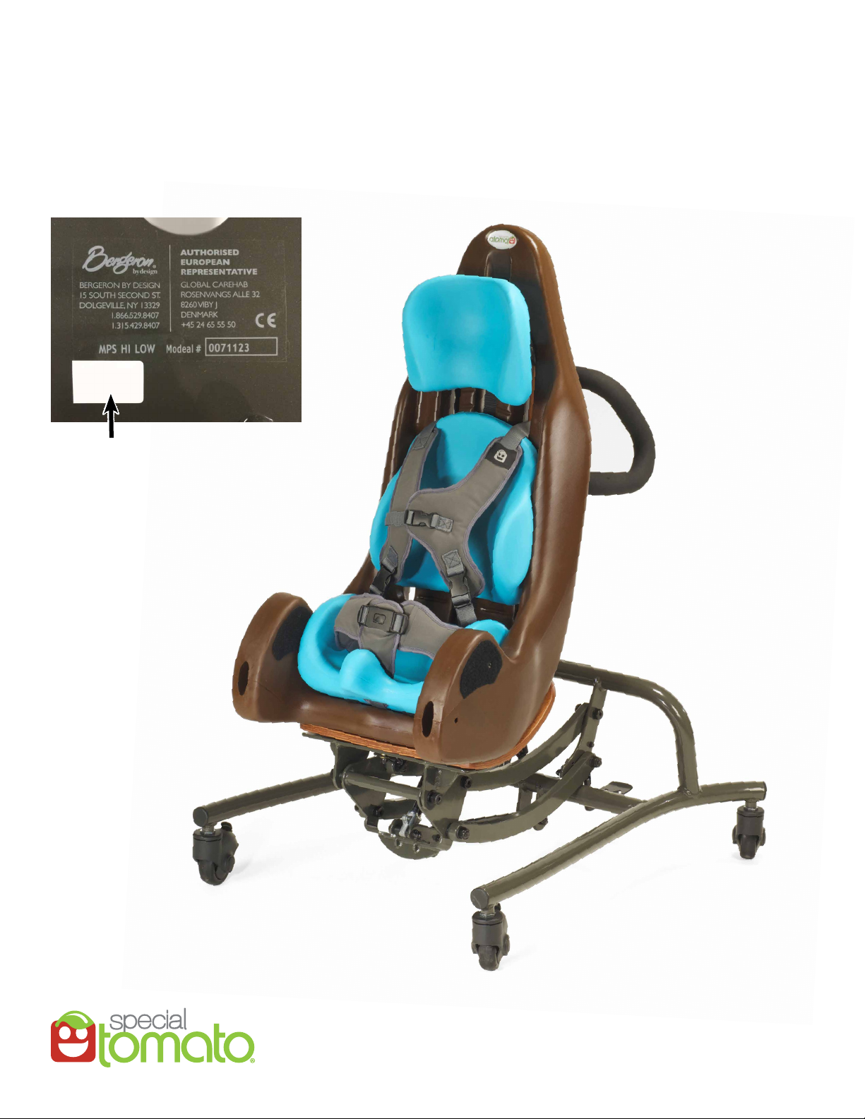
Large Hi-Low MPS
Date Code: 01/16
(Location under seat pan)
01/16
Date Code
SMHLM(C5)01-16LIT

Table of Contents
1. MPS to Base Interface Bolt Replacement . . . . . . . . . . . . . . . . . . . . . . . . . . . . . . . . . . . . . . . . . . . 1
2. 4-Bar Bolt Replacement . . . . . . . . . . . . . . . . . . . . . . . . . . . . . . . . . . . . . . . . . . . . . . . . . . . . 3
3. Assist Piston Replacement . . . . . . . . . . . . . . . . . . . . . . . . . . . . . . . . . . . . . . . . . . . . . . . 4
4. Tilt Piston Replacement and Calibration . . . . . . . . . . . . . . . . . . . . . . . . . . . . . . . . . . . . . . 6
5. Tilt Lever Assembly Replacement and Calibration . . . . . . . . . . . . . . . . . . . . . . . . . . . . . . 8
6. Lift Piston Replacement and Calibration . . . . . . . . . . . . . . . . . . . . . . . . . . . . . . . . . . . 9
7. Foot Pedal Assembly Replacement and Calibration . . . . . . . . . . . . . . . . . . . . . . . . . . . 11
8. Caster Replacement . . . . . . . . . . . . . . . . . . . . . . . . . . . . . . . . . . . . . . . . . . . . . . . . . . . . . . 12
9. Tube Cap Replacement . . . . . . . . . . . . . . . . . . . . . . . . . . . . . . . . . . . . . . . . . . . . . . . . . . 13
10. Strapping – Upper Strap Replacement (Shoulder/Midsection) . . . . . . . . . . . . . . . . . . . . . . . . . 13
11. Strapping – Lower Strap Replacement (Pelvic/Crotch) . . . . . . . . . . . . . . . . . . . . . . . . . . . . . . . . 15
12. Removable Handle . . . . . . . . . . . . . . . . . . . . . . . . . . . . . . . . . . . . . . . . . . . . . . . . . . . . . . . . . . . . 16
13. Assist Piston Lift Kit (Sold Separately) . . . . . . . . . . . . . . . . . . . . . . . . . . . . . . . . . . . . . . . . . . . . . . . . 16
Tools Required
4mm Allen Wrench
6mm Allen Wrench
10mm Crescent Wrench
13mm Crescent Wrench
14mm Crescent Wrench
18mm Crescent Wrench
21mm Thin Crescent Wrench
Pry Tool
1. MPS Base to Base Interface Bolt Replacement
A. Remove MPS Tray, Foot Rest Assembly, and Arm Rests.
B. Lower seat to oor by engaging pedal. (Weight in the seat may be needed to assist with lowering)
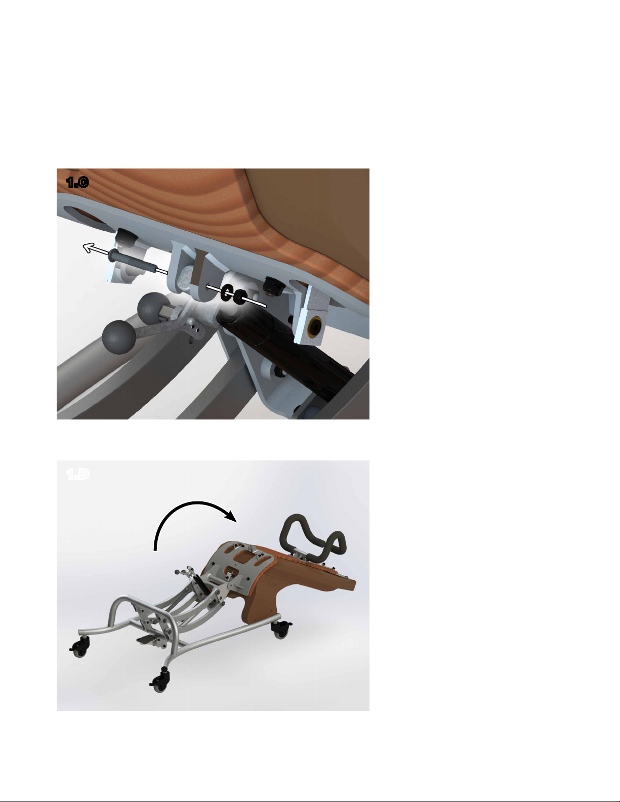
C. Remove tilt release-head bolt. (Requires: 4mm Allen, 10mm Crescent Wrench)
1.C
D. Rotate seat forward until seat touches oor.
1.D
1
1. MPS Base to Base Interface Bolt Replacement (cont.)
E. Raise the seat slightly so seat sits naturally at three points (Head Support and Armrest Supports)
with all 4 wheels on the ground. This will assist with reassembly. (Tapping pedal once should level
the seat)
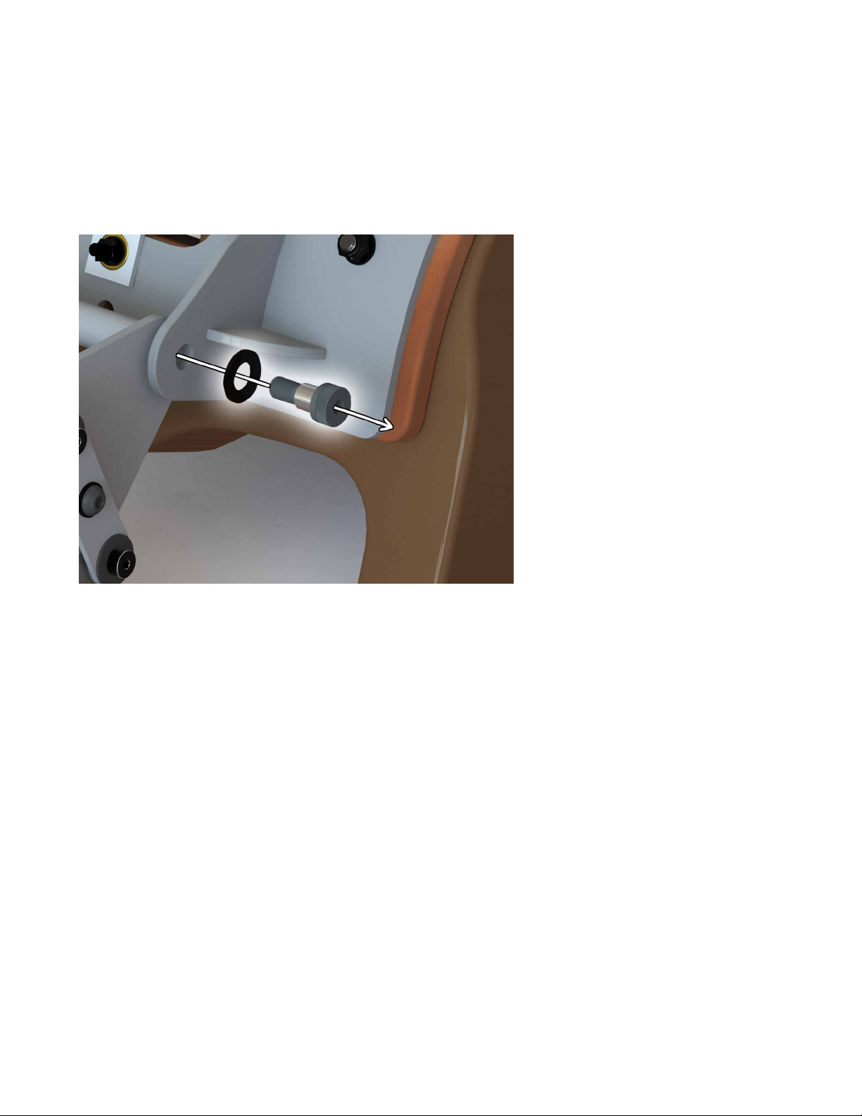
F. Unscrew Interface Bolt (Requires: 6mm Allen Wrench)
1.F
G. Replace Interface Bolt with Provided Replacement Bolt Assembly. (Requires: 6mm Allen Wrench.)
* Steps A through F (removing right and left interface bolts which removes the seat from base) are
necessary to complete other repair and calibration procedures.
2
2. 4-Bar Bolt Replacement
A. Remove the entire seat from base. (Refer to Procedure 1)
B. Remove desired 4-Bar Bolt. (Requires: 4mm Allen, 10mm Crescent Wrench)
C. Replace with provided Bolt Assembly Hardware. (Requires: 4mm Allen, 10mm Crescent Wrench)
* Steps A through C (removing desired 4-Bar Bolt) are necessary to complete other repair and
calibration procedures.
!
CAUTION: 4-Bars with Assist Pistons are under tension.
3
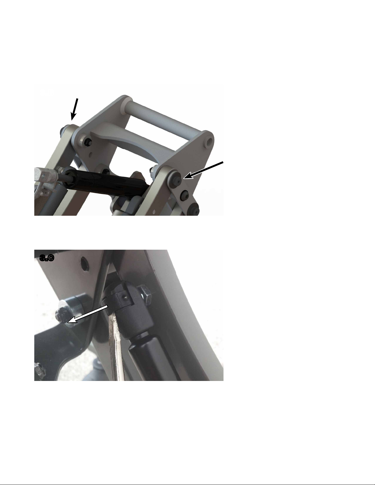
3. Assist Piston Replacement
A. Remove the entire seat from base. (Refer to Procedure 1)
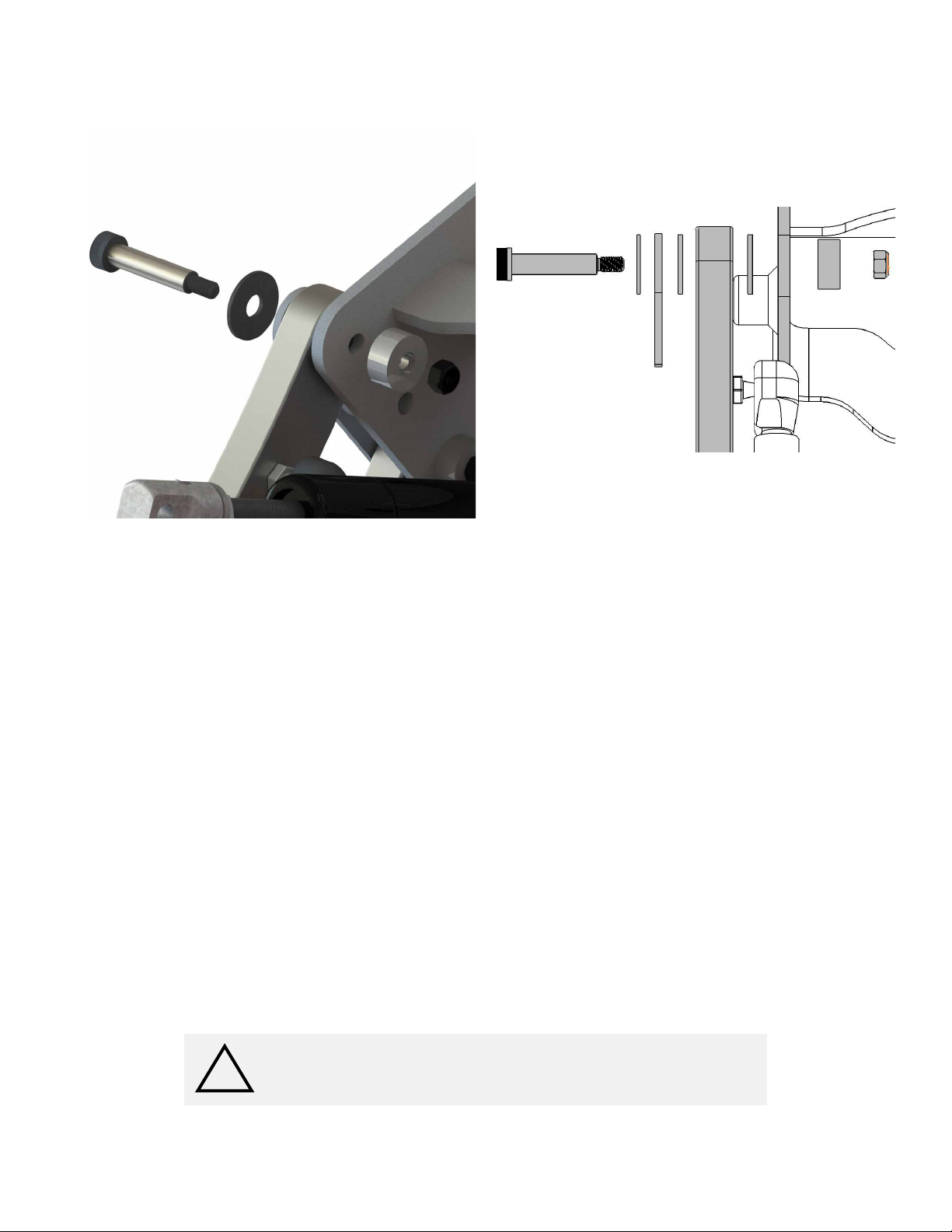
B. Remove desired 4-Bar Bolt. (Refer to Procedure 2)
3.B
C. Use pry tool to release one piston head from ball joint by slightly lifting the retaining band as
show below (do not completely remove retaining band). (Requires: Pry Tool)
3.C
D. Repeat step C on the other release-head to remove piston. (Requires: Pry Tool)
E. Attach new piston at lower ball joint by snapping head onto ball (piston head down). (No tool
required)
4
 Loading...