

Special Stage Systems MING MECCA User Manual
i

ii
ABOUT SPECIAL STAGE SYSTEMS
Special Stage Systems was founded by Jordan Bartee in 2011. The company
operates out of Special Stage Laboratories in Seattle, WA.
Special Stage Systems is:
—Jordan Bartee: Design, engineering, firmware development
—Chris Novello: Design
—Molly Roberts: Software development
FIRST EDITION
FIRST PRINTING—2014
© 2014 Special Stage Systems

iii
MING MECCA
USER’S GUIDE

iv
TECHNICAL SPECIFICATIONS
SPEC
CONTROL CORE
WORLD CORE
HP width
14HP (2.8”)
56HP (11.2”)
Depth
1.75”
1.98”
Current consumption
5V INT
+12V: 210mA
+5V: 0mA
-12V: 0mA
5V EXT
+12V: 145mA
+5V: 65mA
-12V: 0mA
5V INT
+12V: 250mA
+5V: 0mA
-12V: 0mA
5V EXT
+12V: 165mA
+5V: 85mA
-12V: 0mA
CV input range
0-5V
0-5V / 0-1V selectable
CV output range
0-10V
N/A
Gate input threshold
+2.2V
+0.5V
Gate output level
+10V
+10V
Peripheral
compatibility
NES gamepads
—Original
—“Dogbone”
—Advantage
Displays
NTSC
Composite video
SD CARDs
Full size
FAT16 / FAT32 format

v
TABLE OF CONTENTS
INTRODUCTION ......................................................... vii!
1. SETUP ............................................................................1
Unpacking and Inspecting your Module ...................................3
Selecting and Calibrating the CV Range ..................................4
Linking a Control Core ...........................................................8
Configuring and Connecting Power .......................................11
Connecting a Display ...........................................................17
Powering on the World Core for the First Time .......................19
2. BASIC OPERATION ............................................21
System Overview and Interface Guide ...................................23
Voltage Standards and General Control Paradigms ...............26
How to Read Patch Schematics ..............................................29
Returning to Default Settings .................................................35
3. TILES .............................................................................37
Overview .............................................................................39
Data Structure ......................................................................40
Building Simple Environments ...............................................43
Maps ...................................................................................46
Glitch Modes .......................................................................47
Dynamic Map Destruction (DMD) ..........................................49
4. SPRITES ......................................................................53
Overview .............................................................................55
Data Structure ......................................................................56
Clipping ..............................................................................59
Collision ..............................................................................63
Sprite 1: Directional Inputs ....................................................65
Sprite 1: Gravity ...................................................................67

vi
5. WORLD PACKS .................................................... 75
Using the Cartridge Slot ....................................................... 77
Creating and Modifying WPACK.TXT Files ............................. 80
Creating and Modifying CONFIG.TXT Files ........................... 85
Generating WPACK.TXT Files with WPACKer ......................... 88
Building Better Worlds .......................................................... 91
APPENDICIES .............................................................. 95!
A: ADVANCED TECHNIQUES .............................................. 95
Walk Cycles ........................................................................ 97
Sprite Multiplexing and ASFM ............................................... 98
Multi-Map Composition ..................................................... 102
B: CONTROL CORE MANUAL ............................................ 107
Introduction ....................................................................... 109
Unpacking and Inspecting your Module .............................. 110
Linking a World Core ......................................................... 111
Configuring and Connecting Power .................................... 111
System Overview and Interface Guide ................................. 116
Voltage Standards and General Control Paradigms ............. 117
Gamepad Operation ......................................................... 119
Turbo Modes ..................................................................... 121
Unleashing the Chaotix Oscillator ...................................... 122
C: TROUBLESHOOTING CHART ........................................ 125!
INDEX ............................................................................. 129
!

vii
INTRODUCTION

viii

ix
Thank you for purchasing a Special Stage Systems WORLD CORE,
the central module in the MING MECCA voltage controlled videogame console. The WORLD CORE is a video-generating EURORACK
module that uses TILEs, SPRITEs, and COLLISIONs to create video-
game-like graphical environments. We like to think of it as an “ontological toy”—a philosophical laboratory for creating, exploring, and
experimenting with interactive virtual worlds. But the WORLD CORE
can be used for all sorts of different purposes. In addition to its
world-building capabilities, it’s also extremely powerful as a deep
and fully customizable digital video synthesizer, as well as a unique
voltage controlled GATE and TRIGGER generator.
Although the WORLD CORE is fully functional as a stand-alone unit,
it can also be connected to one or more CONTROL COREs to form an
enhanced MING MECCA system. The CONTROL CORE interfaces with
NES-compatible gamepads and converts their output into modular-
friendly voltages. For users who are interested in experimenting with
videogame mechanics and world exploration, we highly recommend
the purchase of at least one CONTROL CORE for moving SPRITEs and
manipulating world-states. The full CONTROL CORE manual is included in APPENDIX B; if you own or plan to own a CONTROL CORE, we
recommended that you read this first, since some of the WORLD
CORE patch examples assume familiarity with it.
MING MECCA has been designed as an extendable platform, with
many more CORE modules planned for eventual release. If you
would like to be notified as new designs are announced, please consider signing up for the Special Stage Newsletter via our contact
page at specialstagesystems.com/contact.
Finally, all of us at Special Stage Systems would like to thank you
for joining us on this new adventure. We can’t wait to see what
strange and exciting worlds you discover.


1
1. SETUP
• Unpacking and Inspecting Your Module
• Selecting and Calibrating the CV Range
• Linking a CONTROL CORE
• Configuring and Connecting Power
• Connecting a Display
• Powering on the WORLD CORE for the First Time

2

3
UNPACKING AND INSPECTING
YOUR MODULE
In addition to the USER’S GUIDE, your package should include the
following items:
1. WORLD CORE module
2. 16-to-16 pin ribbon POWER CABLE (attached to the back of
the module)
3. 16-to-10 pin ribbon LINK CABLE (unattached)
If any of these items are missing, please contact Special Stage
Systems to request a replacement.
Before setting up your WORLD CORE, it’s important to perform a
quick visual inspection to make sure the module has not been damaged during shipping. First check the FRONT PANEL and then turn the
module around to look at the MOTHERBOARD. When inspecting the
MOTHEBOARD, take care to avoid directly touching any exposed
components and connections, as this could result in electrostatic
damage. Look closely at the board and verify that none of the header pins* are bent and that there is no obvious structural damage.
If you think your WORLD CORE has been damaged or is otherwise
defective, do not attempt to install the module. Please get in touch
with Special Stage Systems at support@specialstagesystems.com to
open a support ticket.
*Headers are small rows of gold pins that are used to connect ribbon cables to the
motherboard.
4
SELECTING AND CALIBRATING
THE CV RANGE
Before you can install your WORLD CORE, you’ll need to configure
some basic settings. First we’ll look at the control voltage or “CV”
range—the span of voltage that the WORLD CORE’s analog input
jacks respond to. The WORLD CORE is configured at the factory to
respond to a 0-5V CV range. It can also be set up to use an optional
0-1V CV range, which is the standard range used by the LZX VISIONARY SYSTEM, a suite of EURORACK video modules designed and
manufactured by LZX Industries.
If you do not own an LZX VISIONARY SYSTEM, you may skip to the
next section, LINKING A CONTROL CORE; the standard factory setting
of 0-5V is the most compatible range for cross-patching with other
EURORACK modules, and does not require any user calibration.
SELECTING THE LZX-COMPATIBLE 0-1V CV RANGE
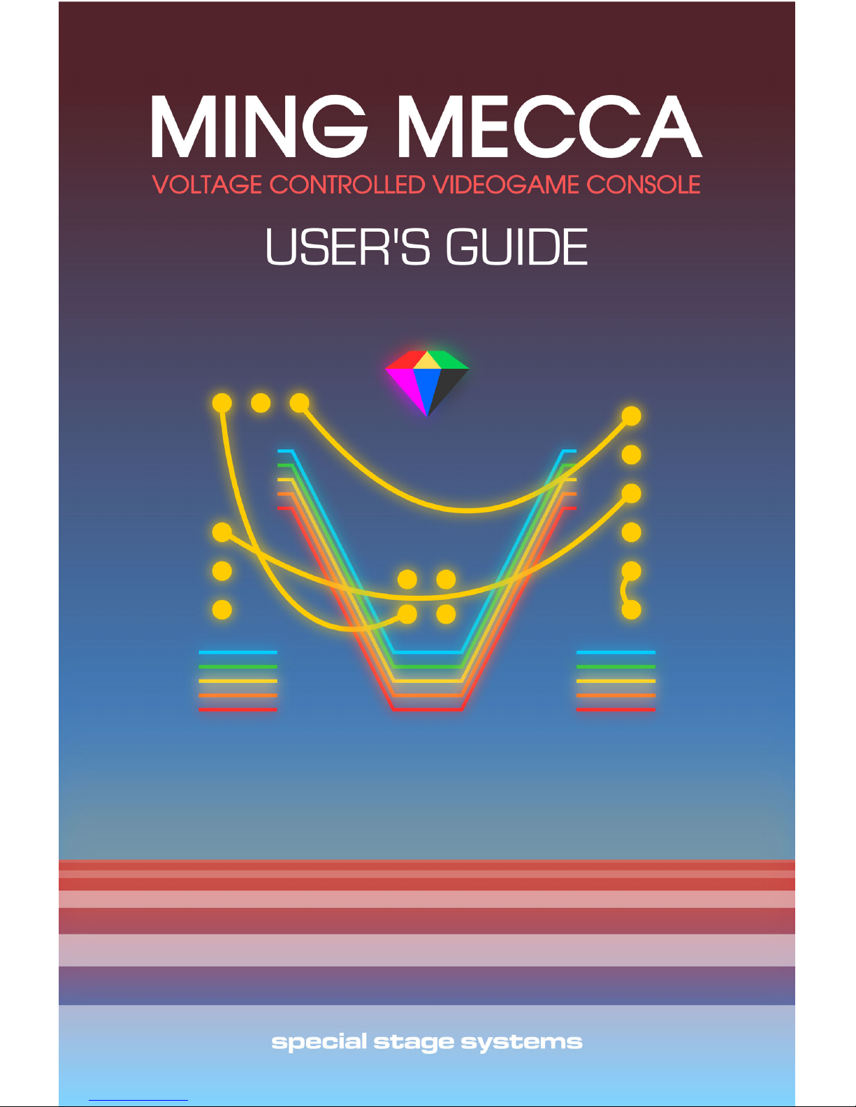
To select the LZX-compatible 0-1V CV range, first locate the CV
RANGE JUMPER on the MOTHERBOARD.
5
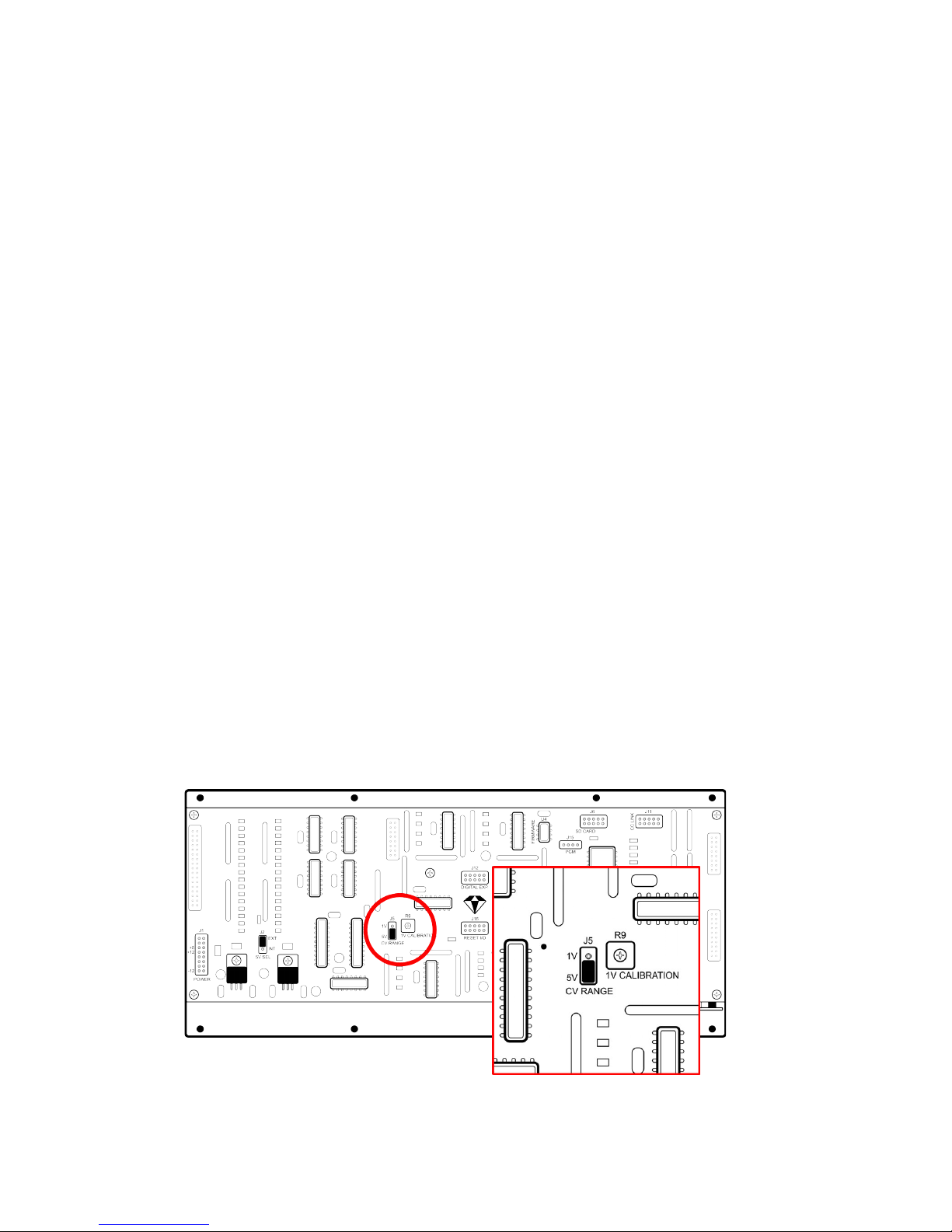
Remove the jumper and reinstall it in the 1V position, as shown in
the diagram below.
The WORLD CORE will now use a 1V reference for its CV range.
Digital GATE and TRIGGER inputs conform to a 0.5V logic threshold by
default and require no user configuration for LZX compatibility.
If you’re setting up your WORLD CORE for the first time you can
now move on to the next section, LINKING A CONTROL CORE. The
calibration instructions below are only necessary if you encounter
problems after fully installing your WORLD CORE.
CALIBRATION
The 1V reference is set by a trimpot labeled
1V CALIBRATION, located to the right of the CV
RANGE JUMPER. This trimpot is hand-calibrated
by Special Stage Systems prior to shipment
and usually requires no further adjustment.
Occasionally, the 1V reference can drift
slightly during transport. This is usually due to
mechanical vibration affecting the 1V CALIBRATION trimpot. If you
ever find that the WORLD CORE is not responding to the full 1V
range, the trimpot may need to be recalibrated. Special Stage Sys-
tems can perform this recalibration for you, or you can perform it
yourself using the following instructions.
6
WARNING: This procedure requires that the WORLD CORE be
powered on while it is removed from the case. Recalibration
is therefore recommended for advanced users only. If you
are not comfortable handling live circuitry, please contact
Special Stage Systems to arrange a factory recalibration.
To calibrate the 1V reference you will need the following items:
1. A small Phillips-head screwdriver for adjusting the trimpot
2. A voltage source capable of generating a 1V DC offset
3. A digital multimeter with a 3-4 significant digit display
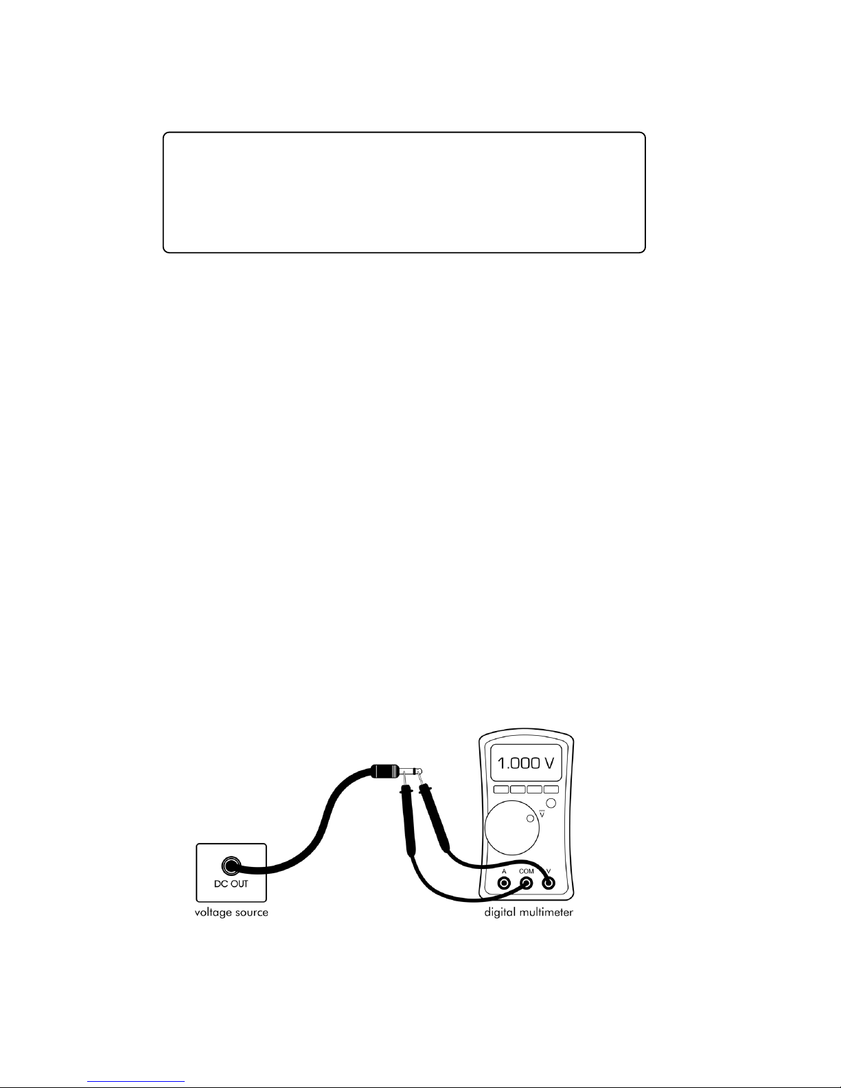
STEP 1 — S etting the voltage source
In order to calibrate the 1V reference we need to have an accurate
1V source to compare it to. Using your digital multimeter, set your
voltage source to exactly 1.000V. This is most commonly achieved by
inserting a patch cord into the voltage source’s output jack, leaving
the other side of the cord unpatched. You can then measure the voltage source by placing your multimeter’s probes across the tip and
sleeve of the patch cord.
7
STEP 2 – Removing and setting up the WORLD CORE
First make sure that you have dissipated any electrostatic charge
you may be carrying by touching a grounded metal object. Touching
a kitchen or bathroom faucet works well.
Turn off your modular synthesizer’s power and remove the WORLD
CORE from your case. Leave the power and video cables connected.
Carefully hold or set the WORLD CORE on a stable surface, make
sure your display is turned on, and then turn on your modular.
Verify that the WORLD CORE boots without issue. If you see
no video or the module is behaving erratically, immediately
turn off the power and make sure nothing is shorting out on
the MOTHERBOARD.
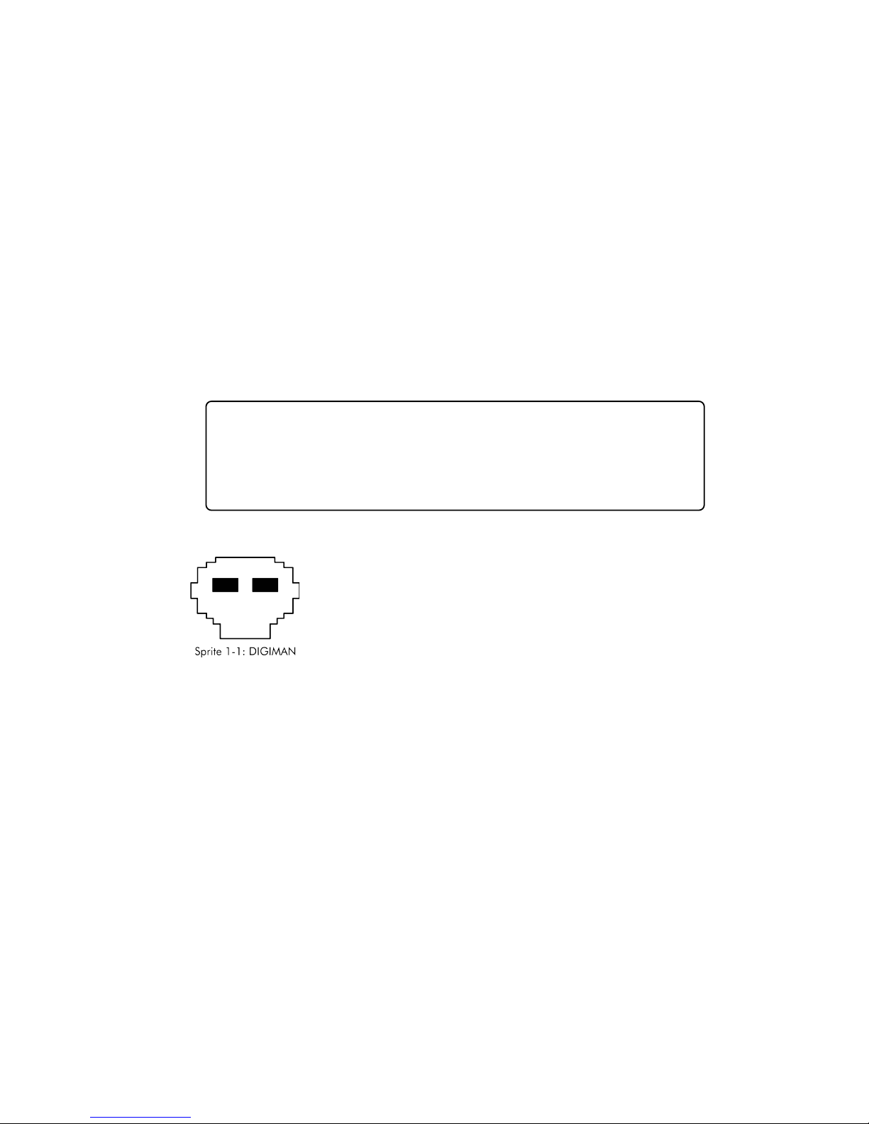
Using the X and Y knobs, position SPRITE 1 on the
center of the screen. Once SPRITE 1 is centered, turn
the OBJECT and ORIENT knobs fully counter clockwise to select the DIGIMAN SPRITE in its default state.
Now turn the Y knob fully clockwise and patch your
1V voltage source into the Y CV input. DIGIMAN should now be hid-
den (or, depending on the level of miscalibration, partially hidden)
behind the top border of the screen.
STEP 3 – adjusting the trimpot
Using your Phillips-head screwdriver, turn the trimpot counterclockwise until SPRITE 1 reappears on the screen. Now slowly turn the
trimpot clockwise until the very bottom of SPRITE 1 has just barely disappeared behind the top border. If the bottom of SPRITE 1 is flickering
in and out of the border, keep turning the trimpot until it stabilizes.
The idea is to apply just enough voltage to position SPRITE 1 fully be-

8
hind the top border. This may take several small adjustments to get
perfect.
STEP 4 – verifying the calibration
Once you’ve finished adjusting the trimpot, unpatch your voltage
source from the Y CV input. Using the Y knob, sweep SPRITE 1 from
the bottom to the top of the screen and make sure that it covers the
complete range of positions. If SPRITE 1 doesn’t completely disappear
behind the top border, patch your voltage source back into the Y CV
input and repeat STEP 3.
You have now successfully calibrated the 1V reference. You may
turn off the power and reinstall the module in your case.
Extremely advanced users may prefer to calibrate by directly
measuring the voltage across the 1V-pin on the CV RANGE
JUMPER. Ground can be tapped from the large ground-
plane connected “via” hole directly above the trimpot. Do
not attempt this method if you have no experience with
electronics—it is easy to slip and cause short circuits.
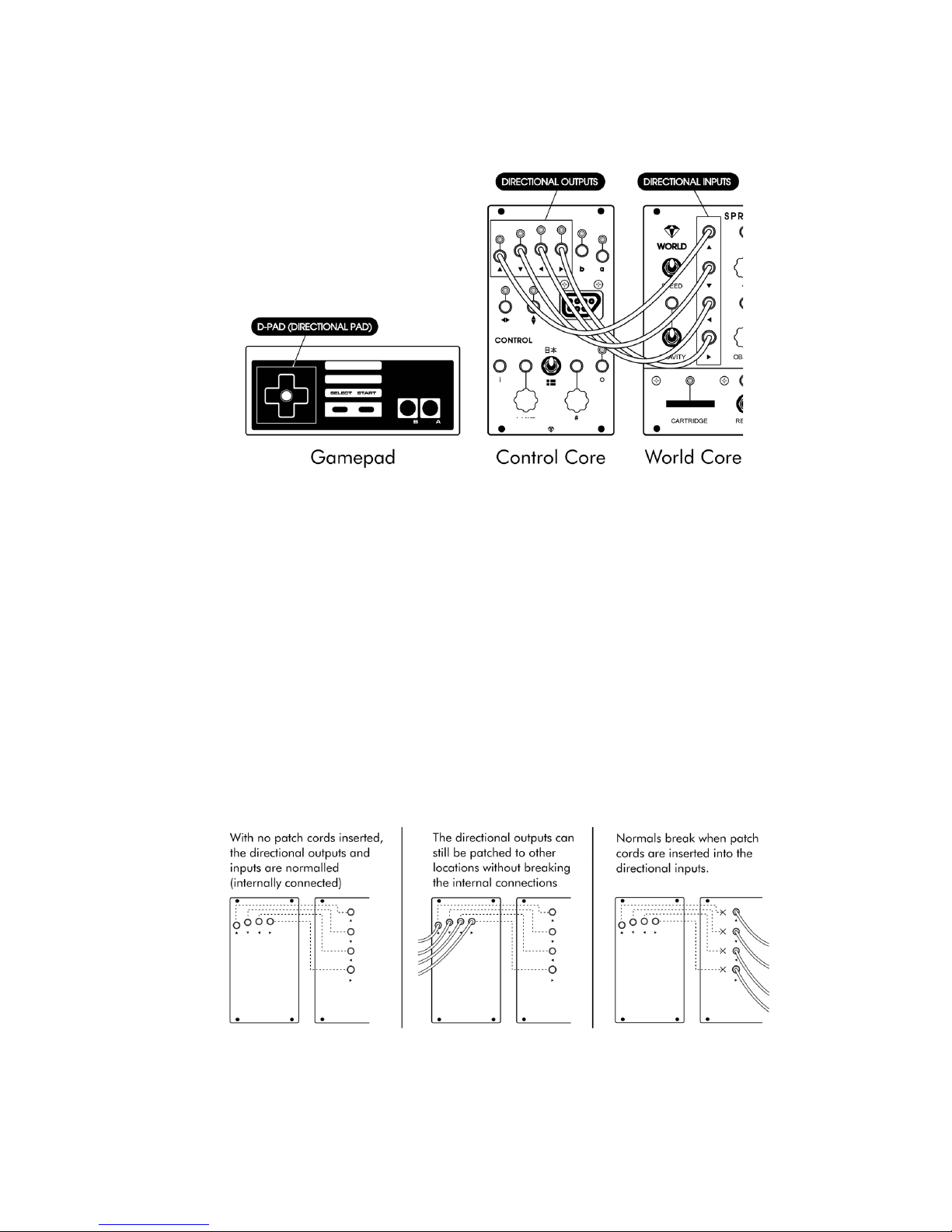
LINKING A CONTROL CORE
A CONTROL CORE can be used for many different purposes, but its
most basic application is controlling the movement of SPRITEs—small
graphical blocks that can be positioned anywhere on the screen. The
gamepad’s DIRECTIONAL PAD (“D-PAD”) generates GATEs from the
CONTROL CORE’S four DIRECTIONAL OUTPUTs (UP, DOWN, LEFT, and
RIGHT). By patching these outputs into the DIRECTIONAL INPUTs locat-
ed on the WORLD CORE, the gamepad can be used to freely move
SPRITE 1 around the screen.
9
If this is a little confusing right now, don’t worry; you’ll learn all
about controlling SPRITEs in CHAPTER 4. For now we’ll just say that the
patch above is a common “starting position” for creating more complex MING MECCA patches.
Because this patch is used so frequently, we’ve provided a way to
hardwire it internally using a technique called NORMALIZATION. This
automatically connects the DIRECTIONAL OUTPUTs to the DIRECTIONAL
INPUTs without the use of patch cords, allowing SPRITE 1 to be moved
by the gamepad without any set up.
10
d
No functionality is lost when using NORMALIZATION. The DIREC-
TIONAL OUTPUTs can still be routed to other locations as usual, and
the internal connections can be overridden by simply inserting a
patch cord into the corresponding DIRECTIONAL INPUT.
NORMALIZATION works using a mechanical switch inside the
DIRECTIONAL INPUTs. When no patch cord is inserted, the
switch is closed, making the connection to the DIRECTIONAL
OUTPUTs. When a patch cord is inserted, it physically lifts the
switch to override the connection.
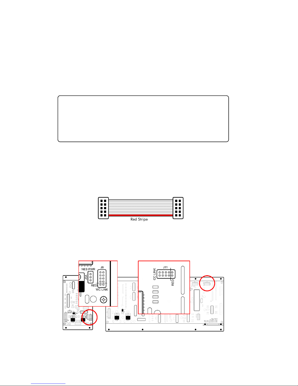
To enable NORMALIZATION, the two modules must be LINKED by
connecting their MOTHERBOARDs together. To LINK your modules,
first locate the 10-pin LINK CABLE that was included with your WORLD
CORE. Note the position of the cable’s RED STRIPE.
Now locate the CC LINK and WC LINK header connectors on the
WORLD CORE and CONTROL CORE MOTHERBOARDs.
11
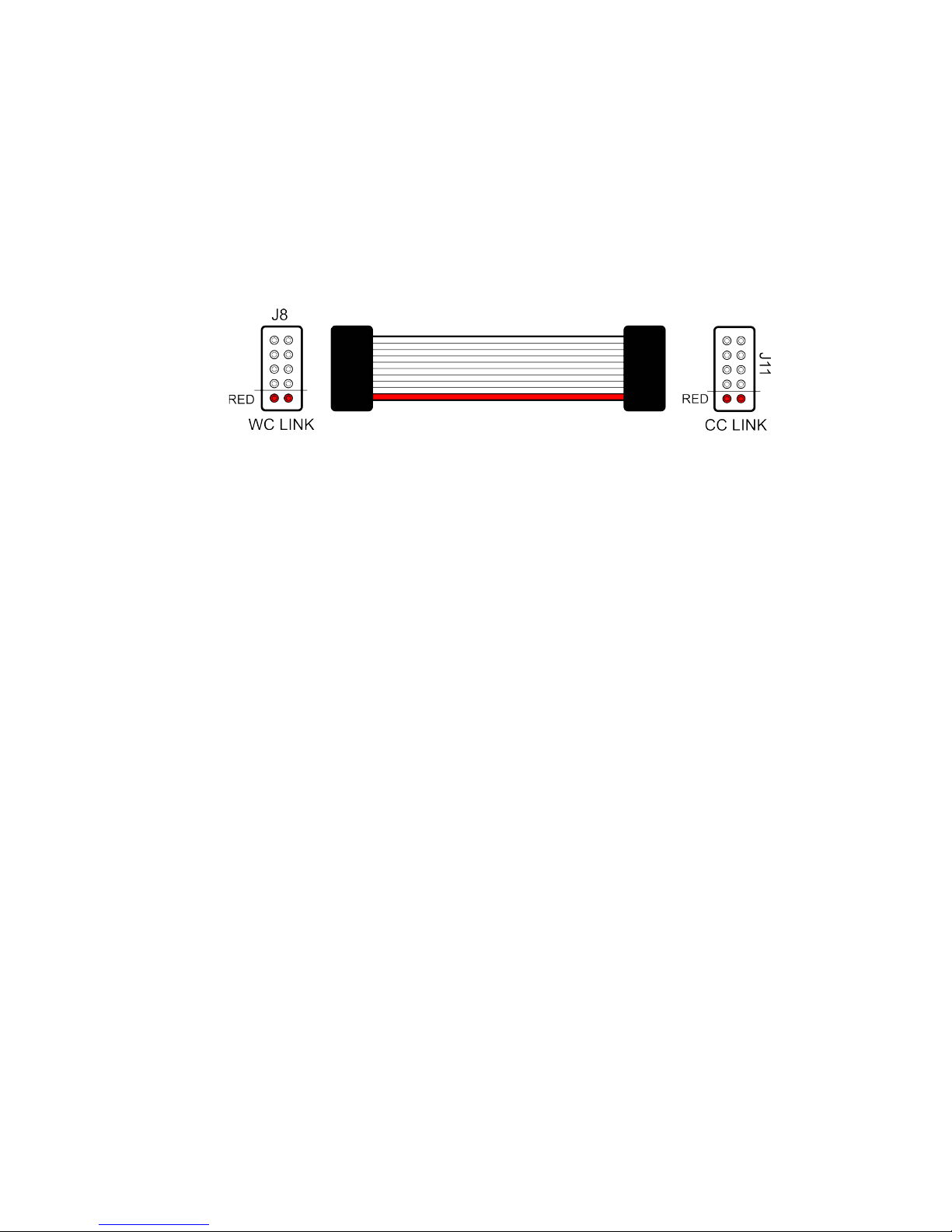
Position the cable’s RED STRIPE so that it aligns with the pins
marked RED on the WC LINK and CC LINK header connectors. Due to
its position on the MOTHERBOARD, you will have to rotate the cable
90 degrees to the left when connecting it to the CC LINK header on
the WORLD CORE.
Double-check the RED STRIPE alignment, and then firmly press
down on each side of the cable connector until the header pins are
fully covered. Your CONTROL CORE and WORLD CORE are now
LINKED. Only one CONTROL CORE can be LINKED to a WORLD CORE
at a time. If you ever decide you would rather keep them functionally
isolated, the modules can be UNLINKED by removing the cable.
CONFIGURING AND
CONNECTING POWER
MING MECCA modules are designed for use within EURORACK
modular synthesizer systems. In order to use your WORLD CORE
module you will need to install it in a EURORACK case and supply it
with EURORACK-compatible power. EURORACK cases usually have a
power supply and power distribution system built in.
12
d
Caution should be exercised when installing any new mod-
ule in your system. Although Special Stage Systems has taken
steps to protect your WORLD CORE from inverted polarity, it is
impossible to predict all potential scenarios given the open
nature of the EURORACK standard. Special Stage Systems
accepts no liability for damage to the WORLD CORE or to any
other connected hardware due to reversed, offset, or other-
wise incorrect power connection. Please follow this guide
closely and double-check the ribbon cable before applying
power to your modular.
13
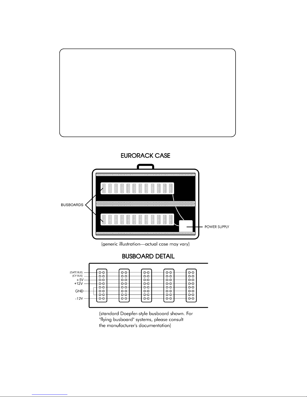
EURORACK modules receive power via ribbon cables that attach to
the case’s BUSBOARDS. Most BUSBOARDS use headers that are unkeyed, which means that it is possible to plug power in backwards. Accidentally inverting the polarity can damage not only the
reversed module, but any modules connected to the same BUSBOARD
as well.
CONNETING POWER
Before connecting power to your WORLD CORE, first verify that
your case meets the minimum requirements for use with MING MEC-
CA. You will need a minimum of 56HP (11.2”) of free horizontal space
to install the WORLD CORE, and an additional 14HP (2.8”) for the optional CONTROL CORE. Your case must also be sufficiently deep to
house the module’s internal circuitry. The WORLD CORE measures
1.98” deep, while the CONTROL CORE measures 1.75”.
Your power supply must be able to provide at least 250mA of current on the +12V rail. If you are also connecting a CONTROL CORE,
you will need an additional 210mA of current available for 460 mA
total.
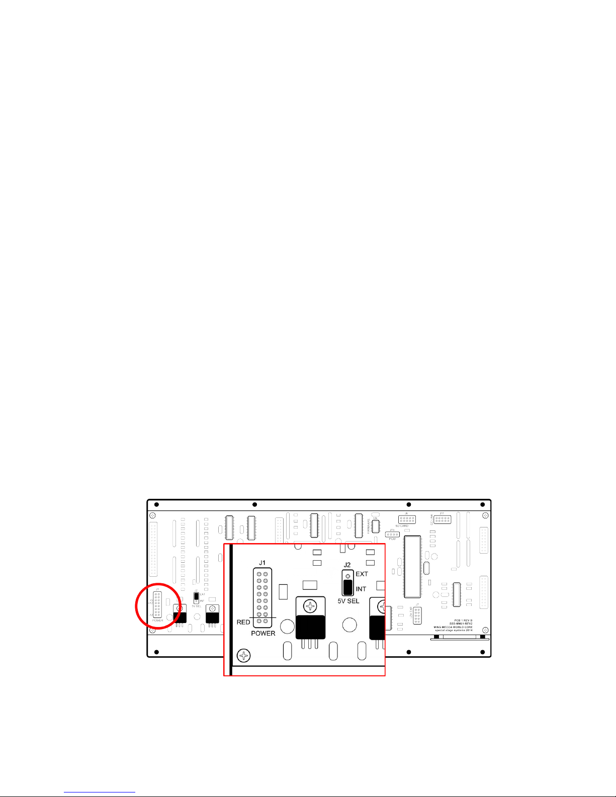
Now locate the 16-pin power connector on the MOTHERBOARD.
14
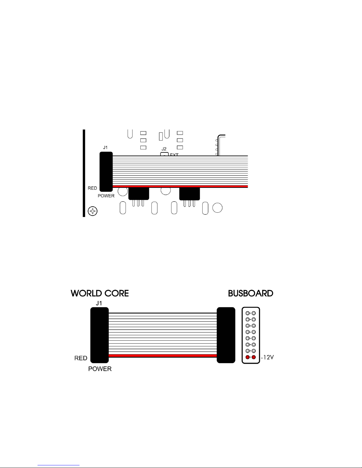
The 16-to-16 pin POWER CABLE should already be connected to
the module. Note the position of the cable’s RED STRIPE. Verify that
the RED STRIPE is aligned with the location marked “RED” on the power connector. If the cable is not properly aligned, remove and reposition it so that the alignment is correct.
Connect the other end of the cable to your power supply, making
sure that the RED STRIPE aligns with the -12V pins on the BUSBOARD
header.

15
d
If you are unsure about the orientation of your case’s BUSBOARD
headers, consult the manufacturer’s documentation for more information.
CONFIGURING THE +5V SUPPLY
By default, the WORLD CORE generates all the power it needs from
the +12V rail. The WORLD CORE can also be configured to use an
external +5V supply to power its digital components. Not all EURO-
RACK cases provide +5V power, and many that do are actually de-
rivative of the +12V supply. In EURORACK cases that provide truly independent +5V power however, configuring the WORLD CORE to use
the external supply can lessen the load on the +12V rail.
If you don’t know whether your case provides independent
+5V power, it’s best to leave the WORLD CORE in its default
configuration. The option to use an external +5V supply is for
advanced users who are looking to maximize the efficiency
of their system’s power supply.
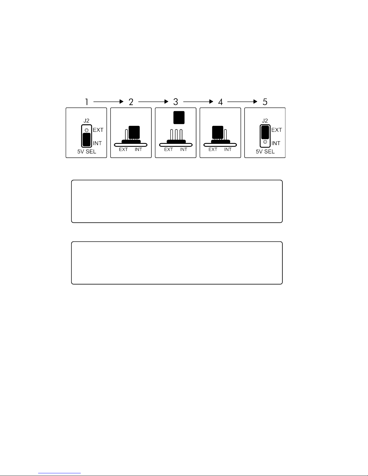
To configure the WORLD CORE for use with an external +5V power
supply, first locate the 5V SELECT JUMPER on the MOTHERBOARD.
16
d
d
Remove the jumper and reinstall it in the “EXT” position, as shown
in the diagram below.
WARNING: the 5V SELECT JUMPER must be installed in either
the “EXT” or “INT” position before applying power. Never at-
tempt to power the WORLD CORE with the 5V SELECT JUMPER
removed.
WARNING: do not configure the WORLD CORE for external
+5V power if your case does not have a working +5V rail. In-
stalling a WORLD CORE configured for external power in a
case that doesn’t supply +5V may damage the module.
The WORLD CORE will now use an external +5V supply for its digital components. Note that the +12V rail is still required in order to
power the analog sections of the MOTHERBOARD; always use a full
16-to-16 pin POWER CABLE when powering the module, regardless
of the 5V SELECT JUMPER setting.
17
CONNECTING A DISPLAY
Now that you’ve connected power to your WORLD CORE, you can
install the module in your case using the eight included screws. But
don’t turn on the power just yet; before using your module for the
first time, you’ll need to connect it to a compatible display.
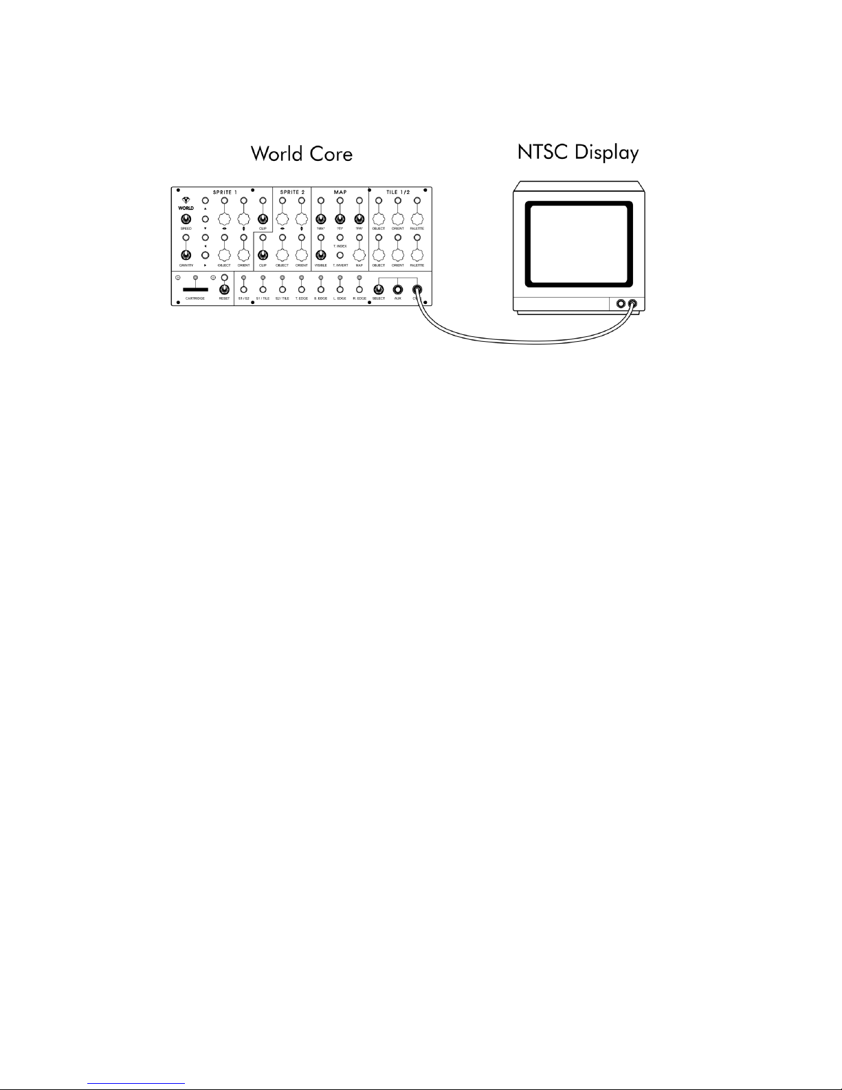
The WORLD CORE can be connected to any display that accepts
composite NTSC video. We recommend the use of a Cathode Ray
Tube (CRT) television or monitor. Although these displays are no
longer in production, they generally provide the best picture quality
and response time when dealing with analog composite video
sources like the WORLD CORE. If you do not have a CRT display
available, the WORLD CORE will also work with any modern display,
projector, or capture device that accepts composite video.
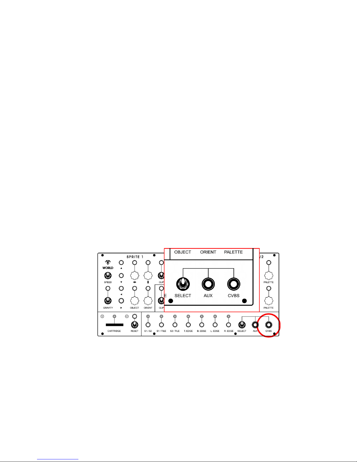
To connect the WORLD CORE to your display, locate the video output marked CVBS on the front panel. (CVBS is an initialism for composite video that stands for “Color, Video, Blanking, and Sync.”)
Connect a composite video (RCA) cable to the CVBS jack. Make
sure you don’t accidentally plug into the AUX jack instead. Now plug
the other end of the cable into your display’s video input.
18
Finally, make sure the SELECT toggle is in the upright position. This
toggle switch determines whether the CVBS jack will display the
WORLD CORE’s internal video output, or the signal patched into the
AUX video input. When set in the downward position, it selects the
AUX input, which will cause the WORLD CORE to display a blank
screen when nothing is connected to the AUX jack.
A NOTE FOR USERS IN PAL TERRITORIES
Although the WORLD CORE is currently NTSC only, there are several
workarounds available to PAL users:
• Use a multi-format CRT (recommended)
Many higher-end CRTs will display both PAL and NTSC video
sources natively.
• Use a modern display
Most composite-compatible projectors and LCD displays are
multi-format,but may introduce minor lag and ghosting.

19
d
• Use a video capture device
USB, FireWire, or Thunderbolt capture devices are usually
multi-format, but they can also introduce significant lag.
• Use an NTSC-to-PAL converter.
Dedicated boxes can be bought that convert NTSC to PAL. Depending on the quality of the unit, some image degradation
may be apparent as a result of the conversion process.
POWERING ON THE WORLD CORE
FOR THE FIRST TIME
You are now ready to turn on your WORLD CORE! Make sure your
display is turned on, and double-check the position of the SELECT
toggle (it should be in the upward position).
As you turn on your modular, watch the LED above the CARTRIDGE
SLOT. After a few seconds, the LED should flash once to indicate that
the WORLD CORE has passed its internal system check.
Immediately after the LED flashes, you should see a fast sequence
of rainbow bars on your display, followed by the Special Stage Sys-
tems boot logo.
If you do not see anything on your display, or the CARTRIDGE
LED fails to flash, turn off your modular immediately and pro-
ceed to the TROUBLEHSOOTING CHART in APPENDIX C.
Once the WORLD CORE has successfully booted, feel free to jump
right in and start playing with the controls. Don’t worry if some of
them seem unresponsive or don’t behave like you’d expect. The

20
WORLD CORE has a lot of settings that interact with each other in
complex and sometimes unpredictable ways. You can’t damage anything by using the controls, and as long as you stay within the EURO-
RACK power range (-12V to +12V), you can’t damage anything by
patching into the jacks either.
When you’re ready to learn more, reset your WORLD CORE (pull
the RESET toggle switch next to the CARTRIDGE SLOT downwards, and
release) and move on to CHAPTER 2.
 Loading...