

Page 1
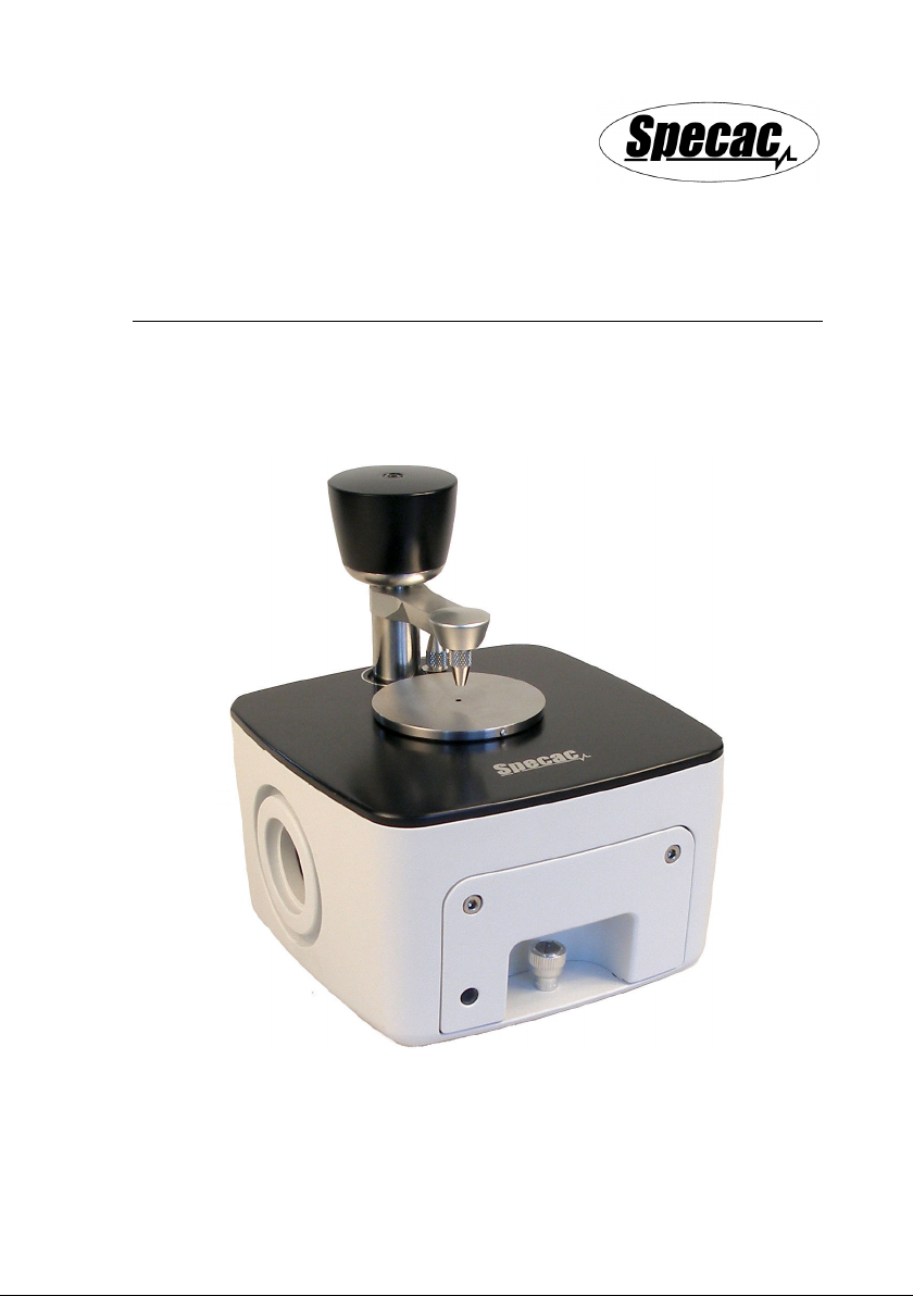
The Quest
Single Reflection ATR Accessory
User Manual
2I-10800-8
Page 2

Page 3

The Quest
Single Reflection ATR Accessory
User Manual
2I-10800-8
Page 4

User Manual
The Quest Single Reflection ATR Accessory
P/N GS10800
CONTENTS
1.
INTRODUCTION
2.
SAFETY CONSIDERATIONS
3.
CHECKLIST OF CONTENTS
4.
INSTALLATION USING BENCHMARK™ BASEPLATE
5.
ALIGNMENT PROCEDURE FOR QUEST ATR ACCESSORY
FITTING OF QUEST ATR CRYSTAL PUCK TO THE OPTICAL UNIT
FINE ALIGNMENT
SYNOPTI-FOCAL MIRROR SYSTEM
ALIGNMENT PROCEDURE
6.
PURGING THE QUEST ATR OPTICAL UNIT
FITTING THE PURGE BELLOWS (P/N
7.
QUEST ATR ANVILS AND CLAMP ANVIL ARM ASSEMBLY
CHOICE OF ANVILS AND THEIR USES
CLAMP ANVIL ARM ASSEMBLY
TORQUE LIMITER SCREW KNOB ASSEMBLY
8.
SAMPLING USING THE QUEST ATR ACCESSORY
COLLECTING ATR SPECTRA OF POW DER SAMPLES
COLLECTING ATR SPECTRA OF FLAT SOLID SAMPLES
COLLECTING ATR SPECTRA OF PELLET/BEAD SAMPLES
COLLECTING ATR SPECTRA OF FIBER SAMPLES
COLLECTING ATR SPECTRA OF LIQUID AND PASTE SAMPLES
THE VOLATILES COVER (P/N
THE SPECULAR REFLECTANCE PUCK (P/N
NOTES ON CLEANING
9.
QUEST ATR ACCESSORY PART IDENTIFICATION LIST
10.
QUEST ATR ACCESSORY SPARE PARTS
11.
QUEST ATR TECHNICAL SPECIFICATIONS
12.
QUEST ATR SERIAL NUMBERS
© February 2018 Specac Ltd. All rights reserved.
Benchmark and Brilliant Spectroscopy are trademarks of Specac Ltd.
Other product names mentioned herein may be trademarks
................................................................................. 3
................................................................. 5
.................................................................. 6
................................ 7
........................ 8
............... 8
............................................................................. 12
..................................................... 13
................................................................. 14
........................................... 19
GS10707) ................................. 21
....................... 22
................................................. 22
........................................................... 23
........................................ 25
.................................. 26
............................. 27
......................... 29
...................... 30
................................. 31
............... 33
GS10825) ............................................ 34
GS10816) ........................ 36
....................................................................... 38
........................... 44
........................................... 45
......................................... 46
......................................................... 47
of their respective owners.
2
Page 5

Quest Single Reflection ATR Accessory
1. Introduction
Thank you for buying a Specac product. We trust it will provide you
with invaluable and excellent service in use.
The Quest Single Reflection ATR Accessory is designed for the
quantitative and qualitative analysis of solids, powders, liquids, pastes
and gum-like samples using Mid IR spectroscopy at ambient
temperature and pressure conditions. Principally, ATR spectral
measurements at a nominal 45° incident angle are made, but specular
reflectance measurements at the same nominal incident angle can be
made using an optional specular reflectance puck assembly. Sufficient
sample is required to cover an ATR crystal surface offered from a
single crystal diamond, zinc selenide (ZnSe), germanium (Ge) and
silicon (Si) flat crystal top plate assembly (puck) options.
The Quest ATR Accessory is based upon Synopti-Focal technology –
an innovative synoptic focusing array of highly reflective gold coated
mirror only optics – in an optical unit that supports the interchangeable
ATR crystal puck assemblies. An IR light beam that is projected
towards the ATR crystal is presented at a nominal 45° angle of
incidence to the sample surface. As the optical unit of the Quest ATR
Accessory consists of mirrors as reflective components only, it allows
for as wide a range as possible of the spectral frequency throughput
for the specific ATR crystal puck assembly being used. For mid IR
spectral data the typical spectral range that can be collected for the
different ATR crystal puck types are as follows:
Diamond puck – 7,800cm-1 to 400cm-1 (AR coated crystal).
Diamond puck – 10,000cm-1 to 40cm-1 (Extended Range – non-AR
coated crystal).
ZnSe puck – 7,800cm-1 to 500cm-1. (AR coated crystal).
Germanium puck – 5,500cm-1 to 480cm-1. (AR coated crystal).
Silicon puck – 8,333 to 100cm-1. (Non-AR coated crystal).
As mentioned, there is also an option in use of the Quest ATR
Accessory for the spectral measurement of solid sample types such as
flat surface films by the specular reflectance technique. The ATR
3
Page 6
User Manual
crystal puck assembly is replaced with a puck assembly that has no
ATR crystal fitted to allow for the nominal 45° incident angle of light to
be projected directly to the solid sample surface.
An adjustable clamp arm assembly with a set load torque limiter screw
knob is permanently affixed to the optical unit. There is a choice of selflevelling flat or concave pellet compression head anvils to use with the
clamp arm assembly depending upon the sample type to be studied
using an ATR crystal puck assembly. (No anvil is used for specular
reflectance measurements of solid sample types.) The torque limiter
screw knob provides for a consistent and reproducible load to either
one of the flat or pellet anvils to enable excellent close contact of a
solid sample with the ATR crystal. In operation, the entire torque screw
knob is rotated until a sufficient load and hence pressure has been
applied to the sample. The torque screw knob will continue to rotate
when the set load is reached, but the drive connection slips and no
more force will be applied. A “clicking” sound with continual rotation of
the knob acts as the indicator when the set applied load has been
reached. When using the clamp arm assembly with a compression
head anvil for pressure application to solid sample types, the anvil
does not rotate against the sample. This ensures that heat is not
generated by friction which may cause changes to the sample, and the
sample is not displaced from the correct sampling position.
The optical unit of the Quest ATR Accessory can be supplied in a
variety of different top surface colours on a light grey optical unit. The
standard colour is black (B), but there are options of red (R), yellow
(Y), orange (O), green (G), aqua (A) and purple (P).
Quest ATR Accessory
4
Page 7

Quest Single Reflection ATR Accessory
2. Safety Considerations
With use of any spectroscopic accessory that involves the study of a
wide range of chemical samples, the associated risk in handling may
mostly be attributed to the specific sample type to be handled itself. As
far as it is possible you should follow a procedure for safe handling and
containment of the type of sample to be used.
With respect to safety of use specifically to the Quest ATR Accessory,
this uses different crystal materials for the ATR crystal puck
assemblies where a sample is bought into contact for analytical
spectroscopic study. As standard, Diamond (type IIIA), Germanium
(Ge), Zinc Selenide (ZnSe) and Silicon (Si) are the four crystal
materials of choice that can be used.
Caution: Out of these four different crystal types, ZnSe is
the most potentially hazardous material with respect to
toxicity risk in use and handling.
Diamond, Ge and Si crystal materials can be considered relatively safe
to use, although Ge and Si may be harmful to the body if ingested in
significant quantity. The general rule when working with any crystal
material (and sample) is to always wear gloves and safety gear (e.g.
safety spectacles) when handling to obviate the risk of contact with the
skin.
Provided with each crystal version of puck assembly is a window
material safety data sheet for the crystal material itself that can be
consulted for safe handling. A copy of each of these datasheets can
also be found in this Quest instruction manual in the Notes On
Cleaning Section found on pages, 40, 41, 42 and 43.
5
Page 8

User Manual
3. Checklist of Contents
The Quest ATR Accessory is provided in its own specific packaging.
Depending on which Quest ATR system (the colour of the optical unit
and a specific crystal puck assembly), has been ordered will determine
the items to check on delivery.
Please check for the following.
1 Quest ATR Accessory including optical unit (with top surface colour
of choice) and clamp arm and anvil assembly.
1 Stainless steel flat anvil P/N GS10820.
1 Stainless steel pellet anvil P/N GS10821.
1 Pair of purge bellows P/N GS10707.
1 Volatiles cover P/N GS10825.
1 ATR crystal puck assembly (choice of Diamond, ZnSe, Ge or Si
crystal puck assembly).
Any additional Quest ATR crystal pucks or specular reflectance puck
ordered with the accessory.
1 Ball driver 3.0mm (for optical unit cover plate removal).
1 Ball driver 2.5mm (for mirror adjustment in optical unit).
1 Benchmark™ baseplate for your FTIR spectrometer.
1 Instruction manual for Benchmark™ baseplate installation.
1 Instruction manual for Quest ATR Accessory.
1 Quickstart guide for Quest ATR Accessory.
Carefully remove your Quest ATR Accessory and ATR crystal puck
assembly(s) from the packaging in readiness for use.
6
Page 9
Quest Single Reflection ATR Accessory
4. Installation Using Benchmark™ Baseplate
1
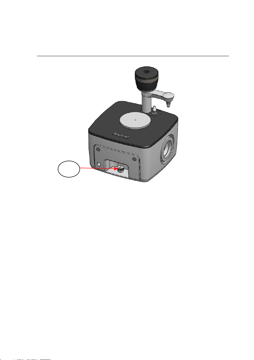
Fig 1.
Quest ATR Accessory – Optical Unit with Clamp Arm/Anvil
Assembly and ATR Crystal Puck Assembly
The Quest ATR Accessory is supported on a Benchmark™ baseplate
when installed into a spectrometer. The Benchmark™ baseplate
typically has three support pillars (one flat support pillar towards the
rear and two at the front with location pins) and a fourth front central
pillar into which the fixing thumb screw (1) of the Quest ATR optical
unit is tightened.
Note: It is normally best to install the Benchmark™ baseplate in
the spectrometer first before locating the Quest ATR
Accessory.
Fixing holes and studs in the Benchmark™ baseplate will vary
dependent upon the make and model of the spectrometer into which
the Quest ATR Accessory is to be installed. For details on how to
install your accessory in the spectrometer, refer to the Benchmark™
baseplate Installation Guide/User Manual supplied.
7
Page 10

User Manual
5. Alignment Procedure for Quest ATR
When you have installed the Quest ATR Accessory into your
spectrometer on its appropriate Benchmark™ baseplate, you should
check for alignment of the accessory. An overall spectral throughput of
light energy between 10% and 35%, dependent upon the ATR crystal
puck assemblies and spectrometer used should be achievable. The
Quest ATR Accessory with your choice of crystal puck will be supplied
having a preliminary factory alignment. On installation, some
transmitted energy should be recorded on the spectrometers
energy/light detector monitoring system, but it will be necessary to
maximize the optical throughput for any specific spectrometer by
adjusting the mirrors in the optical unit of the Quest ATR Accessory. To
carry out any alignment procedure one of the Quest ATR flat crystal
puck assemblies must be fitted to the optical unit.
Fitting of the Quest ATR Crystal Puck to the Optical Unit
Seven different versions of Quest ATR crystal puck assemblies can be
fitted to the optical unit. They are:
Quest ATR Diamond crystal puck, P/N GS10810.
Quest ATR Diamond extended range crystal puck, P/N GS10811.
Quest ATR ZnSe crystal puck, P/N GS10812.
Quest ATR Ge crystal puck, P/N GS10813.
Quest ATR Si crystal puck, P/N GS10819.
Quest ATR Diamond crystal puck with diamond like carbon (DLC)
coating, P/N GS10826.
Quest ATR Diamond extended range crystal puck with diamond like
coating (DLC), P/N GS10827.
The ATR crystals of these puck assemblies have an antireflection (AR)
coating on their underside surfaces for improved light throughput
characteristics, except the extended range diamond crystal pucks
P/N’s GS10811 and GS10827, and the silicon puck P/N GS10819.
Serial number and puck crystal identification labels are affixed to the
underside surface of the puck assembly. (A note of the serial number
of your crystal puck assembly can be made on page 47 of this user
instruction manual for your reference records.)
8
Page 11

Quest Single Reflection ATR Accessory
Diamond Like Carbon (DLC) Coating on Puck Assemblies
The two diamond AR coated and extended range crystal puck
assembly options as P/N’s GS10826 and GS10827 are provided with a
protective DLC coating over the surrounding stainless steel circular
puck top surface to the ATR crystal.
Note: The diamond ATR crystals of these Quest ATR crystal puck
assemblies do not have a DLC coating applied to the surface.
The DLC coating is a durable, chemically resistant layer of 7 microns
thickness covering the stainless steel puck surface. The diamond ATR
crystal itself used in the puck assembly for any spectral analysis from
actual sample contact is a highly chemically inert substance,
impervious to attack from a very wide range of chemical types that can
be studied. Applying an additional DLC coating protective layer to the
surrounding and supporting stainless steel puck of the diamond ATR
crystal extends the chemical resistance properties of the puck
assembly overall. Typically, 1 mol/L concentration hydrochloric acid
solution (HCL – pH0) and 1 mol/L concentration sodium hydroxide
solution (NaOH – pH14) have little or no effect when contacting the
DLC coated stainles steel puck assembly surface continuously for an
hour at ambient conditions.
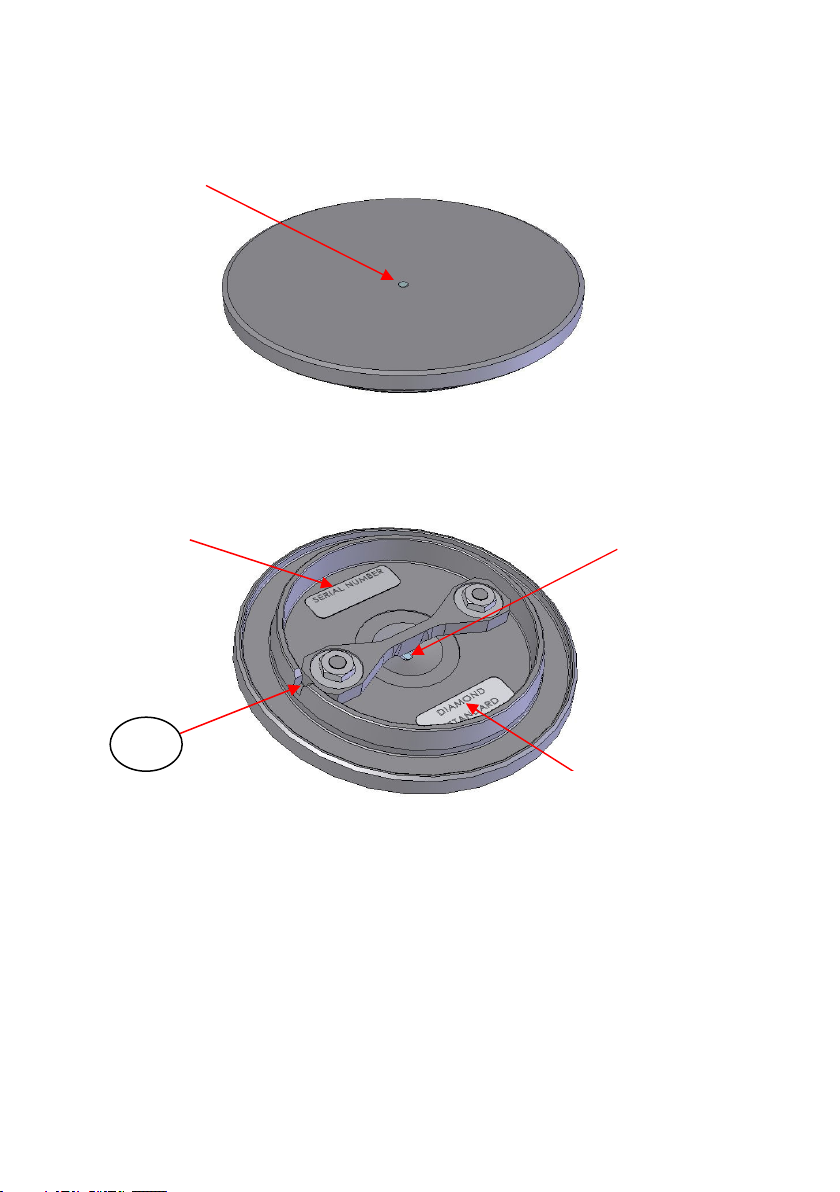
Quest ATR Crystal Puck Assemblies Identification
Top and underside views of the Quest ATR crystal puck assemblies
using the diamond crystal puck P/N GS10810 as an example are
shown as Figs 2 and 3. (ZnSe, Ge and Si top plates are similar.)
The top surface area of the Quest ATR optical unit for positioning of
the ATR crystal pucks, is shown as Fig 4.
9
Page 12
User Manual
10
ATR Crystal
Fig 2. Top view of Quest ATR Diamond Crystal
Serial Number Label
Puck Assembly
ATR
Crystal
2
Crystal Puck
Identification Label
Fig 3. Underside view of Quest ATR Diamond Crystal
Puck Assembly
Note: The fixing nuts for the underside support bracket of the puck
assembly will be covered with tamperproof red marking strips
and these fixing nuts should never be touched. Any attempt to
adjust these nut fixings will be identifiable and will invalidate any
warranty for the puck assembly.
Page 13
Quest Single Reflection ATR Accessory
3
4
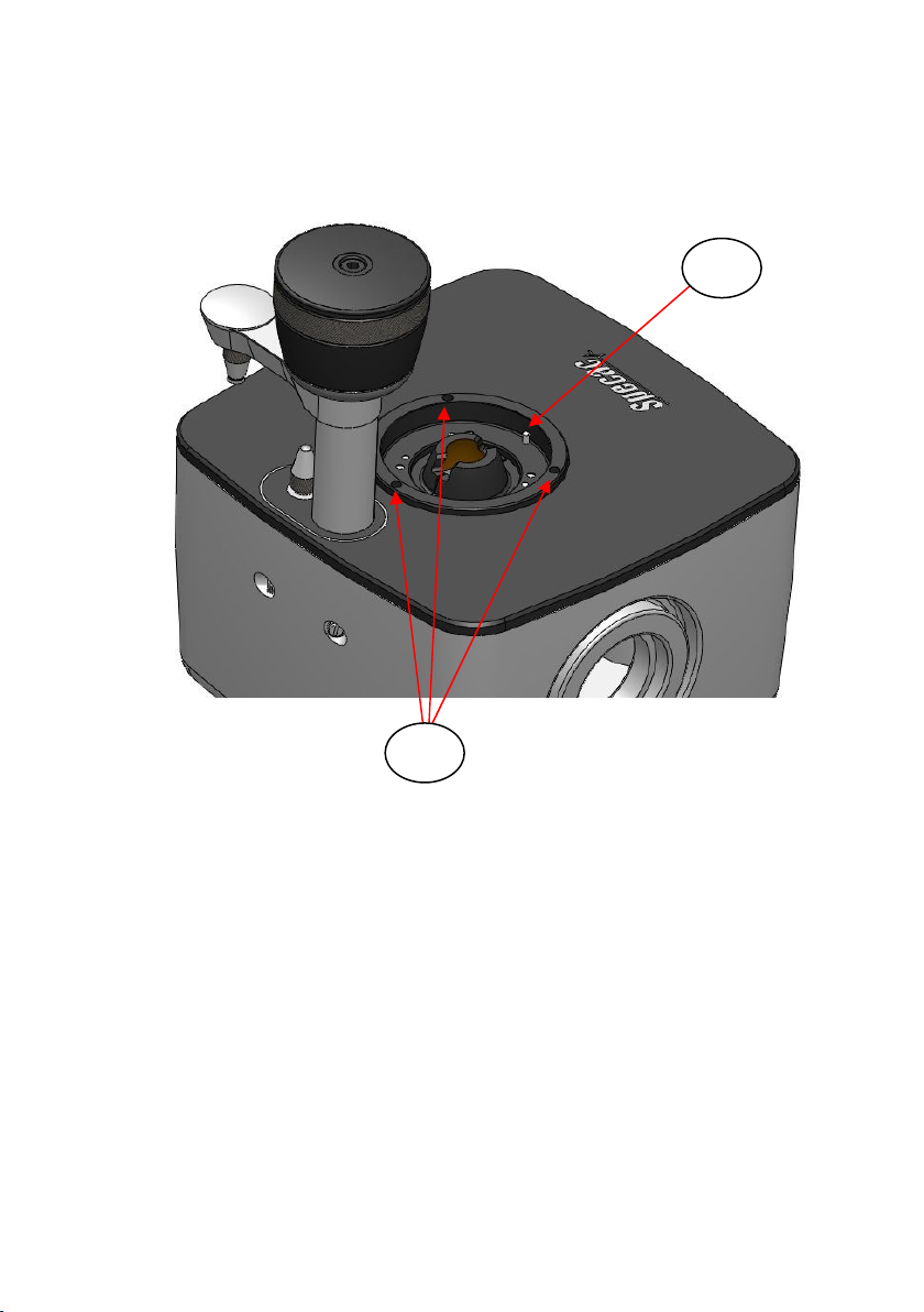
Fig 4. Top view of Quest ATR Optical Unit showing location area
for the Crystal Puck Assemblies
The ATR crystal puck assemblies will fit onto the top surface area of
the Quest ATR Accessory in one orientation only. Align the location
slot (notch) (2) on the underside of the crystal puck (see Fig 3.) with
the location pin (3). The location slot (2) of the ATR crystal puck must
be facing towards the front of the Quest ATR Accessory where the
thumbscrew fixing (1) is located. (See Fig 1.) Allow the three magnetic
circular spot catches (4) to engage to the underside circumference
surface of the ATR crystal puck to hold it securely in position. To
remove and swap over with any other ATR crystal puck assembly, just
grip the sides of the ATR crystal puck and pull it up to release the hold
of the magnetic catches.
11
Page 14
User Manual
12
Fine Alignment
With a Quest ATR crystal puck assembly in position on the optical unit
and when this completed assembly is installed in the spectrometer on
an appropriate Benchmark™ baseplate, the Quest ATR Accessory can
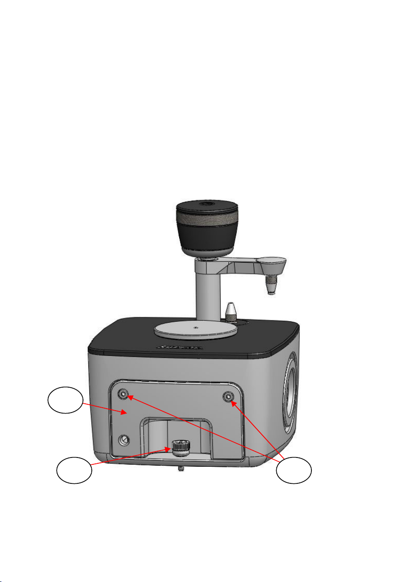
be finely aligned. The optical unit front cover plate (5) is removed by
undoing the two captive cover plate screws (6) (see Fig 5.) using the
3mm ball driver supplied. The front cover plate (5) is pulled up and
forward over the fixing thumb screw (1) for its removal to gain access
to the internal mirrors for adjustment.
5
6 1
Fig 5. Quest ATR - Front Cover Plate Removal
Page 15
Quest Single Reflection ATR Accessory
Synopti-Focal Mirror System
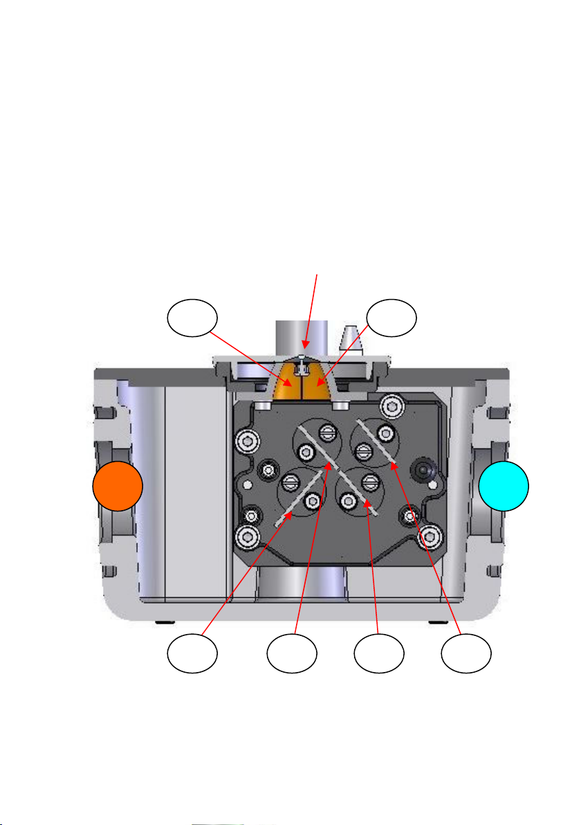
The Quest ATR Accessory is based upon Synopti-Focal technology
which uses an innovative synoptic focusing array of highly reflective
gold coated mirrors for the optical pathway when a different ATR
crystal puck assembly is positioned for use on the optical unit. The
mirror arrangement for an IR beam passage through the Quest ATR
Accessory can be seen from the cutaway front view in Fig 6.
ATR Crystal Puck Assembly on Top Plate
M5 M4
Fig 6. Cutaway front view of Quest ATR Accessory showing the
13
M6 M3 M1 M2
Synopti-Focal arrangement of mirror components
S D
Page 16

User Manual
14
The Quest ATR Accessory can be used in any standard spectrometer
system irrespective of the beam direction of light through the sample
compartment from source to detector. However, for explanation of the
internal IR beam passage through the Quest ATR Accessory the
sequential labeling of mirror components has been assigned for a
spectrometer that has an IR beam running through the sample
compartment from a source (S) on the right-hand side towards a
detector (D) on the left-hand side. For this right to left beam passage
configuration the IR beam sequence is as follows:
S, M1, M2, M3, M4 – ATR Crystal – M5, M6, D.
The mirrors M1, M2, M3 and M6 are flat, gold coated mirrors. (M6 is a
slightly larger sized mirror, wider and longer than the M1, M2 and M3
mirrors, to eliminate any potential stray light throughput.) Mirrors M4
and M5 are aspheric, focusing gold coated mirrors. The angle of
incidence for the IR light beam when it interacts at the crystal/sample
interface surface is nominally set at 45° for the ATR effect.
Alignment Procedure
When the front cover plate (5) has been removed (see Fig 5.) to gain
access to the internal M1, M2, M3 and M6 flat mirrors frame assembly,
the mirrors M1, M3 and M6 only in the optical unit can be adjusted for
rotation and tilt for alignment, to optimise the light throughput of the
Quest ATR Accessory for your spectrometer system.
Note: The flat mirror M2 and the hemispherical mirrors M4 and M5 do
not require adjustment for the alignment procedure. A cover has
been placed over the rotation adjustment screw for mirror M2
(see Fig 6.) to prevent access for accidental movement.
A 2.5mm ball driver tool has been supplied for adjustment of the
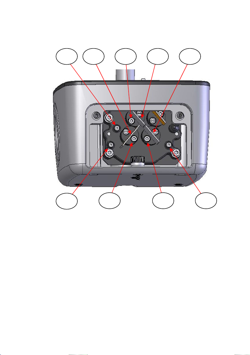
rotation and tilt screws for the mirrors M1, M3 and M6. Please refer to
Fig 7. which identifies the rotation and tilt screws that need to be
adjusted for the mirrors M1, M3 and M6.
Page 17
Quest Single Reflection ATR Accessory
9 10 M3
M6 M1
7
8 12 11
Fig 7. Access to Mirrors M1, M3 and M6 - Cover Plate Removed
The grub screw (7) allows for rotation of the M6 mirror and the cap
head screw (8) allows for tilt of the M6 mirror, as fitted to the main
mirror frame assembly.
The grub screw (9) allows for rotation of the M3 mirror and the cap
head screw (10) allows for tilt of the M3 mirror, as fitted to the main
mirror frame assembly.
The grub screw (11) allows for rotation of the M1 mirror and the cap
head screw (12) allows for tilt of the M1 mirror, as fitted to the main
mirror frame assembly.
15
Page 18

User Manual
16
To begin any alignment, first establish that there is a throughput of IR
light radiation passing through the system from (S)ource to (D)etector
with the Quest ATR Accessory installed correctly on it baseplate in the
spectrometer sample compartment and with an ATR crystal puck
assembly in position on the optical unit.
1. Using the 2.5mm ball driver tool (supplied), the alignment
procedure initially involves rotational movement of the mirrors M6,
M3 and M1 in this sequential order. The grub screws, (7), (9) and
(11) are turned to make the rotational adjustment for each mirror.
One at a time, very gently rotate each screw, (7), then (9) and
finally (11), clockwise or anticlockwise to achieve a maximum
energy signal reading. If you travel through a maximum energy
position by, say, continued clockwise rotation, then turn the screw
anticlockwise to bring back to the maximum point again. (And vice
versa).
2. Having achieved a maximum throughput reading from rotation of
the M6, M3 and M1 mirrors from step 1, now use the 2.5mm ball
driver tool in the cap head screws (8), (10) and (12) in turn for
these three mirrors (in the same sequence) for their tilt adjustment
position by turning the screws similarly clockwise or anticlockwise
to maximise the energy.
Having optimised all three mirrors M6, M3 and M1 for both their
rotation and tilt settings for optical alignment, there is likely to be an
overall improvement in the light throughput energy value for the Quest
ATR accessory. Specac would recommend though that a second
“iteration” or sequence of rotation and tilt adjustments for these three
mirrors is carried out to optimize the energy throughput further for the
Quest ATR Accessory. Therefore, repeat the mirror adjustment steps 1
and 2 again.
When satisfied after one (or two) adjustment sequences have been
carried out that an acceptable throughput energy has been
established, the alignment procedure has been completed and the
front cover plate (5) can be repositioned onto the optical unit.
Page 19

Quest Single Reflection ATR Accessory
For some spectrometer configurations, if the Benchmark™ baseplate
is mounted on a rail or is movable in the spectrometer, then an overall
energy throughput may be improved by moving the Quest ATR
Accessory on the Benchmark™ baseplate to find the best position
where the transmission energy throughput is at a maximum. Firmly
secure the Benchmark™ baseplate with the Quest Accessory into this
new position if an improvement has been gained.
Note: In some spectrometers it may be necessary to remove the
Quest ATR optical unit before securing the baseplate. Where
this is the case, ensure that the Benchmark™ baseplate does
not move when removing the Quest ATR optical unit.
Procedure to Follow from Any Accidental Mis-Alignment
During an alignment, if a mistake is made and no signal response from
the detector of the spectrometer can be obtained, then it may be
possible to recover the situation for a partial, visual rough re-alignment
of the mirror optics M1, M3 and M6. This will re-establish a small
energy level through the system to reach the detector and allow for the
correct alignment procedure to be followed again to optimise the light
throughput.
Note: The following procedure can also be adopted if any Quest ATR
Accessory to be used is ever found to be out of alignment when
installed into a spectrometer system and there is no register of
an energy throughput to the detector. Mirror M2 should never
need to be adjusted in any alignment procedure.
1) With the front cover plate (5) removed from the optical unit to gain
access to the mirror frame assembly, also remove any crystal puck
assembly from the top of the optical unit and remove the Quest
optical unit from the Benchmark™ baseplate.
2) Using the 2.5mm ball driver tool in the screws (8), (10) and (12),
adjust all three mirrors M1, M3 and M6 ONLY for their angle of tilt
such that these mirror surfaces are normal (i.e. at a 90° right angle)
with relation to the back plane of the main mirror mount frame
assembly affixed to the rear of the optical unit.
17
Page 20

User Manual
18
3) Using the 2.5mm ball driver tool in the grub screw (9) to rotate mirror
M3 and in the grub screw (11) to rotate the mirror M1, adjust both
mirrors to form a straight line for both of their mirror surfaces. Refer
to Fig 6 to indicate how they need to be roughly aligned to form a
straight line orientation.
4) Mirror M6 now needs to be adjusted for its rotation using the 2.5mm
ball driver in the grub screw (7) such that its surface is similar in
angular relation to the straight line formed by the two mirrors M3 and
M1 as seen at Fig 6. An indication that a correct rotational angle for
mirror M6 has been achieved is when the grub screw (7) is proud of
its mirror carriage frame assembly housing by circa 2mm. This depth
indication for the grub screw (7) position can be observed looking
through the aperture port (16) on the left-hand side of the optical
unit.
5) With the three mirrors M1, M3 and M6 now roughly positioned for
their tilt and rotation angles, the optical unit can be placed back onto
the Benchmark™ baseplate and the crystal puck assembly is
repositioned on top of the optical unit to complete a beam path for
light to travel through the Quest ATR accessory.
6) Set up the IR spectrometer to record an energy throughput level at
the detector. Having followed steps 2) to 5) from the procedure
above, there should now be some energy level indication (however
small), at the detector after passage of light through the Quest ATR
Accessory and so the correct fine alignment procedure can now be
followed starting with further rotation of mirror M6 as described from
step 1) on page 16 of this instruction manual. However, even if there
is still no signal after the procedural steps 2) to 5) have been
completed (pages 17 and 18), then turning the grub screw (7) for
rotation of the mirror M6 (first one way and then the other), at this
stage now should lead to the energy level signal returning and for
progression to an optimum alignment.
Page 21
Quest Single Reflection ATR Accessory
6. Purging the Quest ATR Optical Unit
When the Quest ATR Accessory has been installed and aligned in the
spectrometer there is an option for purging the Quest ATR optical unit
if this is necessary.
5
13
Fig 8. Aperture Ports and Purge Connection on the
Quest ATR Optical Unit
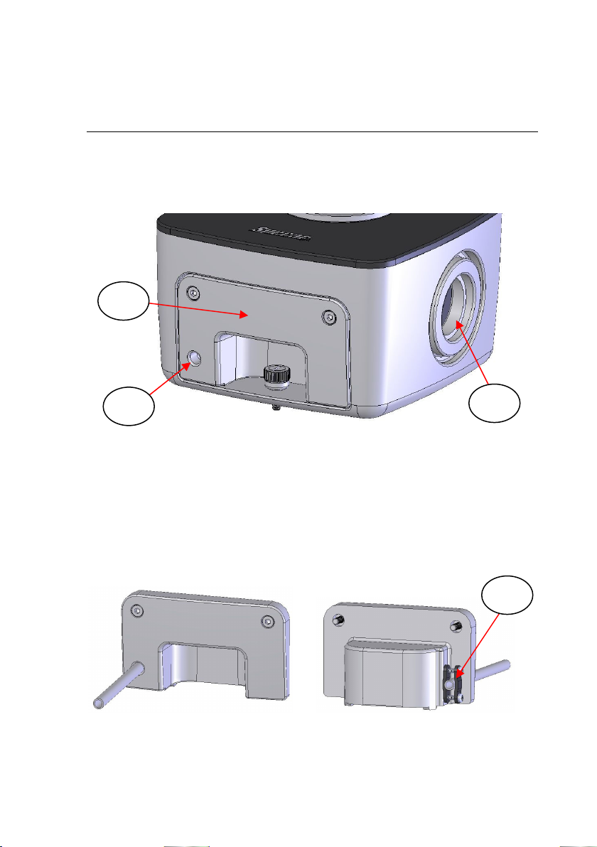
On the front cover plate (5) there is a small hole (13) into which 1/4”
O.D. hard plastic tubing can be inserted to provide a gas supply such
as N2 that creates a purged environment within the Quest ATR optical
unit. The tubing is introduced through the front of the hole (13) and is
held fast by two small curved grip plates (14). (See Fig 9.)
Fig 9. Front Cover Plate with Purge Tube – Front and Back Views
19
16
14
Page 22
User Manual
20
To introduce any tubing the front cover plate (5) is removed from the
optical unit. The screws holding the two curved grip plates (14) are
loosened to allow the open end of the tubing to pass through the grips,
which has been introduced into the hole (13) from the front side of the
cover plate. When a small length of tubing has passed through
between the curved grips (14) their screws are retightened to hold the
tubing firmly into position. The front cover plate (5) with attached purge
tubing can now be refitted to the optical unit.
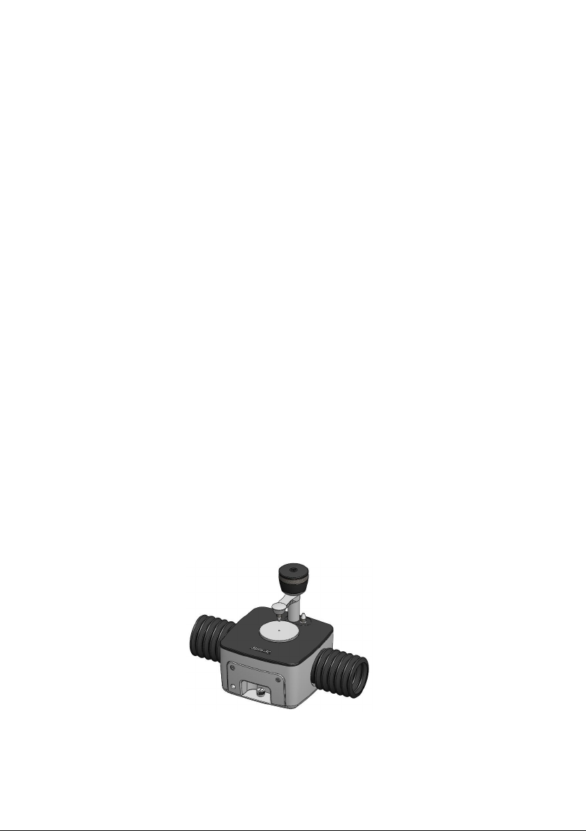
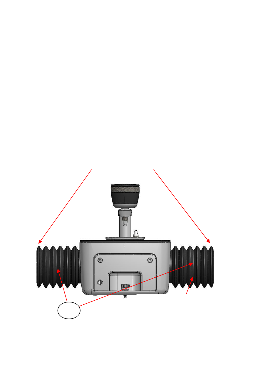
To help maintain a purged environment within the optical unit from
introduction of a gas via the attached purge tubing, a pair of purge
bellows (15) (P/N GS10707) have been supplied with the Quest ATR
Accessory for attachment to the optical units two aperture ports (16).
(See Figs 8 and 10.)
Faces of the purge bellows to be a flush fit with the inlet and outlet
bulkhead faces of the spectrometer sample compartment
15
To shorten length cut
between a groove
Fig 10. Quest ATR Accessory fitted with Purge Bellows
Page 23

Quest Single Reflection ATR Accessory
The purge bellows (15) grip fit between the circular recess and around
the circumference protrusion part of the aperture ports (16). They fit
the aperture port from one end only of their design as seen in Fig 10.
The purge bellows (15) bridge any gap between the optical unit and
the spectrometer sample compartment bulkheads from the (S)ource
and to the (D)etector and thus help to contain any purged environment
created within the optical unit whilst installed into the spectrometer
sample compartment. If the gap/distance between the optical unit and
bulkhead is small, the purge bellows can be cut to size for a better
compressible fit. It is best to cut all the way around and in between one
of the ridged grooves in the purge bellows moulding itself when
shortening the length for fit.
Tip: It is recommended that purge bellows (15) are fitted during use to
help stabilize the spectrometer/instrument background even if
purging is not to be carried out.
Fitting the Purge Bellows (P/N GS10707)
1. With the Benchmark™ baseplate secured and the Quest ATR
Accessory in position, measure the distance between the
spectrometer source and detector bulkhead/side walls and the side
end faces of the Quest ATR optical unit. (This is dimension “‘X”).
2. Using a sharp blade, cut lengths of the flexible purge bellows (15)
which are equivalent to the measured length (“X”) allowing for an
additional 10mm for each length to cut. (e.g. X + 10mm.)
3. Unscrew the Quest ATR optical unit fixing thumb screw (1) from
the Benchmark™ baseplate and remove the Quest ATR
Accessory from the sample compartment.
4. Fit the shortened flexible purge bellows (15) over both end
apertures (16) on the Quest ATR optical unit.
5. Replace the Quest ATR Accessory with the fitted purge bellows
(15) back onto the Benchmark™ baseplate. Ensure that the
compressed purge bellows (15) are not obstructing the optical
beam and retighten the fixing thumb screw (1) to secure the Quest
ATR Accessory back into position.
21
Page 24
User Manual
22
Anvil
Description
Sample Type / Use
7. Quest ATR Anvils and Clamp Arm Assembly
Choice of Anvils and their Uses
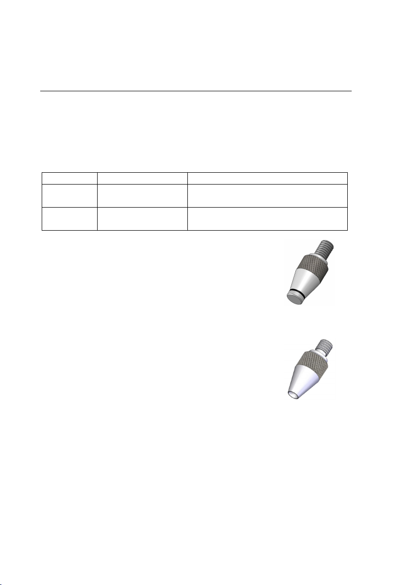
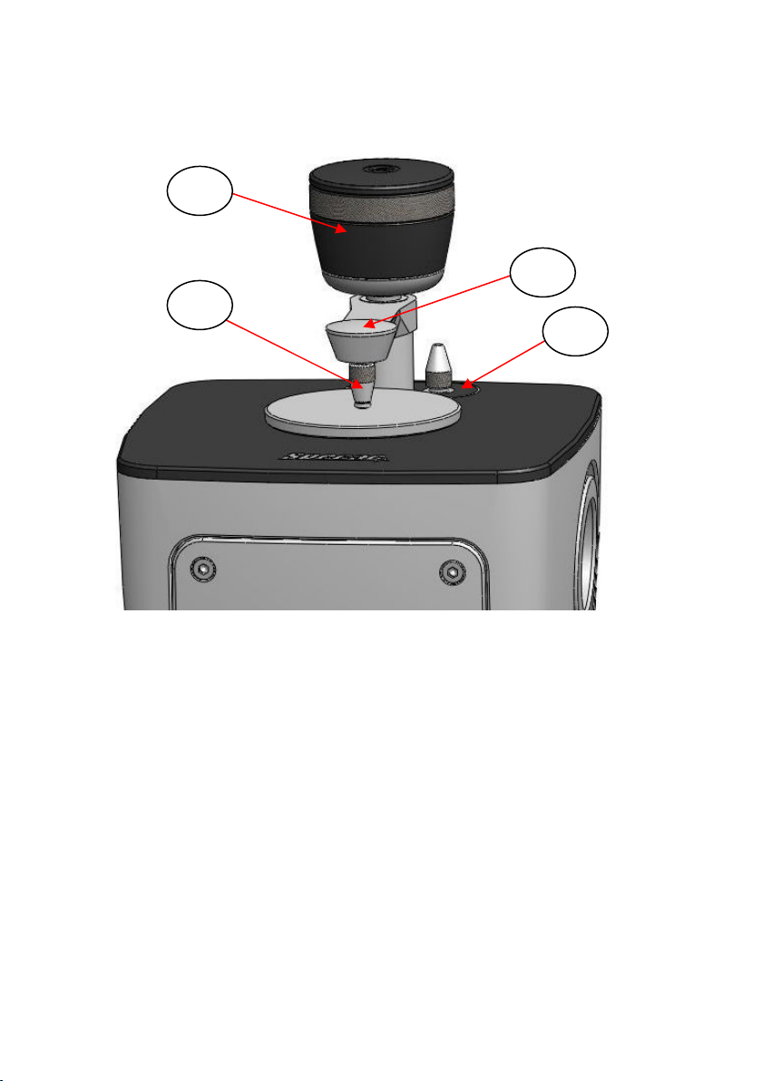
There are two different compression head anvils (17) that can be used
with the Quest ATR Accessory when fitted to the clamp arm assembly
(18). The anvil type and its uses are tabulated as follows:
GS10820 Stainless Steel
Flat
GS10821 Stainless Steel
Pellet
Self Levelling Flat Anvil P/N GS10820 (Fig 11.)
The stainless steel flat anvil P/N GS10820 has a self
levelling surface head and should be used generally
for all solid and powder samples to bring the sample
into good contact with any of the Quest ATR
diamond, ZnSe, Ge or Si crystal puck assemblies. Fig 11.
Pellet Anvil P/N GS10821 (Fig 12.)
The stainless steel pellet anvil P/N GS10821 has a
concave recessed surface head designed to take
round shaped samples such as polymer beads.
Relatively soft irregular shaped samples can be
used with this anvil on any of the Quest ATR Fig 12.
diamond, ZnSe, Ge or Si crystal puck assemblies,
but hard or very hard samples should be used with diamond only.
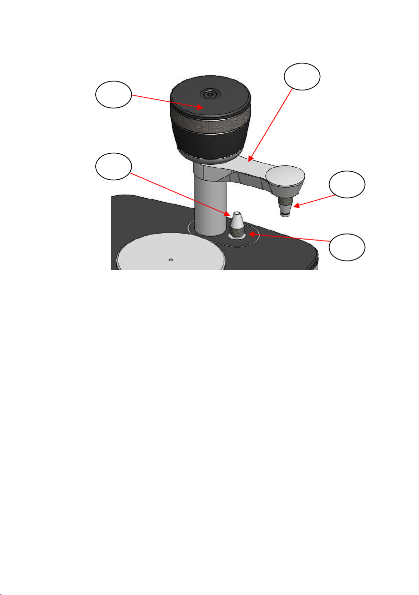
Either the flat or the pellet anvil (17) is fitted to the clamp anvil arm
assembly (18) by the screw threading on the anvil. For storage of the
anvil (17) that is not fitted to the clamp anvil arm, there is a threaded
location port (19) by the clamp arm assembly support post.
(See Fig 13. – the flat anvil is in the clamp anvil arm assembly and the
pellet anvil is in the storage port.)
Solids, films and powders
Polymer beads, softish irregular
shaped solids
Page 25
20
17
Quest Single Reflection ATR Accessory
18
17
19
Fig 13. Anvil in Clamp Anvil Arm Assembly and in Storage Port
Clamp Anvil Arm Assembly
When using the Quest ATR Accessory, a liquid or solid sample is
placed onto the crystal surface area of the flat ATR crystal puck
assembly being used to obtain an ATR spectrum for the sample.
Particularly for solid samples, the best ATR spectra are produced
when the sample is in close contact with the ATR crystal, so it is
recommended to use the clamp arm assembly (18) of the Quest ATR
accessory fitted to the optical unit. In use this way, a load can be
applied to the solid sample from the appropriate flat or pellet
compression head anvil (17) fitted in position, to force the sample into
good and close contact with the diamond, ZnSe, Ge or Si ATR crystal.
The clamp arm assembly (18) rotates on it support post for positioning
of the arm assembly. For application of a load force onto the ATR
crystal puck the clamp arm (18) is rotated to a central click stop
position pointing towards the front of the Quest ATR optical unit seen
in Fig 14. This is known as the “sampling” position.
23
Page 26
User Manual
24
20
18
17
19
Fig 14. Clamp Arm Assembly with Flat Anvil in Sampling Position
If the clamp arm assembly is not required for sampling it can be rotated
to a “parked” position to either the left or right side of the central post.
As seen in the example image for Fig 13. the clamp arm assembly (18)
has been rotated to the right side of the optical unit and is positioned
above the screw threaded port (19) for storage of an anvil (17).
When turning the clamp arm assembly (18) from the parked to
sampling position, the height level of the anvil (17) pressing face must
be sufficiently clear from the crystal surface to place a sample. The
anvils height position is controlled by rotation of the torque limiter
screw knob assembly (20). In Fig 14. the flat anvil (17) is shown being
forced down onto the crystal puck from clockwise rotation and
tightening of the torque limiter screw knob (20).
Page 27

Quest Single Reflection ATR Accessory
Torque Limiter Screw Knob Assembly
The Quest ATR clamp arm assembly (18) is provided with a special
built in torque limiter screw knob assembly (20). (See Figs 13. and 14.)
For solid sampling, an appropriate anvil (17) is fitted in position. A solid
sample is placed upon the diamond, ZnSe, Ge or Si ATR crystal of the
crystal puck assembly being used and the clamp arm assembly is
positioned towards the front of the optical unit with the anvil (17)
pressing surface at a suitably clear distance from and over the sample,
in readiness for turning the torque limiter screw knob (20) to bring the
anvil (17) down and into contact with the sample.
With an appropriate anvil (17) fitted, the torque limiter screw knob (20)
is turned in a clockwise fashion to provide a pre-determined set
pressure (40lbs load spread over the anvil face), which is transferred
to the sample. In operation, the entire torque limiter screw knob (20) is
rotated until a sufficient load and hence pressure has been applied to
the sample which is in turn forced into close contact with the surface of
the ATR crystal.
The torque limiter screw knob (20) will continue to rotate if being turned
when the set load is reached, but the drive connection slips and no
more force will be applied. A “clicking” sound with continual rotation of
the knob acts as the indicator when the set applied load has been
reached.
25
Page 28

User Manual
26
8. Sampling Using the Quest ATR Accessory
Important Note for Usage!
The diamond, ZnSe, Ge and Si crystals in the Quest ATR crystal puck
assemblies have a specific hardness and chemical resistance and
should be treated accordingly. The crystals have been sealed into
position to the stainless steel top plate mounting using Indium material.
Check on the chemical nature of a sample before potentially damaging
materials are brought into contact with the ATR crystal and the Indium
seal.
Be careful not to put a “point load” on the ATR crystal, particularly with
the ZnSe, Ge and Si crystal materials, from hard or abrasive samples.
When using samples such as rubbers and soft polymer sheeting etc,
there should be no problem and normal anvil pressures may be used.
The measurement of thin films on plastic substrates should present a
minimal risk for crystal damage, but care should be taken if the
substrate material is hard and metallic in nature.
Apply pressure from the torque limiter screw knob (20) by turning it
gradually. For some sample types, if there is a risk of damage to the
ATR crystal, it is advisable to try and acquire an infrared spectrum to
see if an acceptable load has already been applied for sufficient
sample contact, before the maximum load setting has been reached
from clockwise rotation of the torque limiter screw knob.
Preparing the Quest ATR Accessory for Analysis
For the diamond, ZnSe, Ge and Si ATR crystal puck assemblies the
active sampling area extends across the whole of the ATR crystal
surface. It is therefore preferable to have enough sample to completely
cover the ATR crystal to utilise the maximum energy throughput
available for the Quest ATR Accessory.
The procedure for collecting a sample ATR spectrum requires first
obtaining a background spectrum as a reference using the Quest ATR
Accessory with no sample in position on the ATR crystal puck and then
repeating the procedure with a sample in position.
Page 29

Quest Single Reflection ATR Accessory
Collecting a Background Spectrum
1. Choose a diamond, ZnSe, Ge or Si ATR crystal puck assembly to
be used on the Quest ATR optical unit and clamp arm assembly.
2. Attach the Quest ATR optical unit to the installed Benchmark™
baseplate and fit the chosen ATR crystal puck assembly to the
optical unit.
3. If wishing to analyse a solid sample type, choose the appropriate
compression head anvil (17) (P/N GS10820 flat or P/N GS10821
pellet- see Figs 11. and 12.) to fit to the clamp arm assembly (18).
4. The Quest ATR Accessory should already be aligned to
register an acceptable signal throughput with an ATR crystal puck
assembly in position. Having ensured that the diamond, ZnSe, Ge or
Si ATR crystal is clean, proceed to collect a background spectrum
using any preferred acquisition conditions set on the spectrometer.
Note: The chosen anvil (17) fitted to the clamp anvil arm assembly
does not need to be in contact with the ATR crystal to record a
background spectrum.
Collecting ATR Spectra of Powder Samples
When analyzing for a powder sample it is best to use the self levelling
flat anvil (17) of the two anvil options, fitted to the clamp arm assembly
(18). The procedure for spectral collection is as follows:
1. Collect a background spectrum as described in steps 1 to 4 (page
27).
2. Take the powder sample and spread it very carefully to form a level
surface that covers the entire central surface of the diamond, ZnSe,
Ge or SI ATR crystal. Ideally the powder sample should be fine,
smooth and homogenous with no hard lumps or inclusions. This will
help to avoid any risk of “point load” to the ATR crystal when being
pressed.
27
Page 30

User Manual
28
3. Rotate the clamp arm assembly (18) with fitted anvil (17) from its
parked position towards the front of the optical unit, ensuring there
is enough clearance of the anvil pressing surface from the sample
that has been placed into position over the crystal. The clamp arm
assembly will click correctly into the sampling position over the
crystal area when turned towards the front.
4. Begin turning the torque screw knob (20) clockwise to lower the
self levelling flat anvil (17) towards the sample surface. Continue
rotation until the knob “clicks” with further rotation. At this point, the
maximum load achievable will be applied to the powder sample
forcing it against the ATR crystal.
Note: If the sample may be hard or could produce a point load
effect, carry out rotation of the torque knob slowly and apply
the load gradually. An acceptable ATR spectrum for the
sample may be produced without having to apply a maximum
load setting from the torque knob assembly.
5. Collect and record the ATR spectrum for the sample.
6. To remove or change the sample, release the load/pressure on the
sample by unscrewing the torque knob assembly (20) to retract
the anvil (17) and turn the clamp arm (18) from its sampling position
to a parked position.
7. Clean the powder sample carefully away from the ATR crystal (avoid
the possibility of scratching the ATR crystal surface if using a ZnSe,
Ge or SI crystal puck) and wipe and clean any powder off the
surface of the self levelling flat anvil (17). If using a diamond ATR
puck there is a minimal risk of damage to the ATR crystal because
of the chemical and structural resilience of diamond material.
After cleaning (see Notes On Cleaning page 38), the Quest ATR
Accessory is ready to accept a new sample for measurement.
Page 31

Quest Single Reflection ATR Accessory
Collecting ATR Spectra of Flat Solid Samples
When analyzing for a flat solid sample it is best to use the self
levelling flat anvil (17) of the two anvil options, fitted to the clamp arm
assembly (18). The procedure for spectral collection is as follows:
1. Collect a background spectrum as described in steps 1 to 4 (page
27).
2. Take the flat solid sample and place it very carefully such that it
covers the entire central surface of the diamond, ZnSe, Ge or Si
ATR crystal. Ideally the flat solid sample should be smooth and
homogenous with no hard lumps or inclusions. This will help to avoid
any risk of “point load” to the ATR crystal when being pressed.
3. Rotate the clamp arm assembly (18) with fitted anvil (17) from its
parked position towards the front of the optical unit, ensuring there
is enough clearance of the anvil pressing surface from the sample
that has been placed into position over the crystal. The clamp arm
assembly will click correctly into the sampling position over the
crystal area when turned towards the front.
4. Begin turning the torque screw knob (20) clockwise to lower the
self levelling flat anvil (17) towards the sample surface. Continue
rotation until the knob “clicks” with further rotation. At this point, the
maximum load achievable will be applied to the flat solid sample
forcing it against the ATR crystal.
Note: If the sample may be hard or could produce a point load
effect, carry out rotation of the torque knob slowly and apply
the load gradually. An acceptable ATR spectrum for the sample
may be produced without having to apply a maximum load
setting from the torque knob assembly.
5. Collect and record the ATR spectrum for the sample.
6. To remove or change the sample, release the load/pressure on the
sample first by unscrewing the torque knob assembly (20) to retract
the anvil (17) and turn the clamp arm (18) from its sampling position
to a parked position.
29
Page 32

User Manual
30
7. Remove the flat solid sample carefully away from the ATR crystal
(avoid the possibility of scratching the ATR crystal surface if using a
ZnSe, Ge or Si crystal puck) and wipe and clean any sample off the
surface of the self levelling flat anvil (17). If using a diamond ATR
puck there is a minimal risk of damage to the ATR crystal because
of the chemical and structural resilience of diamond material.
After cleaning (see Notes On Cleaning page 38), the Quest ATR
Accessory is ready to accept a new sample for measurement.
Collecting ATR Spectra of Pellet/Bead Samples
When analyzing for a pellet bead or irregular shaped sample it is
best to use the pellet anvil (17) of the two anvil options, fitted to the
clamp arm assembly (18), to help centralise the sample for contact to
the ATR crystal. The procedure for spectral collection is as follows:
1. Collect a background spectrum as described in steps 1 to 4 (page
27).
2. Take the pellet/bead or irregular shaped sample and place it very
carefully such that it covers the entire central surface of the
diamond, ZnSe, Ge or Si ATR crystal. Ideally the pellet/bead sample
should be smooth and homogenous with no hard lumps or
inclusions. This will help to avoid any risk of “point load” to the ATR
crystal when being pressed.
Note: Pellet/beads of 1.5mm in diameter or less are not
suitable for pressing using the concave recessed pellet anvil
(17). Small pellet/beads may have to be analysed by careful
manipulation using the self levelling flat anvil (17) instead.
Beware to avoid any point loading on the ATR crystal with a
small pellet/bead sample. For hard or very hard samples
Specac recommend using diamond ATR crystal pucks only.
3. Rotate the clamp arm assembly (18) with fitted anvil (17) from its
parked position towards the front of the optical unit, ensuring there
is enough height clearance of the anvil pressing surface from the
sample. The clamp arm (18) will “click” correctly into the sampling
position over the crystal area when turned towards the front.
Page 33

Quest Single Reflection ATR Accessory
4. Begin turning the torque screw knob (20) clockwise to lower the
pellet anvil (17) towards the sample surface. As the concave,
recessed surface of the pellet anvil begins to touch the pellet/bead
sample it will help to keep the sample centralised over the ATR
crystal. Continue rotation until the knob “clicks” with further rotation.
At this point the maximum load achievable will be applied to the
pellet/bead sample forcing it against the ATR crystal.
Note: If the sample may be hard or could produce a point load
effect, carry out rotation of the torque knob slowly and apply
the load gradually. An acceptable ATR spectrum for the sample
may be produced without having to apply a maximum load
setting from the torque knob assembly.
5. Collect and record the ATR spectrum for the sample.
6. To remove or change the sample, release the load/pressure on the
sample by unscrewing the torque knob assembly (20) to retract
the pellet anvil (17) and turn the clamp arm (18) from its sampling
position to a parked position.
7. Remove the pellet/bead sample carefully away from the ATR crystal
(avoid the possibility of scratching the ATR crystal surface if using a
ZnSe, Ge or Si crystal puck) and wipe and clean any sample off the
surface of the stainless steel anvil (17). If using a diamond ATR
puck there is a minimal risk of damage to the ATR crystal because
of the chemical and structural resilience of diamond material.
After cleaning (see Notes On Cleaning page 38), the Quest ATR
Accessory is ready to accept a new sample for measurement.
Collecting ATR Spectra of Fibre Samples
When analyzing for a fibre sample it is best to use the self levelling
flat anvil (17) of the two anvil options, fitted to the clamp arm assembly
(18). The procedure for spectral collection is as follows:
31
Page 34

User Manual
32
Note: When fitted, some movement of the self levelling flat anvil (17)
pressing surface is allowable to adjust to the sample shape
during compression. This movement enables even pressure to
be applied across the sample contact area.
1. Collect a background spectrum as described in steps 1 to 4 (page
27).
2. Take the fibre (or fibres) sample and place it very carefully such that
it covers the entire central surface of the diamond, ZnSe, Ge or Si
ATR crystal. Lay the fibre centrally across the ATR crystal surface
and affix/tape down the fibre ends outside of the ATR crystal surface
if necessary to hold. Ideally the fibre sample should be smooth and
homogenous with no hard lumps or inclusions. This will help to avoid
any risk of “point load” to the ATR crystal when being pressed.
3. Rotate the clamp arm assembly (18) with fitted anvil (17) from its
parked position towards the front of the optical unit, ensuring there
is enough clearance of the anvil pressing surface from the sample
that has been placed into position over the crystal. The clamp arm
assembly will click correctly into the sampling position over the
crystal area when turned towards the front.
4. Begin turning the torque screw knob (20) clockwise to lower the
self levelling flat anvil (17) towards the sample surface. Continue
rotation until the knob “clicks” with further rotation. At this point, the
maximum load achievable will be applied to the fibre sample
forcing it against the ATR crystal.
Note: If the sample may be hard or could produce a point load
effect, carry out rotation of the torque knob slowly and apply
the load gradually. An acceptable ATR spectrum for the
sample may be produced without having to apply a maximum
load setting from the torque knob assembly.
5. Collect and record the ATR spectrum for the sample.
6. To remove or change the sample, release the load/pressure on the
sample by unscrewing the torque knob assembly (20) to retract
Page 35

Quest Single Reflection ATR Accessory
the anvil (17) and turn the clamp arm (18) from its sampling position
to a parked position.
7. Remove the fibre sample carefully away from the ATR crystal
(avoid the possibility of scratching the ATR crystal surface if using a
ZnSe, Ge or Si crystal puck) and wipe and clean any sample off the
surface of the stainless steel anvil (17). If using a diamond ATR
puck there is a minimal risk of damage to the ATR crystal because
of the chemical and structural resilience of diamond material.
After cleaning (see Notes On Cleaning page 38), the Quest ATR
Accessory is ready to accept a new sample for measurement.
Collecting ATR Spectra of Liquids and Paste Samples
In general, liquid and paste like samples make good, close contact with
the ATR crystal and it is not necessary to use the clamp arm assembly
(18) fitted with an anvil, unless a liquid solvent or solution is volatile by
nature. In this case Specac recommend use of the volatiles cover (21)
(P/N GS10825 - supplied) to place over the sample on the crystal with
the self levelling flat anvil (17) fitted into the clamp arm assembly (18)
to apply a force and seal the volatiles cover (21) into position.
For analyzing a liquid or a paste:
1. Collect a background spectrum as described in steps 1 to 4 (page
26).
2. Take the liquid or paste sample and place it very carefully such that
it covers the entire surface of the diamond, ZnSe, Ge or Si ATR
crystal. A dropping pipette can be used to dispense a liquid and a
soft bladed spatula can be used to spread a paste over the ATR
crystal of the flat ATR crystal puck assembly.
3. Place the volatiles cover (21) into position over the sample and use
the clamp arm assembly (18) with the self levelling flat anvil (17) if
necessary. (See Figs 15. and 16. and how to use the volatiles
cover from pages 33 and 34.)
33
Page 36
User Manual
34
4. Collect and record the ATR spectrum for the sample.
5. To remove a liquid sample, any excess can be removed by sucking
up into a dropping pipette and cleaning any residual liquid sample
away using soft lens tissues and an appropriate solvent. To remove
a paste sample, any excess can be removed by careful use of the
soft bladed spatula and cleaning any residual sample away using
soft lens tissues and an appropriate solvent. For either a liquid or
paste sample be careful when cleaning away from the ZnSe or Ge
crystal top plate assemblies to avoid risk of damage to these crystal
materials.
After cleaning (see Notes On Cleaning page 38), the Quest ATR
Accessory is ready to accept a new sample for measurement.
The Volatiles Cover (P/N GS10825)
Included with the Quest ATR Accessory is a volatiles cover (21) (P/N
GS10825). This is used when sampling volatile liquid samples for a
prolonged containment and surface contact with the ATR crystal
material from the crystal puck option fitted to the Quest ATR optical
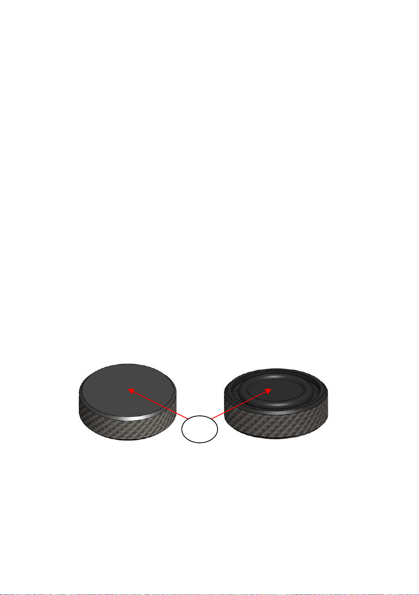
unit. The volatiles cover is a flat circular plate with an O-ring on the
underside for sealing into position when a force is applied from the flat
anvil (17) fitted to the clamp arm assembly (18). (See Figs 15. and 16.)
21
Fig 15. Volatiles Cover (top view left – underside view right)
When a volatile solvent or solution sample has been spotted into
position over the crystal of an ATR crystal puck, the underside of the
volatiles cover (21) is placed over the sample. Rotate the clamp arm
assembly (18) with fitted flat anvil (17) from its parked position towards
Page 37
Quest Single Reflection ATR Accessory
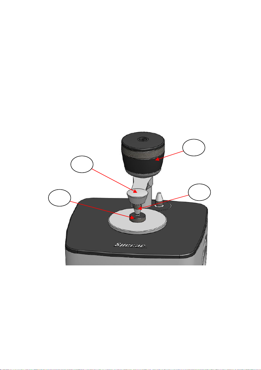
the front of the optical unit, ensuring there is enough clearance of the
anvil pressing surface from the top side of the volatiles cover (21) that
has been placed into position over the crystal. The clamp arm
assembly (18) will click correctly into the sampling position over the
crystal area when turned towards the front. Begin turning the torque
screw knob (20) clockwise to lower the stainless steel flat anvil (17)
towards the volatile cover (21). Continue rotation until the knob “clicks”
with further rotation. At this point the maximum load achievable will be
applied to the volatiles cover to seal its O -ring against the top plate
surface surrounding the ATR crystal and to trap the volatile solvent or
solution sample within.
20
18
21
17
Fig 16. Volatiles Cover clamped into position using the Flat Anvil
with the Clamp Arm Assembly
With the volatiles cover placed into position over the ATR puck
assembly, commence to collect spectral information for the liquid
sample.
35
Page 38
User Manual
36
The Specular Reflectance Puck (P/N GS10816)
The Quest ATR Accessory can be used for the spectral measurement
of solid sample types such as flat surface films by the specular
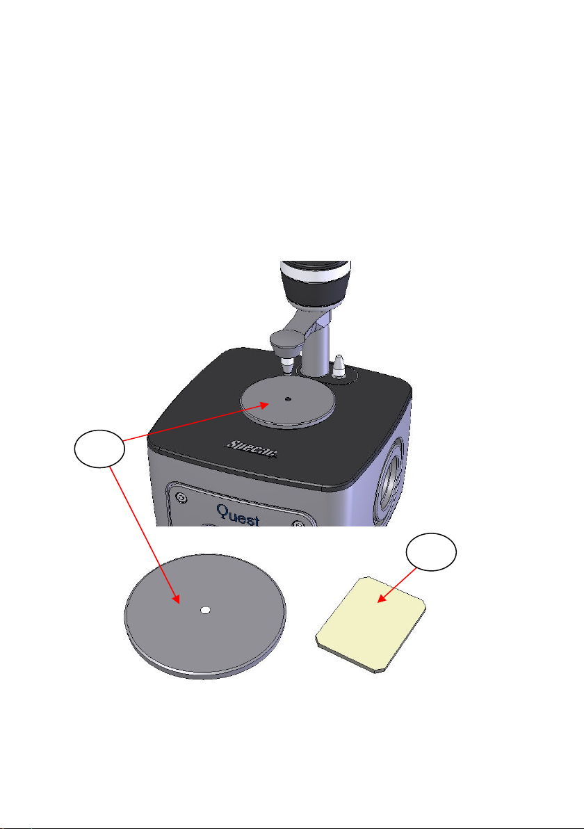
reflectance technique. A crystal puck assembly (22) that has no ATR
crystal fitted is used in place of an ATR crystal puck assembly to
allow the IR light beam passing through the optical unit to be projected
directly to a solid sample surface instead of light passage through an
ATR crystal/sample interface medium.
22
23
Fig 17. Quest Specular Reflectance Puck and Reference Mirror
Page 39

Quest Single Reflection ATR Accessory
As shown at Fig 17, the specular reflectance puck assembly (22) when
installed onto the Quest optical unit presents an open aperture hole of
3.8mm diameter at the central focal point of an incoming beam of IR
light from below. In use, a sample surface to measure is placed face
down over the aperture hole of the puck (22) to allow for a specular
reflectance measurement at a nominal fixed 45° incident angle to be
made. The sample surface must be larger than 3.8mm in diameter to
be supported and to prevent it from falling through the aperture hole.
If necessary, the flat anvil (17) affixed to the clamp arm assembly (18)
could be employed to press against the upper, back surface of any
solid sample type (particularly film samples) to position the sample
more securely and consistently in position for the measurement over
the aperture hole.
Note: This is a similar procedure to the sampling of a solid sample
for contacting against an ATR crystal puck assembly.
A reference mirror (23) is also provided with the specular reflectance
puck (22). In any spectral measurements, the reflective surface of the
mirror (23) is placed face down over the aperture hole to collect a
background reference spectrum to compare and subtract against any
sample spectrum that is made. It’s possible though that an alternative
background reference sample could be used in place of the supplied
reference mirror that is more representative to the actual sample
species to be measured.
Alignment of Optics using the Specular Reflectance Puck
When swapping over from use of a Quest ATR puck assembly to the
specular reflectance puck (or vice versa), it should not be necessary to
realign for the mirror settings in the optical unit. Any alignment of the
mirrors to optimise for a light throughput energy for the Quest ATR
Accessory should be carried out from use of a specific ATR crystal
puck assembly on initial receipt and installation of the accessory.
(Please refer to the alignment procedure on pages 12 to 18 of this
User Instruction Manual.)
37
Page 40

User Manual
38
When the Quest ATR Accessory has been aligned for an optimum
throughput against an ATR crystal puck as fitted to the optical unit, with
a changeover fitting of the specular reflectance puck and use of the
supplied reference mirror, a typical background throughput energy
level is circa 30% for the 45° incident angle of a specular reflectance
measurement as compared to an unobstructed beam from source to
detector.
Notes On Cleaning
When cleaning a diamond, ZnSe, Ge or Si ATR crystal of the Quest
ATR crystal puck assembly in preparation for a new sample, it is very
important to take care to avoid damage to the crystal materials. As
also mentioned in the Safety Considerations (Section 2, page 5), of the
four crystal materials ZnSe is potentially the most hazardous in terms a
toxicity risk from contact with the skin.
Note: Always wear gloves to protect yourself and the
ATR crystal material.
A useful feature of the Quest ATR Accessory is the capability for
removal of the ATR crystal puck from the optical unit, such that any
sample can be prepared remotely and safely, if desired, onto the ATR
crystal surface and then the ATR crystal puck assembly can be bought
for fitting onto the optical unit whilst installed in the spectrometer.
Similarly, for cleaning it may be useful to remove the crystal puck from
the optical unit and carry it to a safe area for solvent cleaning and
wiping with a tissue and therefore minimise any risk of contamination
being carried over to other components of the accessory whilst in situ.
When wiping away any solid or liquid sample, use very soft lens
tissues to avoid scratches being caused on the surface of the ATR
crystal, particularly if using the ZnSe, Ge or Si crystal pucks as
these crystal materials are not as resilient as diamond. Scratches
and blemishes to the ATR crystal surface will result in poor light
throughput for the ATR technique and an overall degradation in the
accessories performance.
Page 41

Quest Single Reflection ATR Accessory
Solvents such as water, methanol and acetone are suitable to use for
cleaning purposes. Sample solutions that fall within the pH range of
pH4 to pH11 are tolerated by the ZnSe crystal material. Stronger acids
and bases will damage ZnSe irreparably.
Note: When cleaning the flat, self-levelling anvil (17), do not soak the
contact tip head with solvent as this degrades the nitrile washer
component. Carefully wipe the stainless steel tip head only using
moistened or dry tissues to clean it.
In common and general usage, it will only be necessary to wipe and
clean away at the top surface of any Quest ATR crystal puck between
samples. If possible, try to avoid any solvent or cleaning solution
materials from getting to the underside of the crystal puck. There is a
risk that any dried solution components that have been introduced to
this underside of the ATR crystal puck could be observed as an
“impurity” against the ATR crystal in any “background” spectrum to be
collected, and so this contaminant would need to be removed before
any further sampling can continue.
Diamond Crystal Considerations
The diamond crystal material in the crystal puck options P/N’s
GS10810, GS10811, GS10826 and GS10827 is much more chemically
durable than either the ZnSe, Ge or Si crystal puck options. Therefore,
if a sample is stubbornly resistant to removal from the crystal surface,
a more “vigorous” method of cleaning may be carried out for the
diamond material than could be achieved with the ZnSe or Ge crystal
puck options. More aggressive solvents and abrasive cleaners could
be considered suitable for use to remove the sample, if these are
necessary.
Warning: A procedure for cleaning away a stubborn sample
from the top surface of a diamond crystal puck assembly,
should it prove to be effective, should never be considered for
use with either the ZnSe or Ge crystal puck options. It is highly
likely these crystal materials themselves will be irreparably
damaged from the cleaning regime.
39
Page 42

User Manual
40
Data Sheet For Diamond
General
Hardest substance known for carbon (C) elemental form.
Can be shaped, cut and polished to form spectral transmission window or
crystal for ATR spectroscopy.
Has a highish Refractive Index value and can suffer reflection losses but these
can be improved with antireflection optical coatings
Extremely chemically resistant to practically all known materials.
Element symbol: C
Chemical Abstracts Service (CAS) No: 7440-44-0 (Synthetic) : 7782-42-5
(Natural)
Physical Data
Appearance: Clear, transparent and generally colourless solid. Has no odour.
Melting point: N/A.
Boiling point: 4827°C.
Vapour pressure: N/A.
Specific gravity: 2.26 g cm-3.
Solubility in water: Insoluble
Hardness: 5700 Kg/mm2.
Refractive Index: 2.43 (at 2000cm-1 - wavenumbers).
Spectroscopic transmission range: 40,000 to 10 cm-1 (wavenumbers).
Stability
Stable.
Toxicology
Not classified as a dangerous or harmful material according to EC directives.
Personal Protection
Always wear safety spectacles and gloves when handling the window or
crystal material.
Allow for adequate ventilation.
Storage
Keep windows or crystal stored in a cool, dry container.
Page 43
Quest Single Reflection ATR Accessory
Data Sheet For Zinc Selenide
General
Toxic and hard, yellow coloured crystalline powder when fused together as a
solid can be used as a transmission window material or as a crystal material
for attenuated total reflectance (ATR) FTIR spectroscopy.
Insoluble in water, but attacked by strong acids and bases. (pH range 4 to 11
tolerant). Organic solvents have no effect.
Fairly brittle as a window material and sensitive to thermal and mechanical
shock.
Molecular formula: ZnSe
Chemical Abstracts Service (CAS) No: 1315-09-9.
Physical Data
Appearance: Yellow crystals, granular powder or amber coloured window
material.
Melting point: 1515°C at 1.8 atmospheres. (26.5psi)
Solubility in water: 0g/100g at 0°C.
Hardness: 120 Kg/mm2.
Refractive Index: 2.43 (at 2000cm-1 - wavenumbers).
Spectroscopic transmission range: 20,000 to 500 cm-1 (wavenumbers).
Stability
Stable. Reacts with acids to give highly toxic hydrogen selenide. May be air
and moisture sensitive. Incompatible with strong acids, strong bases and
strong oxidising agents.
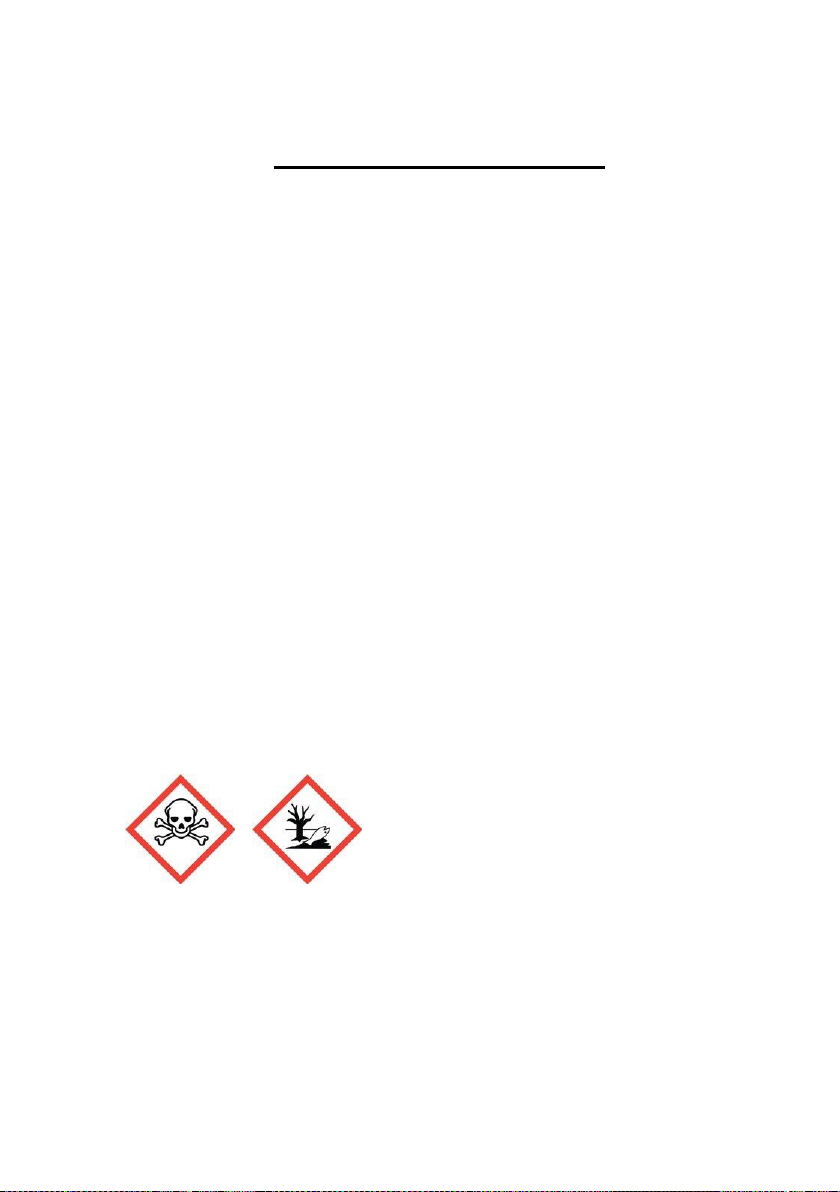
Toxicology
Toxic if small amounts are inhaled or
swallowed. In stomach toxic hydrogen
selenide (H2Se) is liberated. Skin and eye
irritant. Danger of cumulative effects from
frequent handling without protection.
Personal Protection
Always wear safety spectacles and gloves when handling the powder or
window material. Allow for good ventilation.
Storage
Keep powder or windows stored in a cool, dry container, with appropriate
safety labelling.
41
Page 44

User Manual
42
Data Sheet For Germanium
General
Hard and very brittle material, but can be shaped, cut and polished to form
spectral transmission window or crystal for ATR spectroscopy.
Because of its high Refractive Index value suffers from large reflection losses
but these can be improved with antireflection optical coatings
Is temperature sensitive and loses transmission when heated. (Is optically
opaque to IR transmission at 190°C temperature.)
Insoluble in water and alcohols. Soluble in hot sulphuric acid and aqua regia.
Element symbol: Ge
Chemical Abstracts Service (CAS) No: 7440-56-4.
Physical Data
Appearance: Greyish/black, opaque, elemental, metallic solid. Has no odour.
Melting point: 737°C.
Boiling point: 2830°C.
Vapour pressure: 2.66 x 10
Specific gravity: 5.323 g cm-3.
Solubility in water: Insoluble
Hardness: 780 Kg/mm2.
Refractive Index: 4.01 (at 2000cm-1 - wavenumbers).
Spectroscopic transmission range: 5,500 to 500 cm-1 (wavenumbers).
Stability
Stable.
Toxicology
Harmful if ingested in large amounts, if inhaled, or if in repeated
contact with the skin.
Personal Protection
Always wear safety spectacles and gloves when handling the window or
crystal material.
Allow for adequate ventilation.
Storage
Keep windows or crystal stored in a cool, dry container.
-56
mm Hg at 25°C.
Page 45

Quest Single Reflection ATR Accessory
Datasheet for Silicon
General
Synonyms: Defoamer S-10.
When powder is fused together, is used as a transmission window material.
Very hard, but brittle and relatively inert material. Insoluble in water, resists
acids and bases but is attacked by combination of hydrofluoric and nitric acid.
Can withstand thermal shock.
Useful for Far IR working in the region 400 to 33cm-1
Molecular formula: Si.
Chemical Abstracts Service (CAS) No: 7440-21-3
Physical Data
Appearance: Grey lustrous solid or grey powder.
Melting point: 1410°C.
Boiling point: 2355°C.
Solubility in water: 0g/100g at 0°C.
Hardness: 1150 Kg/mm2.
Refractive Index: 3.42 (at 2000cm-1 - wavenumbers).
Spectroscopic transmission range: 8,333 to 33 cm-1 (wavenumbers) - not
continuous as absorptions in the Mid IR from circa 1300 to 500 cm-1.
Stability
Stable.
Fine powder is highly flammable. Incompatible with
oxidizing agents, bases, carbonates, alkali metals, lead
and aluminium oxides, halogens, carbides and formic
acid.
Toxicology
Generally regarded as safe.
Personal Protection
Always wear safety spectacles and gloves when handling the powder or
window material.
Allow for adequate ventilation.
Storage
Keep powder or windows stored in a cool, dry container.
43
Page 46

User Manual
44
9. Quest ATR Accessory “Bubble Numbers”
Part Identification List
(1) Optical unit fixing thumb screw to Benchmark™ baseplate.
(2) Location slot of ATR crystal puck assemblies.
(3) Location pin on top surface of the optical unit.
(4) Magnetic catch for ATR crystal puck assemblies.
(5) Front cover plate of optical unit.
(6) Captive screw of front cover plate.
(7) Grub screw for M6 mirror rotation.
(8) Cap head screw for M6 mirror tilt.
(9) Grub screw for M3 mirror rotation.
(10) Cap head screw for M3 mirror tilt.
(11) Grub screw for M1 mirror rotation.
(12) Cap head screw for M1 mirror tilt.
(13) Purge tube location port in front cover plate.
(14) Curved grip plate for purge tubing in front cover plate.
(15) Purge bellow.
(16) Aperture port on optical unit.
(17) Flat or pellet compression head anvil.
(18) Clamp arm assembly.
(19) Anvil storage port.
(20) Torque screw knob.
(21) Volatiles cover.
(22) Specular reflectance puck.
(23) Reference mirror for specular reflectance puck.
Page 47

Quest Single Reflection ATR Accessory
10. Quest ATR Accessory Spare Parts
Complete Accessories – (Optical unit with clamp arm assembly,
specific ATR crystal puck option and Benchmark™ baseplate)
P/N GS10800-X Quest ATR Diamond Accessory.
P/N GS10801-X Quest ATR Diamond Extended Range Accessory.
P/N GS10802-X Quest ATR ZnSe Accessory.
P/N GS10803-X Quest ATR Ge Accessory.
P/N GS10804-X Quest ATR Si Accessory
P/N GS10806-X Quest ATR Diamond Accessory (DLC Coated).
P/N GS10807-X Quest ATR Diamond Extended Range Accessory
(DLC Coated).
Note: To purchase a Quest ATR Accessory with a specific coloured
top surface, specify the appropriate letter for colour coding in
place of ‘X ’after the part number when ordering. (See page 4.
e.g. GS10800-R for Quest ATR Diamond Accessory (Red)).
Replacement Crystal Puck Assemblies
P/N GS10810 Quest ATR Diamond Crystal Puck.
P/N GS10811 Quest ATR Diamond Extended Range Crystal Puck.
P/N GS10812 Quest ATR ZnSe Crystal Puck.
P/N GS10813 Quest ATR Ge Crystal Puck.
P/N GS10819 Quest ATR Si Crystal Puck.
P/N GS10826 Quest ATR Diamond Crystal Puck DLC Coated.
P/N GS10827 Quest ATR Diamond Extended Range Crystal Puck
DLC Coated.
Spare Parts
P/N GS10816 Quest Specular Reflectance Puck.
P/N GS10820 Quest ATR Self Levelling Flat Anvil.
P/N GS10821 Quest ATR Pellet Anvil.
P/N GS10825 Quest ATR Volatiles Cover.
P/N GS10707 Purge Bellows (pair).
45
Page 48

User Manual
46
ZnSe
Ge
Diamond
Si
Active Area
Anvil
Travel
Weight
W x D X H (mm)
11. Quest ATR Technical Specifications
ATR Crystal
Accessory
Transmission
Range cm-1
Refractive Index
at 1000cm-1
Depth of
Penetration
ATR Crystal
Plate Assembly
Applied Force
From Clamp
ZnSe 45°
3.4 mm dia.
7,800 - 500
(AR coated)
2.43
2.0µm
(For Sample
of Refractive
index 1.5 @
1000cm-1)
ZnSe sealed
with Indium
into
hardened
stainless
steel
top plate
40 lbs
Ge 45°
3.4 mm dia.
5,500 - 480
(AR coated)
4.0
0.7µm
(For Sample
of Refractive
index 1.5 @
1000cm-1)
Ge sealed
with Indium
into
hardened
stainless
steel
top plate
40 lbs
Diamond 45°
1.8 mm dia.
7,800 - 400
(AR coated)
10,000 - 40
(Extended)
2.40
2.0µm
(For Sample
of Refractive
index 1.5 @
1000cm-1)
Diamond
sealed with
Indium into
hardened
stainless
steel
top plate
40 lbs
Si 45°
3.4mm dia
8,000 – 100
(absorbs
between
1300 – 500)
3.42
0.9µm
(For Sample
of Refractive
index 1.5 @
1000cm-1)
Si sealed
with Indium
into
hardened
stainless
steel
top plate
40 lbs
Maximum
Compression
Head (Anvil)
Quest ATR
Accessory
Quest ATR
Dimensions
18mm
1.6Kgs
150 x 150 x
180
18mm
1.6Kgs
150 x 150 x
180
18mm
1.6Kgs
150 x 150 x
180
18mm
1.6Kgs
150 x 150 x
180
Page 49

Quest Single Reflection ATR Accessory
an
d Description
Number
12. Quest ATR Serial Numbers
Your Quest ATR Accessory will be provided with a serial number for
identification of certain individual part assemblies. To help you, please
use the grid below to fill in the serial number information of the Quest
ATR Accessory parts you have received. If you need to contact
Specac for any issues regarding your Quest ATR Accessory, it may be
necessary to provide the serial number of the item to identify for
replacement parts.
Quest ATR Part Number
Serial
P/N GS10800 – optical unit with clamp arm assembly and
diamond (AR coated) top plate assembly
P/N GS10801 – optical unit with clamp arm assembly and
diamond (extended range) top plate assembly
P/N GS10802 – optical unit with clamp arm assembly and
ZnSe (AR coated) top plate assembly
P/N GS10803 – optical unit with clamp arm assembly and
Ge (AR coated) top plate assembly
P/N GS10804 – optical unit with clamp arm assembly and Si
(non-AR coated) top plate assembly
P/N GS10806 – optical unit with clamp arm assembly and
diamond (AR coated) DLC top plate assembly
P/N GS10807 – optical unit with clamp arm assembly and
diamond (extended range) DLC top plate assembly
P/N GS10810 – Diamond (AR coated) puck
P/N GS10811 – Diamond (extended range) puck
P/N GS10812 – ZnSe (AR coated) puck
47
Page 50

User Manual
48
P/N GS10813 – Ge (AR coated) puck
P/N GS10819 – Si (non-AR coated) puck
P/N GS10826 – Diamond (AR coated) puck DLC
P/N GS10827 – Diamond (extended range) puck DLC
Page 51

Worldwide Distribution
France
Eurolabo - Paris.
Tel.01 42 08 01 28
Fax 01 42 08 13 65
email: [email protected]
Germany
L.O.T. - Oriel GmbH & Co,
KG - Darmstadt
Tel: 06151 88060
Fax: 06151 880689
email:[email protected]
Website: www.LOT-Oriel.com/de
Japan
Systems Engineering Inc. -Tokyo
Tel: 03 3946 4993
Fax: 03 3946 4983
email:[email protected]
Website: www.systems-eng.co.jp
Spain
Teknokroma S.Coop C. Ltda
Barcelona
Tel: 93 674 8800
Fax: 93 675 2405
email: [email protected]
Switzerland
Portmann InstrumentsAG
Biel-Benken
Tel: 061 726 6555
Fax: 061 726 6550
email: [email protected]
Website:www.portmann-instruments.ch
USA
SPECAC INC.
414 Commerce Drive
Suite 175,
Fort Washington,
PA 19034, USA
Tel: 215 793 4044
Fax: 215 793 4011
United Kingdom
Specac Ltd. - London
River House, 97 Cray Avenue,
Orpington
Kent BR5 4HE
Tel: +44 (0) 1689 873134
Fax: +44 (0) 1689 878527
Registered No. 1008689 England
Page 52

Brilliant Spectroscopy™
SPECAC INC.
414 Commerce Drive
Suite 175,
Fort Washington,
PA 19034, USA
Tel: 215 793 4044
Fax: 215 793 4011
www.specac.com
River House, 97 Cray Avenue,
Registered No. 1008689 England
SPECAC LTD.
Orpington
Kent BR5 4HE
Tel: +44 (0) 1689 873134
Fax: +44 (0) 1689 878527
 Loading...