

Page 1
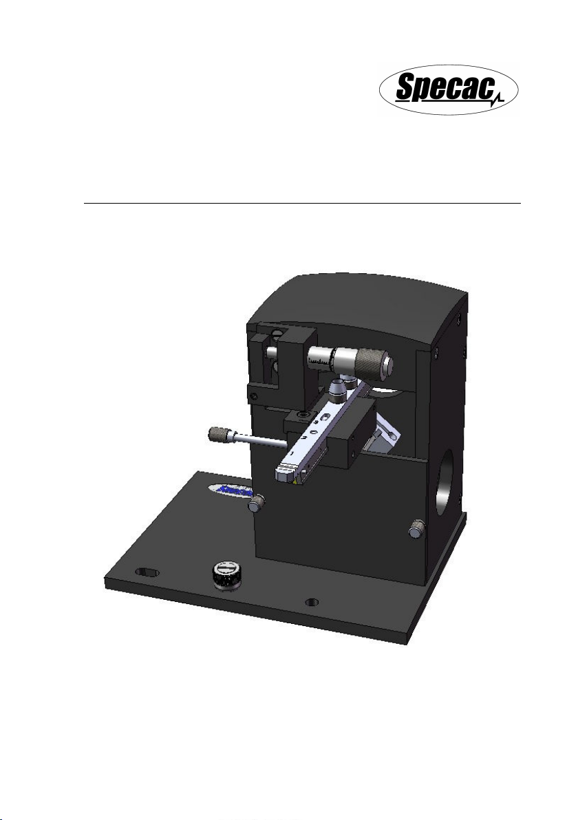
Minidiff Plus
Diffuse Reflectance Accessory
User Manual
2I-04510-4
Page 2

Page 3

Minidiff Plus
Diffuse Reflectance Accessory
User Manual
2I-04510-4
Page 4

User Manual
Minidiff Plus Diffuse Reflectance Accessory
P/N GS04510
CONTENTS
1.
INTRODUCTION
2.
SAFETY CONSIDERATIONS
3.
CHECKLIST OF CONTENTS
4.
INSTALLATION USING BENCHMARK™ BASEPLATE
5.
ALIGNMENT PROCEDURE FOR THE MINIDIFF PLUS DIFFUSE
REFLECTANCE ACCESSORY
SAMPLE CUPS FOR THE MINIDIFF PLUS ACCESSORY
FILLING A SAMPLE CUP WITH POWDER SAMPLE
LOADING A SAMPLE CUP INTO THE SAMPLING POSITION
ALIGNMENT PROCEDURE
6.
OPTICAL BEAM PATHLENGTH OF THE MINIDIFF PLUS AND MIRROR
ALIGNMENT
REALIGNMENT OF THE ADJUSTABLE MIRROR ASSEMBLY
ADJUSTABLE MIRROR ALIGNMENT PROCEDURE
7.
SAMPLING WITH THE MINIDIFF PLUS ACCESSORY
SAMPLE CUP OR DIABRAZE PAD FOR USE
PROCEDURE FOR MEASUREMENT WITH THE SAMPLE CUP
COLLECTING A BACKGROUND SPECTRUM
COLLECTING A SAMPLE SPECTRUM
PROCEDURE FOR MEASUREMENT WITH THE DIABRAZE PAD
COLLECTING A BACKGROUND SPECTRUM
COLLECTING A SAMPLE SPECTRUM
8.
CLEANING THE MINIDIFF PLUS AFTER USE
9.
MINIDIFF PLUS ACCESSORY "BUBBLE NUMBERS" PART IDENTIFICATION
LIST
............................................................................................... 30
10.
MINIDIFF PLUS ACCESSORY SPARE PARTS
11.
MINIDIFF PLUS SERIAL NUMBERING
© February 2016 Specac Ltd. All rights reserved.
Benchmark and Brilliant Spectroscopy are trademarks of Specac Ltd.
Other product names mentioned herein may be trademarks
................................................................................. 3
................................................................. 5
.................................................................. 6
.............................. 10
............................................................ 12
........................... 13
.................................. 13
..................... 15
................................................................. 16
..................................................................................... 19
..................... 19
................................. 21
............................... 24
.......................................... 24
.................. 26
.......................................... 26
................................................... 26
................ 27
.......................................... 27
................................................... 27
......................................... 29
....................................... 31
................................................. 32
of their respective owners.
2
Page 5

Minidiff Plus Diffuse Reflectance Accessory
1. Introduction
Thank you for buying a Specac product. We trust it will provide you
with invaluable and excellent service in use.
Infrared radiant light when reflected from a solid surface can be either
diffusely or specularly scattered (or both - total reflectance) in nature.
Diffuse reflectance is based upon the collection of radiation that has
been diffusely scattered from the sample. From illumination by
infrared radiation of a solid sample surface that can be deemed nonlinear or irregular (e.g. powdered, granular or fabric/textile type
samples), although there will be components of some specularly
reflected light from the surface, the majority of light to collect for a
measurement will be diffusely scattered.
The diffuse reflectance technique has been used routinely for many
years to analyse such sample types from collection of an Infrared
spectrum. This has been achieved because of the relative simplicity of
the sampling technique and the low cost of diffuse reflectance
accessories for use within an Infrared spectrometer.
The Minidiff Plus P/N GS04510 is a versatile high performance diffuse
reflectance accessory from Specac. It has an “on-axis” design for the
optical IR beam pathway of analysis light from source to sample to
detector and collects for a total reflectance of light. (Both diffuse and
specular reflected light components.) This allows for a high level
energy throughput of IR light to be measureable when the Minidiff Plus
has been installed correctly into the sample compartment of many
commercially available IR spectrometer systems.
For a correct fitting of the Minidiff Plus into the spectrometer it is
mounted on an appropriate Benchmark™ baseplate that matches the
spectrometer system. Baseplate mounting provides for added stability
of the accessory in use and consistent reproducibility for any sampling
measurements.
3
Page 6
User Manual
Minidiff Plus Diffuse Reflectance Accessory
4
Page 7

Minidiff Plus Diffuse Reflectance Accessory
2. Safety Considerations
With use of any spectroscopic accessory that involves the study of a
wide range of chemical samples, the associated risk in operation may
mostly be attributed to the specific sample type to be handled itself. As
far as it is possible you should follow a procedure for safe handling and
containment of the type of sample to be used.
With respect to safety of use specifically for the Minidiff Plus diffuse
reflectance accessory, the main risk is from the potential contact with
any sample type that may be injurious to health when exposed to the
local environment. An appropriate sample type for a Minidiff Plus
diffuse reflectance measurement is contained in an open sampling cup
or transferred to an abrasive pad surface for direct measurement of the
sample from an analysis beam of light projected to the exposed
surface.
Important:
The general rule when working with any chemical
materials is to always wear protective clothing,
specifically gloves and safety spectacles when handling,
to obviate the risk of contact with the skin.
If possible, always keep any sampling time to a minimum for exposure
of a chemical substance and store the sample safely away as soon as
possible, or where necessary, after analysis.
The same considerations for safety in handling of the Minidiff Plus
diffuse reflectance accessory should be observed when the equipment
is being cleaned and cared for between sampling.
5
Page 8
User Manual
3. Checklist of Contents
The Minidiff Plus diffuse reflectance accessory P/N GS04510 is
provided as packed in a carry case. Open up the carry case and
carefully remove the items within for checking and inspection. On
receipt of the accessory please check that the following have been
supplied:
•
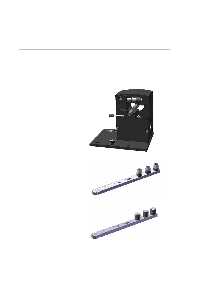
Minidiff Plus optical unit.
•
One 3-position sample cup
holder mount assemblies
(with 1 fixed sample cup
on each and 4 spare
sample cups).
•
One 3-position abrasive
sample pad mount
assemblies (with 1 fixed
abrasive sample pad
mount on each and 4
spare pad mounts).
6
Page 9
Minidiff Plus Diffuse Reflectance Accessory
•
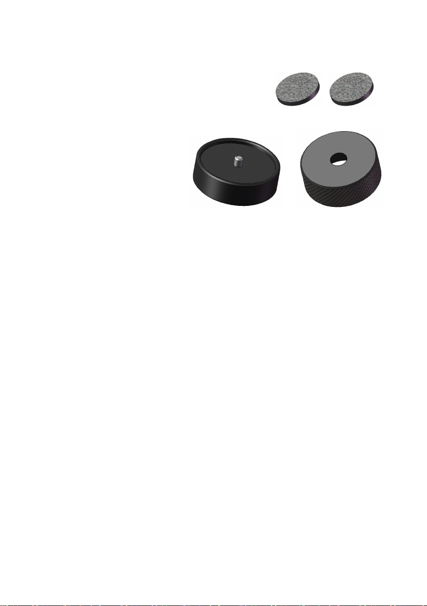
20 Diabrase sample pads (for abrasive
pad mounts).
•
Sample filler parts.
•
Spectroscopic grade KBr powder (50g).
•
Pestle and Mortar.
•
Spatula.
•
Benchmark™ baseplate ordered with Minidiff Plus for installation
into a specific spectrometer.
•
Set of Allen keys – 1.5mm A/F, and 2.5 mm A/F.
•
User Instruction Manual for the Minidiff Plus.
•
Benchmark™ baseplate User Installation Manual.
Note! The Minidiff Plus is factory aligned before despatch and care
should be taken when unpacking not to disturb the two flat
mirrors or micrometer screw. The mirrors can be misaligned by
careless handling or from any excessive force.
Before use, protective tissue covers need to be removed from the
internal flat mirrors within the Minidiff Plus accessory. To gain access
for the protective covers removal, please carry out the following
sequence.
1. Carefully lift the Minidiff Plus optical unit out of the carry case from
the base support plate and the sides of the accessory.
7
Page 10
User Manual
2
1
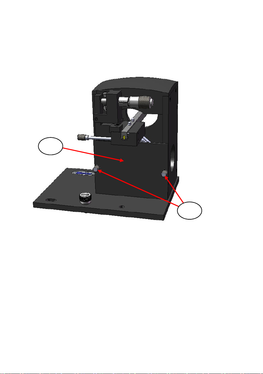
2. Loosen the two front metal cover plate thumbscrews (1) by turning
them anticlockwise and remove the front metal cover plate (2) to
gain access to the internal flat mirror optics. (See Fig 1.)
Fig 1. Front Metal Cover Plate of Minidiff Plus Optical Unit
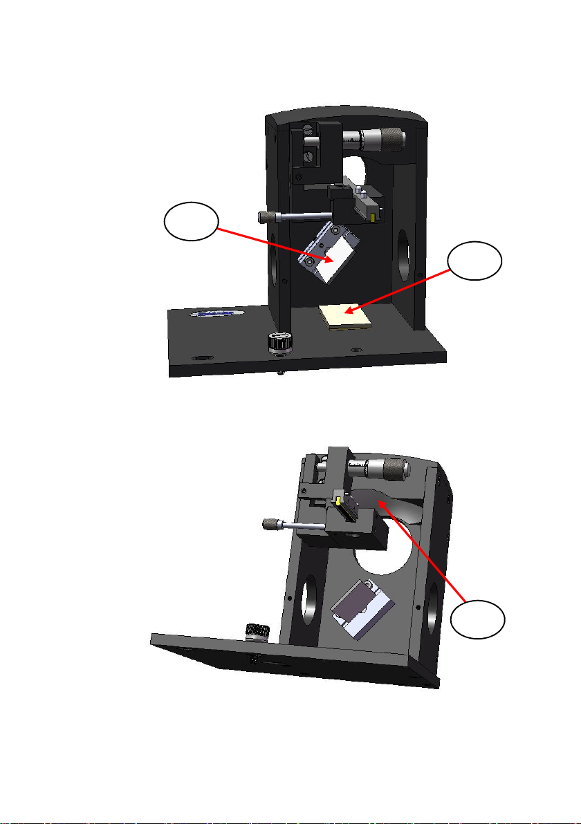
3. Remove all the protective covers from the flat mirrors (3) and (4)
and check the ellipsoid mirror (5). (See Fig 2. and Fig 3).
4. With the protective mirror covers removed, replace the front metal
cover plate (2) and tighten (turn clockwise) the front metal cover
plate thumbscrews (1) to re-secure.
8
Page 11
Minidiff Plus Diffuse Reflectance Accessory
3
4
5
Fig 2. Minidiff Plus Flat Mirror Assemblies Below Sample Position
Fig 3. Minidiff Plus Ellipsoid Mirror Above Sample Position
9
Page 12
User Manual
10
7
6
4. Installation Using Benchmark™ Baseplate
The Minidiff Plus accessory is Benchmark™ baseplate mounted for a
correct installation and positioning within the sample compartment of
the IR spectrometer system. Initially, any spectrometers own 3” x 2”
slide sample mount will normally have to be removed before the
Minidiff Plus accessory on the Benchmark™ baseplate can be
installed.
Note: It is best to install the Benchmark™ baseplate in the
spectrometer first before fixing the Minidiff Plus into position.
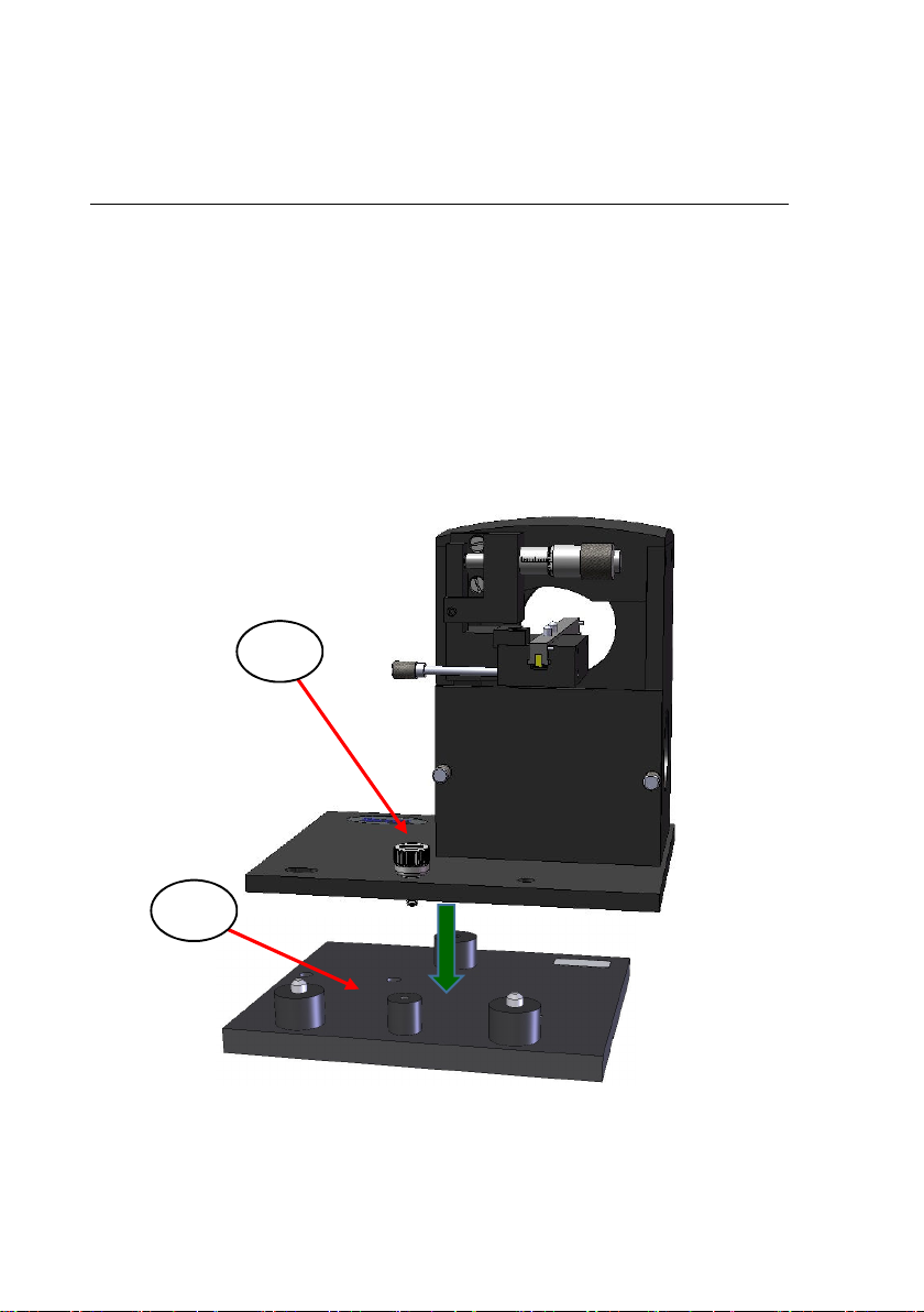
Fig 4.
Minidiff Plus Accessory Fitted to a Benchmark™ Baseplate
Page 13

Minidiff Plus Diffuse Reflectance Accessory
The Benchmark™ baseplate (6) typically has three support pillars (one
flat support pillar towards the rear and two at the front with location
pins) and a fourth front central pillar into which the fixing thumb screw
(7) of the Minidiff Plus is tightened.
Fixing holes and studs in the Benchmark™ baseplate (6) will vary
depending upon the make and model of the spectrometer into which
the Minidiff Plus accessory is to be installed. For details on how to
install the Benchmark™ baseplate in the spectrometer, refer to the
Benchmark™ Baseplate User Installation Manual guide supplied.
When the Benchmark™ baseplate (6) has been installed, carefully
align the Minidiff Plus accessory over the Benchmark™ baseplate and
secure it in position by a simultaneous pushing down and clockwise
rotation of the fixing thumbscrew (7) into the Benchmark™ baseplates
(6) front central location pillar. (See Fig 4.)
Removal of the Minidiff Plus away from the Benchmark™ baseplate (6)
is a reverse action in anticlockwise rotation for loosening of the fixing
thumbscrew (7) and separation of the parts.
11
Page 14
User Manual
12
9
8
5. Alignment Procedure for the Minidiff Plus
Diffuse Reflectance Accessory
When the Minidiff Plus accessory has been installed into the
spectrometer correctly on a Benchmark™ baseplate (6), there will be a
need to optimize for the IR beam energy throughput of the accessory
from an alignment procedure. The alignment procedure involves an
adjustment to the focal point position of an incoming IR analysis
beam from the overhead ellipsoid mirror (5) towards the sample
surface prior to any diffuse or specular reflectance scatter of light from
the sample.
Note: Any Minidiff Plus will be supplied from Specac already
preliminarily aligned to give an energy throughput reading when
initially installed into the spectrometer sample compartment. It is
necessary to finely adjust the sample surface focal position for
optimisation of a throughput energy level specifically for an
installation into any new spectrometer system.
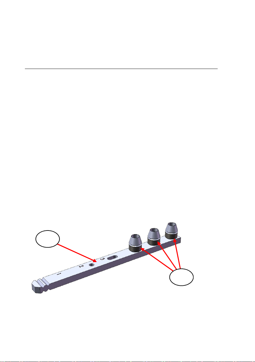
To align for the sample surface focal point position, one of the sample
cups (8) is used in the sampling position with the Minidiff Plus
sample cup mount holder assembly (9). (See Fig 5.)
Fig 5. Minidiff Plus Sample Cups on Mount Holder Assembly
Page 15
Minidiff Plus Diffuse Reflectance Accessory
9
8
Sample Cups for the Minidiff Plus Accessory
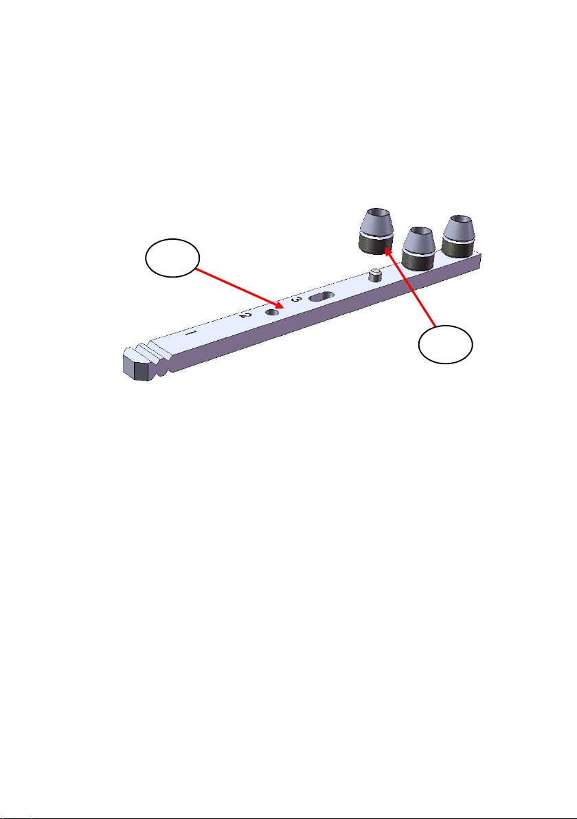
A sample cup (8) is 5mm diameter and 3mm deep for powder sample
containment. It simply push fits over a location pin on the mount holder
assembly (9) for its particular sampling position. (See Fig 6.)
Fig 6. Fitting of Sample Cup to the Mount Holder Assembly
Figs 5 and 6 show three sample cups (8) fitted to the mount holder
assembly (9). The positions of the cups as shown from left to right
correspond to the loaded sampling positions 1, 2 or 3 as marked on
the mount holder assembly (9).
Note: The sample cup (8) that is already affixed to the sample cup
mount holder assembly (9) at sampling position 3 can be used
for the alignment procedure if preferred.
Filling a Sample Cup with Powder Sample
Any sample cup (8) affixed to the mount holder assembly (9) can be
used for the alignment procedure and is filled with dry, finely ground
Potassium Bromide (KBr) or Potassium Iodide (KI) powder, to make a
diffuse reflectance sample measurement for optimization of the light
beam pathway and throughput from the Minidiff Plus accessory.
13
Page 16
User Manual
14
10
8 11
It may be more convenient and easier to use the sample filler parts
(10) and (11) supplied to correctly fill the sample cup (8) with KBr or KI
powder, prior to the fitting of the sample cup (8) to the mount holder
assembly (9), if the fixed sample cup (8) at sampling position 3 is not
wished to be used.
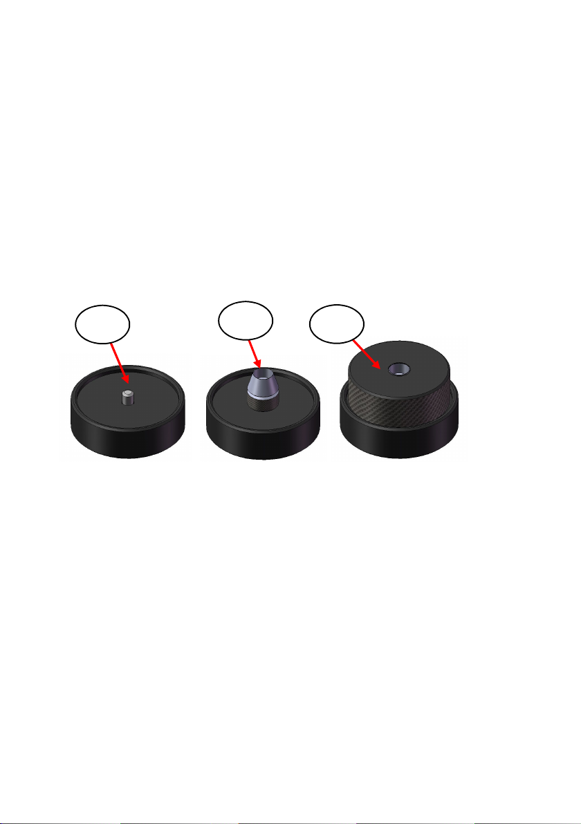
The sequence for filling a sample cup (8) is as follows. Take the
sample filler base (10) and place it on a flat surface. Position an empty
sample cup (8) over the central location pin of the sample filler base
(10). Now position the sample filler cap (11) over the base (10) with
cup (8), such that the top edge of the cup (8) is flush level with the top
surface of the cap (11). (See Fig 7.)
Fig 7. Sample Cup Filling Sequence Using Sample Filler Parts
Fill the sample cup (8) with KBr or KI powder, and gently flatten down
the powder surface with a flat piece of glass or polished metal, so that
it is level with the top of the sample cup (8) and filler cap (11). Any
excess powder sample will be spread over the surface of the filler cap
(11).
Now, carefully remove the filler cap (11) away from the cup (8) and
base (10) to remove the excess powder sample, leaving a flat, level
surface for the sample in the sample cup (8). Then carefully remove
the filled sample cup (8) away from the base (10).
Carefully place the filled sample cup (8) onto pin location position 1 or
2 on the mount holder assembly (9).
Page 17
Minidiff Plus Diffuse Reflectance Accessory
14
13
9
12 8 15
Should any further powder sample be accidently spilt from the sample
cup (8) when transferring to the mount holder assembly (9), use a soft
brush or tissue to remove away from the sample cup mount holder
assembly (9). Any loose powder outside of the sample cup (8) may fall
onto the lower adjustable (3) and base flat (4) mirror assemblies during
sampling or when the sample cup mount holder (9) is being loaded into
the sampling position.
Loading a Sample Cup into the Sampling Position
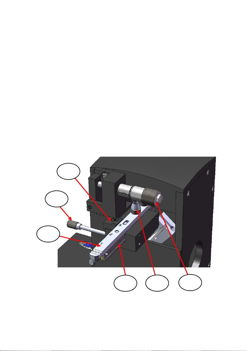
When a sample cup (8) has been filled with powder sample, the
complete cup and mount holder assembly (9) is placed onto the sliding
support rod (12) of the Minidiff Plus accessory for loading into the
sampling position.
Fig 8. Minidiff Plus Sampling Position Indication
15
Page 18

User Manual
16
To place the mount holder assembly (9) onto the sliding support rod
(12), first wind out the support rod (12) by clockwise rotation of the
sample positioning screw (13), until the support rod (12) comes to its
end stop position. Very carefully place to rest the mount holder
assembly (9) into position over the two locating studs of the support
rod (12) as shown at Fig 8, with the sample cups (8) end of the mount
holder assembly (9) nearest towards the Minidiff Plus optical unit.
Rotate the sample positioning screw (13) anti-clockwise, to position the
filled sample cup (8) directly and centrally beneath the ellipsoid mirror
(5) for its sampling position.
A “click” sound will be heard when a particular sampling position for
cup position 1, 2 or 3 has been set. The mount holder assembly (9)
has three sample cup (8) positions to allow for up to three sample cups
(8) to be filled and placed on the support rod (10) at any one time. An
appropriate sampling position to be set for the specific sample cup
(8) position on the mount holder (9) is indicated by the number 1, 2 or
3 as this number aligns with the engraved mark (14) from rotation of
the sample positioning screw (13). (From Fig 8, the sampling
position for the fixed sample cup (8) at position 3 has been set as
shown.)
Note: If any accidental spillage of powder onto the mirrors (3) and (4)
below happens from selecting a sampling position, this should
be removed carefully with a soft brush or tissue at this stage.
The front metal cover plate (2) may need to be removed to gain
access for cleaning,
Alignment Procedure
Note: The Minidiff Plus will be pre-aligned before despatch from
Specac and will only require minor adjustments for the sample
surface focal point position to maximize for a throughput energy
using the test powder sample.
With introduction of a filled sample cup (8) into the sampling position,
at this stage some throughput energy should be registered on the
spectrometer. To measure, the spectrometer display can be set to
Page 19
Minidiff Plus Diffuse Reflectance Accessory
15
16
9
12
register an energy throughput level or signal strength for the
spectrometers system. It is a requirement to know what a typical
energy level is for the spectrometers system that corresponds to a
100% transmission throughput of light when there is nothing in the
beam path of the IR light from the source to the detector of the
spectrometer. This known typical energy throughput value is used to
compare to an energy throughput level attained from a good alignment
of the Minidiff Plus accessory on the particular spectrometer system
into which it has been installed and is to be used.
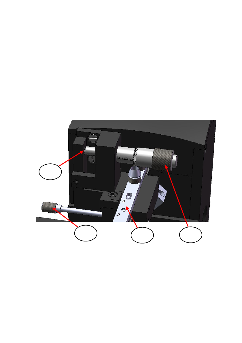
Fig 9. Minidiff Plus Micrometer Adjustment Screw Mechanism
To maximize the energy throughput of the Minidiff Plus accessory,
gently turn the micrometer adjustment screw (15) clockwise or anticlockwise to adjust for the IR beam focal point position for the sample
surface, as contained and filled in the sample cup (8). The “L” shaped
pivot bracket and support table assembly for the sliding support rod
(12) is attached to the micrometer adjustment screw tip with a magnet
17
Page 20

User Manual
18
(16) to ensure that this adjustment operates correctly. The micrometer
adjustment screw (15) tip is always in contact with the magnet (16) in
the pivot assembly such that if rotation of the micrometer screw (15) in
one direction decreases the energy throughput level being seen, then
rotation of the micrometer screw (15) in the opposite direction is
required until an energy maximum has been established.
When correctly aligned an energy signal of between 10-20%
throughput value for KBr or KI sample powder as compared to the
100% value of an unobstructed beam energy throughput should be
obtained on most spectrometers.
Page 21

Minidiff Plus Diffuse Reflectance Accessory
6. Optical Beam Pathway of the Minidiff Plus
and Mirror Alignment
Having installed the MInidiff Plus accessory and followed the alignment
procedure from Section 5) of this User Instruction Manual, the Minidiff
Plus accessory is ready to use for sampling of a wide variety of
solid/powder sample types.
It is usually not necessary to make any further adjustments to the
optical components of the Minidiff Plus accessory to achieve a good
throughput energy level of operation, but there may be an occasion
whereby the adjustable mirror assembly (3) needs to be repositioned
to achieve an optimum throughput from this mirror assembly (3)
realignment. (e.g. the mirror assembly (3) might have been
accidentally moved out of the factory alignment position when the
protective mirror covers were removed from the unpacking and
checking stage.)
Realignment of the Adjustable Mirror Assembly (3)
If the adjustable mirror assembly (3) has moved out of alignment the
following procedure and instructions can be followed to help in a realignment.
Important! If needing to replace any damaged mirror (3) or (4)
components with new parts, or to realign the mirror
assembly (3), take care not to handle or touch the mirror
surfaces.
The optical components of the Minidiff Plus accessory consists of two
flat mirror assemblies (3) and (4), below the sampling position level
and one large ellipsoid (domed) mirror (5) that covers completely over
and above the sampling position level. The optical beam path from
source to sample and to detector for the Minidiff Plus accessory is
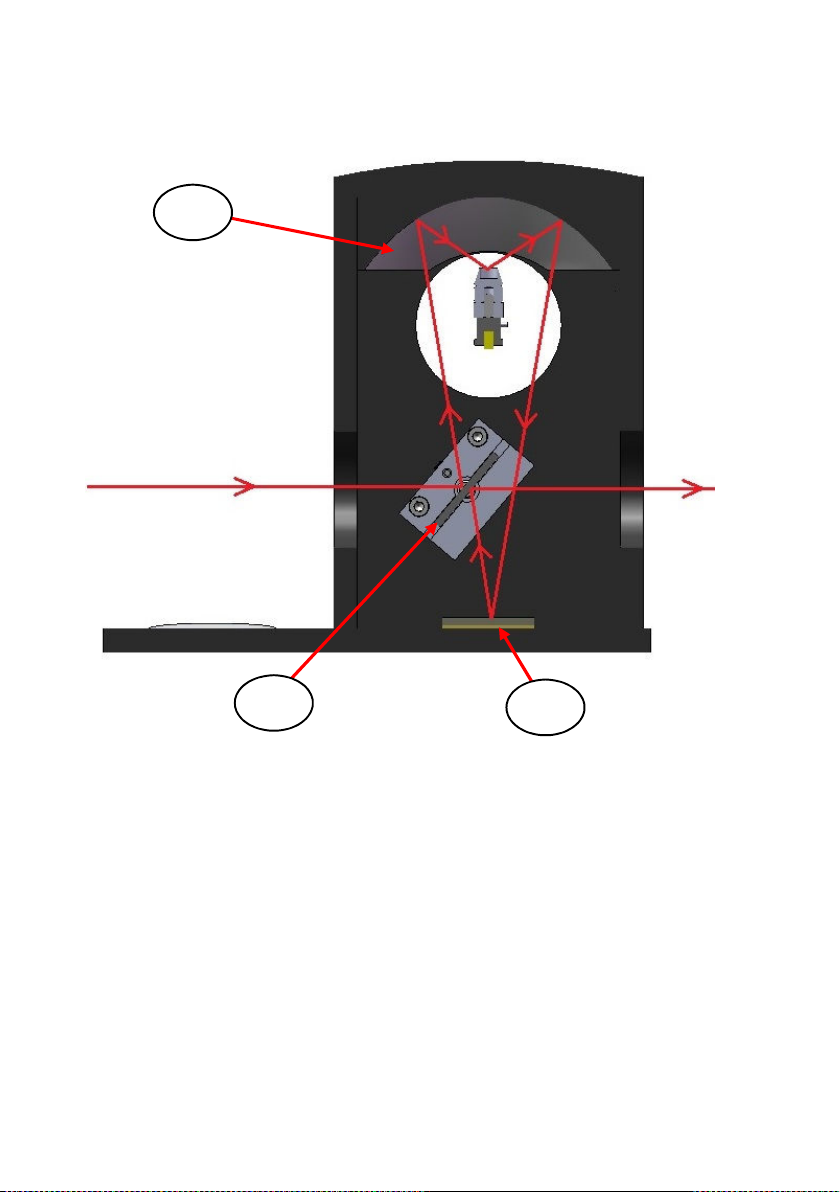
shown in Fig 10.
19
Page 22
User Manual
20
5
3
4
Fig 10. Beam Pathway Schematic for the Minidiff Plus
Diffuse Reflectance Accessory
Fig 10 shows a front cutaway, cross section view of the Minidiff Plus
accessory. The mirror assembly (3) consists of a double sided mirror
(17) on an adjustable mount (18). The mirror (4) is a single sided flat
mirror affixed to the base of the Minidiff Plus accessory and cannot be
adjusted. Similarly, the ellipsoid mirror (5) is also fixed in position at the
top of the Minidiff Plus accessory and cannot be adjusted.
A light beam from a source on the left side of a spectrometer system
and traversing parallel for the beam height of the instrument strikes the
Page 23

Minidiff Plus Diffuse Reflectance Accessory
top surface of the double sided mirror (17) of the mirror assembly (3).
From the angle setting of the mirror assembly (3), the light beam is
reflected up towards the left side half dome of the ellipsoid mirror (5)
and is then directed down towards the sample cup (8) surface level for
its sampling position. Any diffusely or specularly reflected
components of light from the sample surface are collected by the right
side half dome of the ellipsoid mirror (5) and are reflected downwards
to the flat mirror assembly surface (4) at the base of the optical unit.
The light beam is then reflected from mirror (4) to the underside
surface of the double mirror (17) on mirror assembly (3), for a final
reflection towards the right side and the detector of the spectrometer
system.
Note: The beam path for the Minidiff Plus has been shown for a left to
right beam direction passage from source to sample to detector
through the sample compartment of a spectrometer. For a
system that has a right to left beam direction from source to
detector, the performance of the Minidiff Plus is unaffected.
Adjustable Mirror Assembly (3) Alignment Procedure
If the mirror assembly (3) needs to be realigned, carry out the following
procedure.
Take a KBr or KI powder sample for use and follow the procedure for
sampling position alignment as described in Section 5), pages 12 to
18 of this User Instruction Manual.
When the filled sample cup (8) is in its loaded sampling position, (the
numbers 1, 2 or 3 are by the alignment mark (14) for the appropriate
cup position), loosen the two front metal cover plate thumbscrews (1)
and remove the front metal cover plate (2) to gain access to the lower
mirror (3) and (4) assemblies.
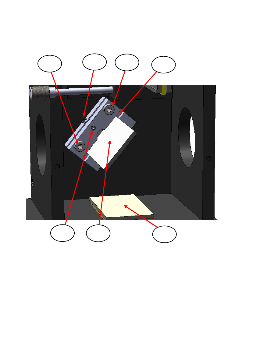
Fig 11 shows a detailed close up of the mirror assembly (3) when the
front metal cover plate (2) has been removed.
21
Page 24
User Manual
22
19
20
19
18
21 17
4
Fig 11. Minidiff Plus Adjustable Mirror Assembly Detail
Using the 2.5mm Allen key supplied, loosen the two cap head screws
(19) in the mirror mount (18) of the mirror assembly (3). The cap head
screws (19) lock the mirror mount (18) into position for the entire mirror
assembly (3) when set at the correct angle for alignment.
Take the 1.5mm Allen key and loosen the locking grub screw (20) to
allow the mirror mount (18) to be gently rotated about its fixing screw
Page 25

Minidiff Plus Diffuse Reflectance Accessory
support shaft.
loosened grub screw (20) to act as a turning lever and gently rotate
the mirror mount (18) clockwise or anti-clockwise until a maximum
energy throughput reading is obtained at the detector of the
spectrometer.
When an optimum throughput energy has been established from a
rotation of the double sided mirror (17), retighten the grub screw (20) to
prevent further rotation of the mirror mount (18) to occur.
The double sided mirror (17) may also need to be tilted for its angle
setting to optimize the throughput energy. To adjust the double sided
mirror (17) tilt position insert the 1.5mm Allen key into the grub screw
(21) and turn it similarly clockwise or anti clockwise to maximize the
energy.
Note: Always complete a rotation movement for a throughput energy
maximum setting before stepping to a tilt movement for any
adjustment in setting (or vice versa).
Now, re-adjust the sampling position surface level by turning the
micrometer screw (15) clockwise or anti-clockwise to maximize the
energy.
It may be necessary to repeat the rotate, tilt and sampling position
adjustment steps a second time until the maximum energy throughput
has been achieved.
When the mirror assembly (3) setting has been established to achieve
an optimum energy throughput, carefully tighten the cap head screws
(19) to lock the double sided mirror (17) on its mount (18) into position
for the new angle setting.
Replace the front metal cover plate (2) and tighten the front metal
cover plate thumbscrews (1) to re-secure.
Use the 1.5mm Allen key whilst it is located in the
23
Page 26
User Manual
24
22
23
7. Sampling With The Minidiff Plus Diffuse
Reflectance Accessory
Sample Cup or Diabraze Pad for Use
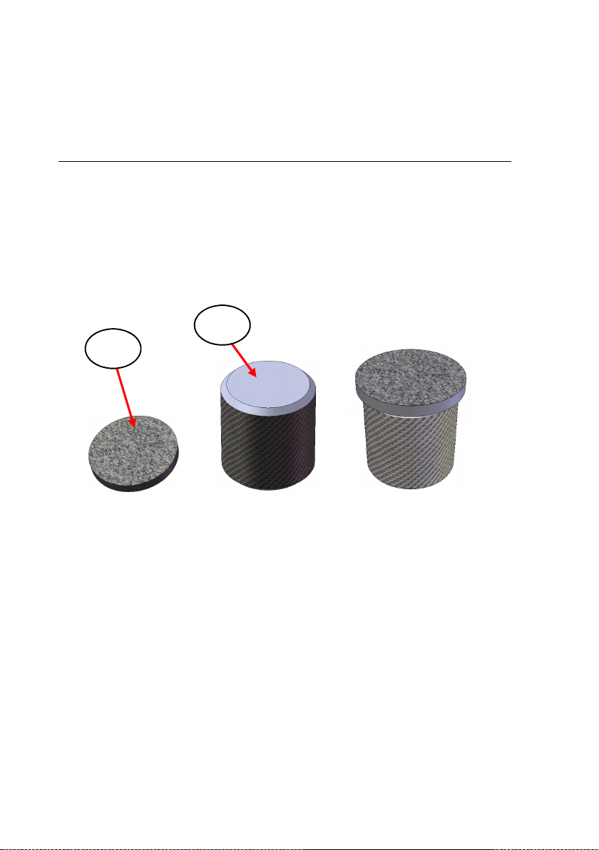
To sample with the Minidiff Plus diffuse reflectance accessory there is
a choice in use of a sample cup (8) for powder solid sampling (See
Fig 5.), or a diabraze pad surface (22) that is affixed to its own mount
(23). (See Fig 12.)
Pad Mount Pad on Mount
Fig 12. Minidiff Plus Diabraze Pad and Mount
The diabraze pad (22) is 9mm diameter and 1mm thick and consists of
a rough surface of fine diamond chips embedded into a cloth fabric to
produce an abrasive surface for sampling. The diabraze pad (22) has
an adhesive backed surface to allow it to stick to its mount (23). The
protective backing of the adhesive surface is simply peeled away to fix
a diabraze pad (22) centrally to the surface of its support mount (23).
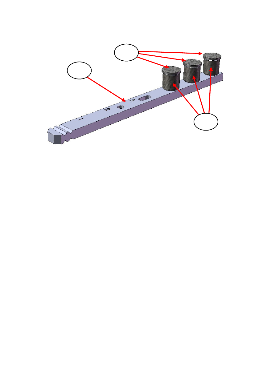
The diabraze pad (22) and mount (23) assembly is placed into the
Minidiff Plus for a sampling position being supported on its own
diabraze pad mount holder assembly (24). (See Fig 13.)
Page 27
Minidiff Plus Diffuse Reflectance Accessory
24
22
23
Fig 13. Minidiff Plus Diabraze Pad Mount Holder Assembly
The diabraze pad (22) can be used to transfer a sample type to the
diabraze pad surface by simple abrasion of the diabraze pad (22)
against the sample of interest. (e.g. the plastic surface of a moulded
part). It may be preferable to transfer a small amount of the sample
type this way to record a diffuse reflectance spectral measurement,
rather than being able to sample the plastic material itself by an
alternative method of spectral collection. (e.g. ATR – Attenuated Total
Reflectance.)
Note: Similar to the sample cup mount holder assembly (9), the
diabraze pad mounter holder assembly (24) has a mount pad
(23) fixed into sampling position 3. It may be preferable to use
this sampling position for the reference measurement when
fixing a diabraze pad (22) to the mount (23).
In summary, the sample cup (8) is preferable to use for the diffuse
reflectance measurement of powder type solid samples, whereas the
diabraze pad (22) can be used to collect “difficult to obtain” samples for
a diffuse reflectance measurement by transfer of the sample to the
diabraze pad (22) surface from abrasive contact.
25
Page 28

User Manual
26
Procedure for Measurement with the Sample Cup (8)
For any sampling measurement to be taken, a background reference
spectrum must be recorded first for comparison. When using the
sample cup (8) for sample measurements, normally the background
reference spectrum to use would be created from measurement of KBr
or KI powder material as used for the alignment procedure. (See
Section 5 page 16).
Collecting a Background Spectrum
Fill the sample cup (8) with either KBr or KI powder or any suitable
powder material that could act as an appropriate background “blank”
for your sample material.
Load the filled sample cup (8) into the sampling position as explained
in Section 5) page 15 and then collect and store a background
spectrum against the spectral acquisition parameters set on your
spectrometer system. (e.g. 16 scans at 4cm-1 resolution.)
Collecting a Sample Spectrum
When a background spectrum has been collected, remove the
background sample cup (8) from its sampling position and replace
with a new filled cup (8) with the powder sample to analyse. The
spectral acquisition parameter conditions for recording of a sample
spectrum should be identical to those for obtaining the background
reference spectrum.
As mentioned in Section 5), (See Fig 5.), the sample cup mount holder
(9) has three sampling positions to place a filled sample cup (8). Hence
on the sample cup mount holder (9) you may already wish to have
sample cup position 1 occupied for the blank reference material in a
sample cup (8) and the spare sample cup positions 2 and 3 for actual
samples. It is then a simple matter of turning the sample position screw
(13) accordingly to change the reference sample cup (8) from its
background blank sampling position at the 1 position to load a filled
sample cup (8) at the 2 or 3 position into the sampling position.
Page 29

Minidiff Plus Diffuse Reflectance Accessory
Procedure for Measurement with the Diabraze Pad (22)
Similar to use of a sample cup (8), for any sampling measurement to
be taken using the diabraze pad (22), a background reference
spectrum must be recorded first for comparison. When using the
diabraze pad (22) for sample measurements, normally the background
reference spectrum to use would be a spectral collection of the surface
of a clean, new diabraze pad (22) itself, before any sample has been
abraded for transference to the diabraze pad (22) surface.
Collecting a Background Spectrum
Take a new, clean diabraze pad (22), peel away the protective backing
to expose the adhesive surface and stick the pad centrally to its mount
(23). Fit the diabraze pad (22) and mount (23) onto one of the 3
location pin positions on the diabraze pad mount holder assembly (24).
To place the diabraze pad mount holder assembly (24) onto the sliding
support rod (12), first wind out the support rod (12) by clockwise
rotation of the sample positioning screw (13), until the support rod (12)
comes to its end stop position. Place the mount holder assembly (24)
into position on the two locating studs of the support rod (12) with the
diabraze pad (22) and mount (23) parts nearest towards the Minidiff
Plus optical unit. Rotate the sample positioning screw (13) anticlockwise, to position the diabraze pad (22) on its mount (23) centrally
beneath the ellipsoid mirror (5) for its sampling position. The
appropriate sample position number 1, 2 or 3 on the diabraze pad
mount holder assembly (24) is indicated by the alignment mark (14)
when the diabraze pad (22) is in its correct sampling position.
Collect and store a background spectrum against the spectral
acquisition parameters set on your spectrometer system. (e.g. 16
scans at 4cm-1 resolution.) for the new, clean diabraze pad (22).
Collecting a Sample Spectrum
When a background spectrum has been collected, remove the
diabraze pad (22) on its mount (23) from its sampling position and
27
Page 30

User Manual
28
then remove the diabraze pad (22) and mount (23) from its position on
the diabraze pad mount holder assembly (24).
Abrade the diabraze pad (22) surface against the sample of interest to
transfer the sample to the surface of the diabraze pad (22) for spectral
analysis.
Now, reposition the diabraze pad (22) on its mount (23) with the
sample coating back onto the diabraze pad mount holder assembly
(24) and proceed to load the sample into the Minidiff Plus for its
sampling position for a spectral collection. The spectral acquisition
parameter conditions for recording of a sample spectrum should be
identical to those for obtaining the background reference spectrum.
As mentioned in Section 5) for the sample cup holder mount assembly
(9), the diabraze pad mount holder assembly (24) has three sampling
positions to place a diabraze pad (12) as affixed to its mount (23).
(See Fig 13.) Hence on the diabraze pad mount holder assembly (24),
you may already wish to have position 1 occupied for a blank (no
sample coating) diabraze pad (22) and mount (23) and the spare
diabraze pad (22) and mount (23) positions 2 and 3 for actual samples.
It is then a simple matter of turning the sample position screw (13)
accordingly to change the reference blank diabraze pad (22) from its
sampling position to load a sample coated diabraze pad (22) at the 2
or 3 position into the sampling position.
Note: This method of sampling can be done assuming that the
reference diabraze pad (22) taken for the background
measurement is representative of all of the diabraze pad (22)
surfaces being used. For consistency of results between the
background and sample conditions in any spectral acquisition it
may be preferable to use the same diabraze pad (22).
Page 31

Minidiff Plus Diffuse Reflectance Accessory
8. Cleaning the Minidiff Plus after Use
When sampling has been completed using the Minidiff Plus accessory,
solid/powder samples that have been used in a sample cup (8) may be
emptied out of the sample cup (8) and saved for further purposes if
desired. The sample cup (8) may then be rinsed with water, followed
by methanol or acetone and then dried with clean tisue for further use.
If sampling has been carried out using a diabraze pad (22) on its
mount (23), peel away and remove the used diabraze pad (22) from
the mount (23) and throw the diabraze pad (22) away. The surface of
the mount (23) may need to be cleaned of any residual adhesive for
use when affixing a new diabraze pad (22). Acetone solvent can be
used to moisten a tissue to wipe away at any adhesive residues.
If there has been any spillage of sample within the Minidiff Plus
accessory, this should be cleaned away. If sample has fallen onto the
mirror assemblies (3) and (4) to contaminate the mirror surfaces, then
it’s possible the sample can be removed carefully by gently blowing it
away with air and using a fine haired brush.
Note: If possible, try to avoid actually touching or wiping the mirror
surfaces, as if scratches or blemishes are introduced to the
reflecting surface, the performance of the Minidiff Plus accessory
will be impaired.
When any sampling cups (8) and the Minidiff Plus accessory have
been cleaned after use, the accessory and any appropiate parts can
be stored in the original carry case for safe keeping until use next time.
29
Page 32

User Manual
30
9. Minidiff Plus Accessory “Bubble Numbers”
Part Identification List
(1) Fixing thumbscrew for front metal cover plate.
(2) Front metal cover plate.
(3) Adjustable double sided mirror assembly.
(4) Fixed single sided mirror assembly at base of unit.
(5) Fixed ellipsoid (domed) mirror at top of unit.
(6) Benchmark™ baseplate.
(7) Fixing thumbscrew of Minidiff Plus to Benchmark™ baseplate.
(8) Sample cup. (5mm diameter, 3mm deep for sample.)
(9) Sample cup mount holder assembly.
(10) Sample filler base part.
(11) Sample filler cap part.
(12) Adjustable support rod for mount holder assembly.
(13) Sample positioning screw.
(14) Alignment mark for sampling position 1, 2 or 3.
(15) Micrometer adjustment screw for beam focal point position.
(16) Magnet to engage with micrometer adjustment screw tip.
(17) Double sided mirror.
(18) Adjustable mirror mount for double sided mirror.
(19) Fixing cap head screws for adjustable mirror mount.
(20) Grub screw to unlock and rotate adjustable mirror mount.
(21) Grub screw to tilt double sided mirror.
(22) Diabraze pad. (9mm diameter for surface).
(23) Mount for diabraze pad.
(24) Diabraze pad mount holder assembly.
Page 33

Minidiff Plus Diffuse Reflectance Accessory
10. Minidiff Plus Accessory Spare Parts
Minidiff Plus Accessory
P/N GS04510 Minidiff Plus Accessory complete. (Specify spectrometer
to be used when ordering to receive appropriate
Benchmark™ baseplate.)
Minidiff Plus Parts
P/N GS04505 Sample cup mount holder assembly with 3 sampling
cups. (2 assemblies supplied.)
P/N GS04506 Diabraze abrasive pads, 9mm diameter. (Packet of 100
pads supplied.)
P/N GS04508 Diabraze pad mount holder assembly sample with 3
diabraze pad mounts (2 assemblies supplied.)
P/N GS03610 KBr powder. (50 g supplied.)
31
Page 34

User Manual
32
Minidiff Plus Diffuse
Serial Number
11. Minidiff Plus Accessory Serial Numbering
A Minidiff Plus accessory will be provided marked with an identifying
serial number. The serial number is a five figure number prefixed by a
letter and found on a silver coloured label.
If there are any issues arising in use of the Minidiff Plus accessory, it is
useful to have the serial number information to hand when contacting
Specac.
Please use the table below to make a note of the serial number for
your received Minidiff Plus accessory.
Reflectance Accessory
P/N GS04510
Page 35

Worldwide Distribution
France
Eurolabo - Paris.
Tel.01 42 08 01 28
Fax 01 42 08 13 65
email: [email protected]
Germany
L.O.T. - Oriel GmbH & Co,
KG - Darmstadt
Tel: 06151 88060
Fax: 06151 880689
email:[email protected]
Website: www.LOT-Oriel.com/de
Japan
Systems Engineering Inc. -Tokyo
Tel: 03 3946 4993
Fax: 03 3946 4983
email:[email protected]
Website: www.systems-eng.co.jp
Spain
Teknokroma S.Coop C. Ltda
Barcelona
Tel: 93 674 8800
Fax: 93 675 2405
email: [email protected]
Switzerland
Portmann InstrumentsAG
Biel-Benken
Tel: 061 726 6555
Fax: 061 726 6550
email: [email protected]
Website:www.portmann-instruments.ch
USA
Specac Inc.
414 Commerce Drive
Suite 175
Fort Washington
PA 19034, USA
Tel: 215 793 4044
Fax: 215 793 4011
United Kingdom
Specac Ltd. - London
River House, 97 Cray Avenue,
Orpington
Kent BR5 4HE
Tel: +44 (0) 1689 873134
Fax: +44 (0) 1689 878527
Registered No. 1008689 England
Page 36

Brilliant Spectroscopy™
www.specac.com
SPECAC INC.
414 Commerce Drive
Suite 175,
Fort Washington,
PA 19034, USA
Tel: 215 793 4044
Fax: 215 793 4011
River House, 97 Cray Avenue,
Tel: +44 (0) 1689 873134
Fax: +44 (0) 1689 878527
Registered No. 1008689 England
SPECAC LTD.
Orpington
Kent BR5 4HE
 Loading...