

Page 1
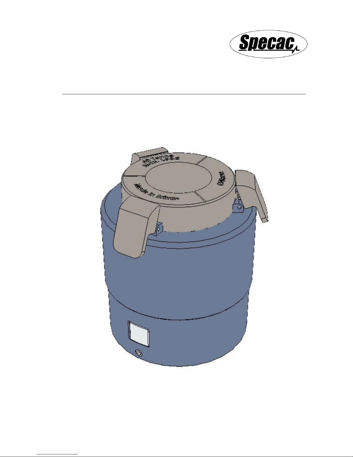
APEX Quick Release
Pellet Dies
User Manual
2I-26300-2
Page 2

Page 3

APEX Quick Release
Pellet Dies
User Manual
2I-26300-2
Page 4

User Manual
4
APEX Quick Release Pellet Dies
P/N GS26300 Series
CONTENTS
1.
INTRODUCTION
................................................................................. 5
2.
UNPACKING AND CHECKLIST
.............................................................. 9
3.
SAFETY AND APEX DIE CARE
............................................................ 10
4.
PREPARATION FOR USE OF THE APEX DIE
.......................................... 12
FITTING THE TOP PRESSING ANVIL TO A PRESS LEADSCREW
.............. 12
FITTING OF THE BASE LOCATOR PLATE
............................................. 13
5.
LOADING A SAMPLE IN THE APEX DIE
................................................. 16
FILLING THE APEX DIE WITH A SAMPLE
.............................................. 18
6.
PRESSING TO MAKE THE SAMPLE PELLET
.......................................... 20
7.
REMOVING THE APEX DIE FROM THE PRESS
....................................... 26
8.
DISASSEMBLY FOR THOROUGH CLEANING AND STORAGE OF THE APEX
DIE
................................................................................................. 27
DISASSEMBLY OF THE APEX DIE
....................................................... 27
REASSEMBLY OF THE APEX DIE
........................................................ 30
9.
LEGEND (BUBBLE PART NUMBERS) FOR THE APEX DIE
........................ 32
10.
SPARE PARTS FOR THE APEX DIE
.................................................... 33
© June 2018 Specac Ltd. All rights reserved.
Brilliant Spectroscopy is a trademark of Specac Ltd.
Other product names mentioned herein may be trademarks
of their respective owners.
Page 5

APEX Quick Release Pellet Dies
5
1. Introduction
Thank you for purchasing a Specac product.
The APEX Quick Release Pellet Dies have been specifically designed
to work with the range of Atlas™ Power and Autotouch Presses up to a
maximum load rating of 40 tonnes. The APEX Quick Release Dies are
also compatible for use with Specac’s 15 and 25 tonnes Atlas™
Manual Hydraulic Presses.
The APEX Quick Release Dies have an inner die body made of 440C
hardened stainless steel that is contained within an outer sleeve jacket
mechanism made of anodised aluminum components. The 440C die
body has a Mohs hardness rating of circa 7.5 for the pressing of solid
sample types (powders) into pellets with a similar or lesser hardness
rating. The complete APEX Die assembly is offered in two versions to
prepare solid sample pellets/discs of 40mm or 32mm diameter size.
Both APEX Die sizes are provided complete with a top pressing anvil
assembly and base locater plate for quick and easy use.
The design of the APEX Die for its outer sleeve mechanism allows for
the pellet sample to be automatically presented to the user without
the need to reconstruct the Die from a pellet forming to a pellet
releasing pressing stage during the pressing process.
When using a conventional, Standard Pellet Die, under a two-stage
pressing process the first stage is to compress a sample powder in the
Standard Die into a sample pellet and the second stage is to release
the sample pellet from the Standard Die body. Between the pressing
stages, the Standard Die must be removed from the Press to
exchange the pressing base with an extractor cap assembly and then
the Standard Die assembly of parts is inverted and placed back into
the Press. The ergonomics for a pressing procedure is greatly
simplified when using the APEX Quick Release Die and the time
required to produce a sample pellet is typically halved when compared
to use of a Standard Die.
Page 6
User Manual
6
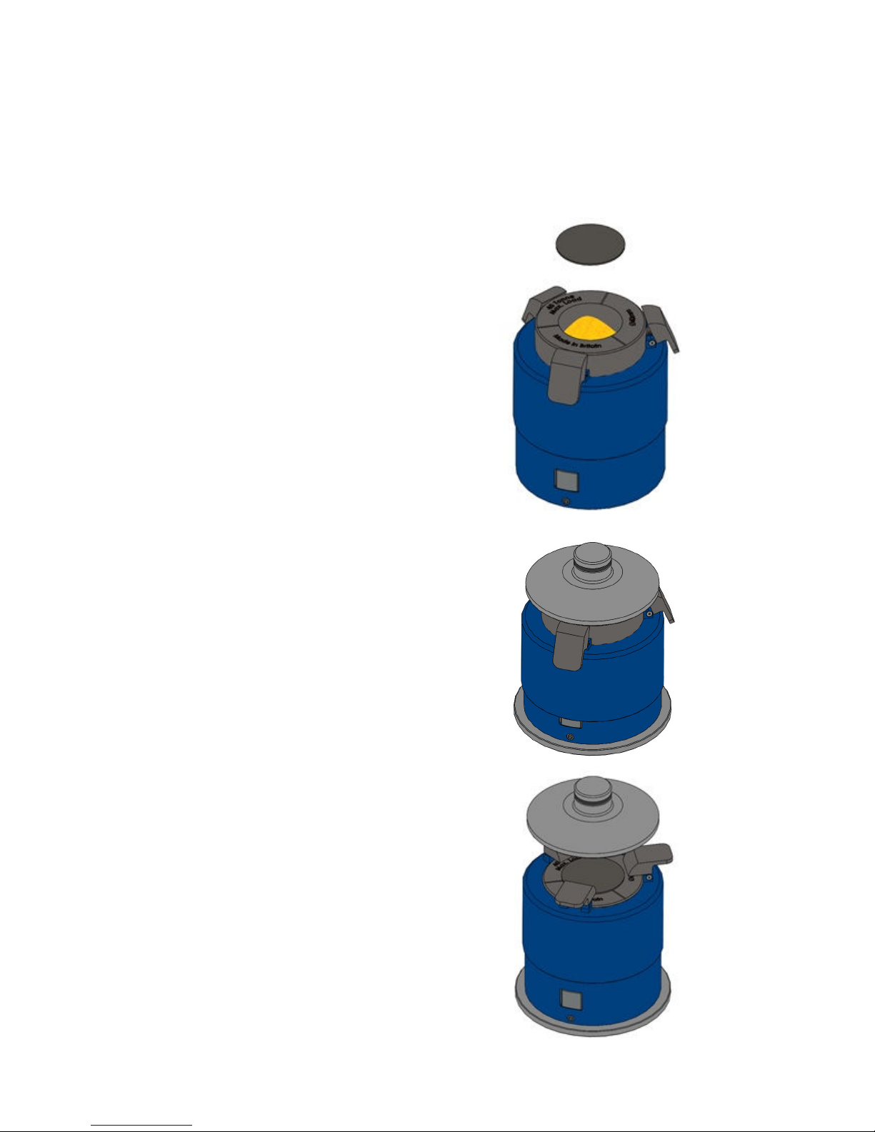
The typical procedure for the steps in use of the APEX Quick Release
Die are as follows:
Step 1 – Load Sample
The APEX Die is set to present
a cavity hollow at the top of the Die
to fill with sample inside the inner die
body. A stainless steel polished plate
is placed to cover over the top of the
die body containing the sample.
The inner die body and outer sleeve
parts are set to their load positions by
pressing the button on the inner sleeve
at the base.
Step 2 – Press Sample
The top pressing bolster anvil
fitted to the leadscrew of the
Press is brought into contact
with the APEX Die assembly and
a load to press is applied.
The sample within the internal
die body is compressed between
the stainless steel polished plate and
internal plunger of the APEX Die.
Step 3 – Sleeve Engages
The compression load is released
and as the top pressing anvil
separates away from the APEX Die,
the three spring tabs flip over to rest
on the top of the die body. The die
body is held in its compressed position
by an internal latching mechanism to
the sleeve assembly.
Page 7
APEX Quick Release Pellet Dies
7
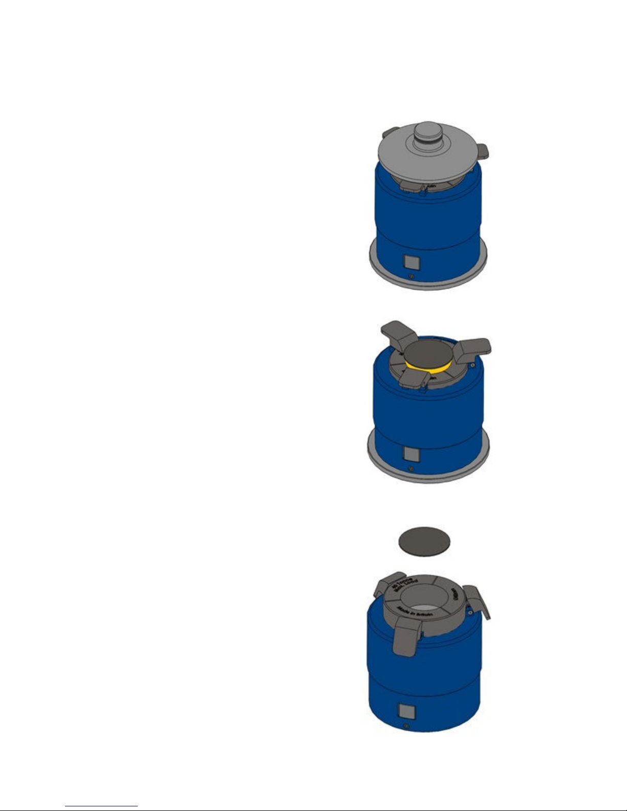
Step 4 – Press Again
Re-application of a low tonnage
load (up to 4 tonnes), in bringing
the top pressing anvil into contact
with the three spring tab surfaces,
will allow the internal plunger
to start pushing the sample
pellet towards the top of the
APEX Die.
Step 5 – Sample Released
When the second pressing stage
has completed and the top
pressing anvil is withdrawn away
from the APEX Die, the stainless
steel polished plate and pellet
sample is accessible from the top
of the APEX Die.
Step 6 – Clean and Reset
After removing the sample pellet,
clean the APEX Die components
and reset it to accept a new sample
by pressing the button on the inner
sleeve at the base (As Step 1.)
Page 8

User Manual
8
A powder sample or sample cup with powder that is placed into the
stainless steel die body of the APEX Die is compressed between the
polished surfaces of an internal plunger and a top stainless steel
polished plate. The top pressing anvil is permanently affixed into the
leadscrew assembly of any Specac Press for use of the APEX Die.
There are two top pressing anvils that are common for use with both
the 40mm and 32mm pellet APEX Dies. One top pressing anvil (P/N
GS26310) is specifically for fitting to the leadscrew assembly of
Specac Autotouch 40T Presses. The other top pressing anvil (P/N
GS26311) is for use with ANY other Specac Press (Manual, Power or
Autotouch variants.)
When using the APEX Die, it is very important to position the Die
centrally within the pressing sample compartment area of the Press.
To help for a quick and consistent positioning of the APEX Die
centrally in use, a base locator plate is provided with the APEX Die.
This circular locator plate has two dowel pins projecting from its upper
surface and is fitted over the main pressing piston part of a Specac
Press. The APEX Die is simply placed onto the base locator plate and
will be positioned centrally and correctly when the outer sleeve of the
APEX Die engages to touch both dowel pins.
The overall height of both the 32mm and 40mm APEX Dies is 118mm
when the reset button is pressed (Step 1). The maximum amount of a
solid or ground, powdered sample that can be placed into the APEX
die body at the load stage (Step 1), is limited to a depth of 20mm. A
maximum compacted pellet thickness is 7.5mm. When the APEX Die
is compressed under an applied, steady load (Step 2), the overall
height can be between 92mm to 98mm dependent upon a 1.5 to
7.5mm sample pellet thickness produced within.
The overall outer sleeve diameter of both 32mm and 40mm APEX Dies
is 90mm.
The dimensions and 2.7Kg weight of the APEX Quick Release Dies
are well suited for the preparation of solid pellets/discs for study by XRay Fluorescence (XRF) spectroscopy. Their ease and quickness of
use can assist in the production of a high number of pellet samples per
hour, depending on specific pressing tonnage load cycle regimes.
Page 9
APEX Quick Release Pellet Dies
9
2. Unpacking and Checklist
Remove the APEX Quick Release Die from its protective packaging.
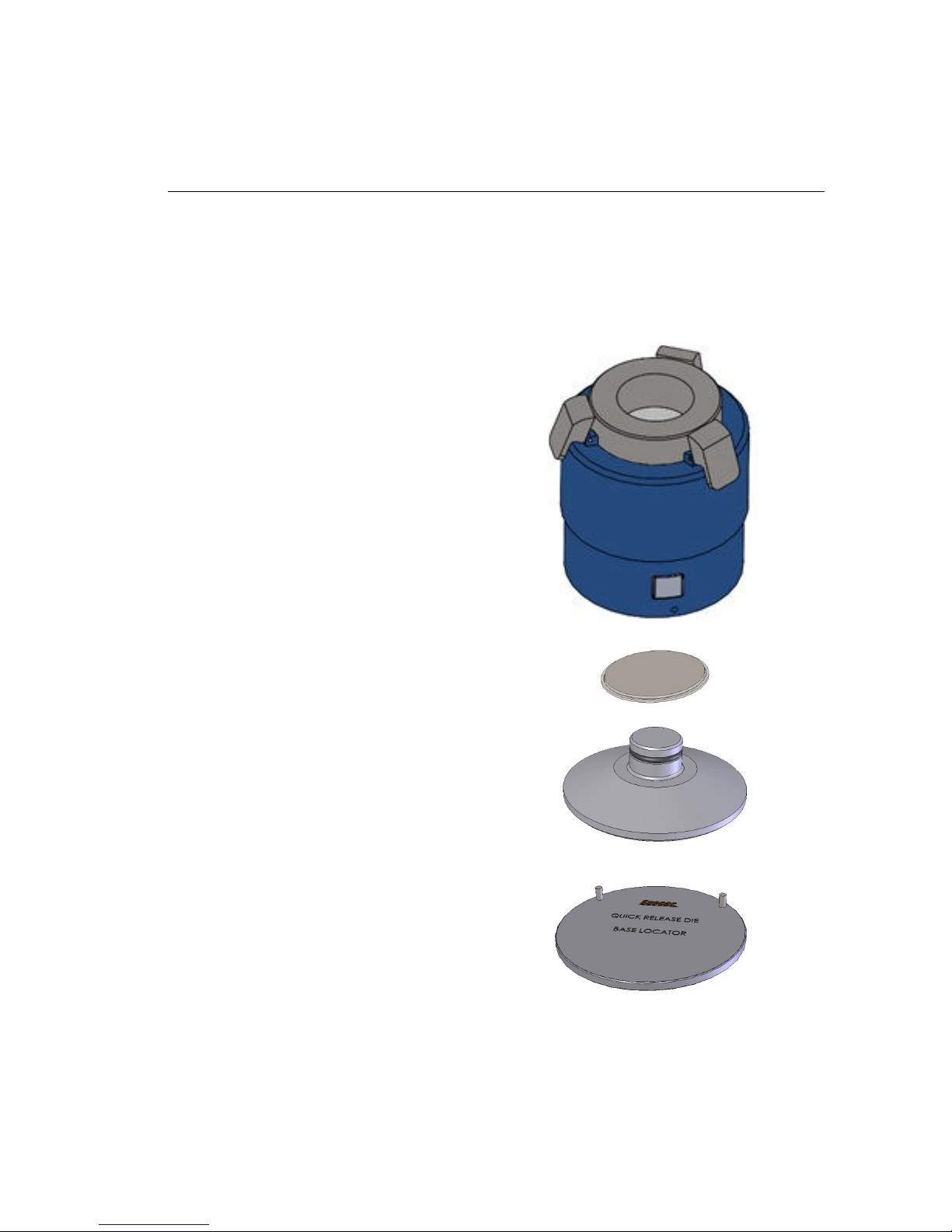
Please check that the following have been supplied:
A 40mm or 32mm APEX Die complete with associated parts.
To include:
• APEX Die complete assembly.
(As GS26301, GS26302,
GS26303 or GS26304)
• Top stainless steel
polished plate.
(GS26315 or GS26316)
• Top pressing anvil.
(GS26310 or GS26311)
• Base locator plate
(GS26330)
• 3mm A/F Allen key tool.
• 2mm A/F Allen key tool.
Page 10

User Manual
10
3. Safety and APEX Die Care
Safety
The APEX Quick Release Dies are inherently safe from correct use. It
may be that the sample type to press within the Die could pose the
most risk, so any health and safety instructions pertaining to the
sample type itself in its handling should be observed. However, when
the APEX Die is being used in a Press, any safety precautions
involved with operation of the Press itself must also be observed.
An APEX Quick Release Die must always be placed as centrally as
possible within the pressing area of a Press to provide a correct and
consistent evenness in loading when being compressed. The base
locator plate provided helps for a quick, easy and consistent way of
correctly positioning the APEX Die into a Press.
Warning!
Never exceed the stated maximum safe load of 40 tonnes
when pressing using an APEX Quick Release Die.
Die Care
The APEX Quick Release Die body, plunger, top pressing anvil and
top polished plate parts are made from corrosion resistant stainless
steel (440C), but because of the nature of certain materials that may
be used with the APEX Dies, it is necessary to take certain
precautions. Any sample to press that is harder than stainless steel in
having a Mohs value of higher than 7.5, risks damage to the parts.
Similarly, pressing of very fine particulate samples (smaller than the
minimum tolerance clearance values for the Dies), risks damage to
certain components.
Page 11

APEX Quick Release Pellet Dies
11
For most pressing operations, the APEX Die can be cleaned quickly
and simply between samples around the top surface area of the die
body (5) and against the surfaces of the pressing parts that have
contacted with the sample. (e.g. surfaces of the top polished plate (12)
and plunger (9)).
The APEX Die parts can usually be cleaned between samples initially
using a soft cloth or tissue paper dampened with warm or cold water
and finally with a soft dry cloth or tissue paper. After washing with
water, a cloth dampened with methanol may also be used to remove
any organic sample residues that may be present and any excess
methanol is wiped away with a soft dry cloth or tissue paper. When not
in use always ensure that the APEX Die and its component parts are
thoroughly clean and dry, and if possible store the APEX Die in a
desiccator.
Note: When cleaning the APEX Die parts, do not use a cloth that has a
hard, abrasive texture as scratches or imperfection to the
surfaces may result. Always use a soft cloth or tissue.
For a more thorough cleaning of the APEX Die if necessary, it has
been designed such that the internal die body (5), plunger (9) and
spring (8) components can be removed from the outer (6) and inner (7)
sleeve mechanism. Please see how to disassemble the APEX Die for
more thorough cleaning in Section 8, page 27 of this user instruction
manual.
Page 12
User Manual
12
4.Preparations for Use of the APEX Die
Fitting the Top Pressing Anvil to a Press Leadscrew
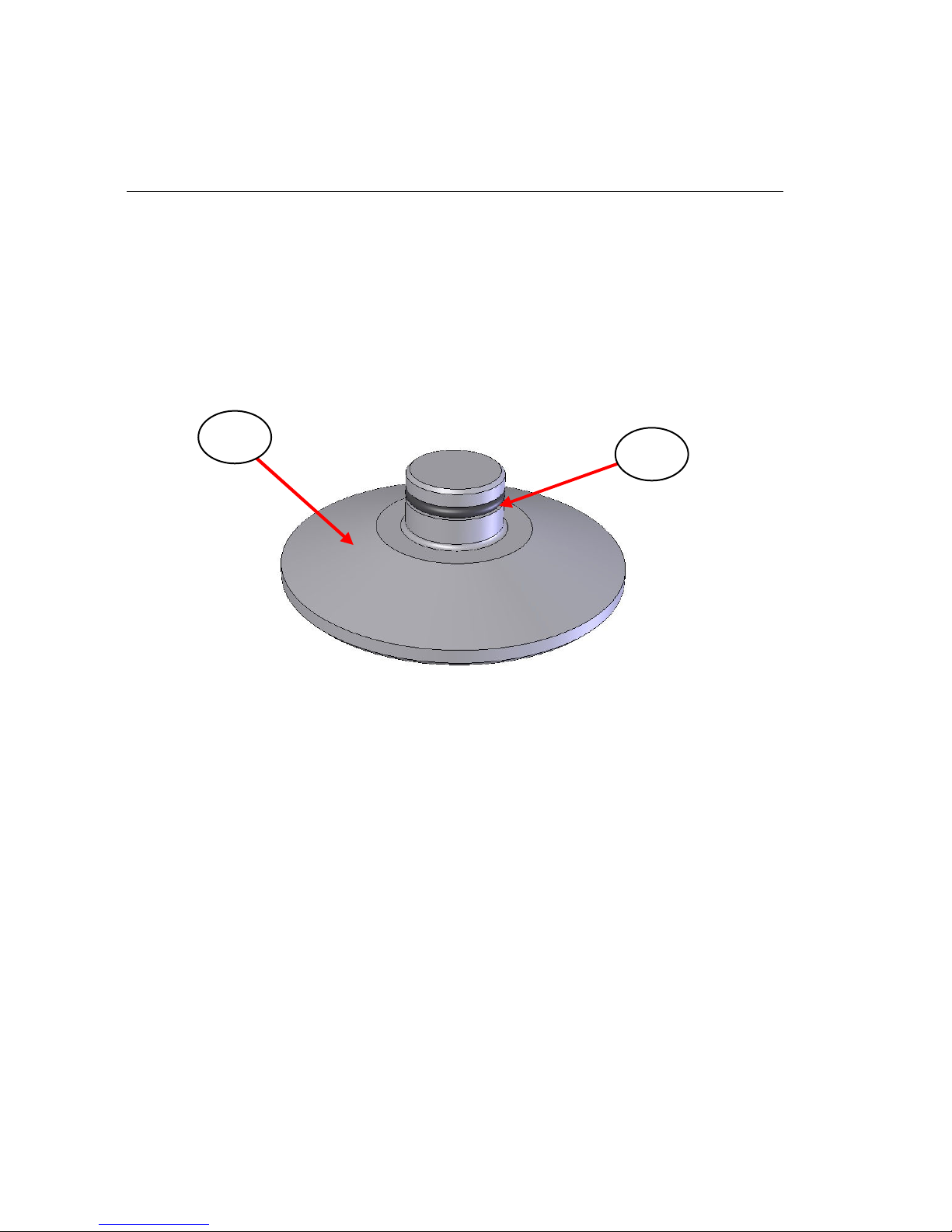
For use of the APEX Quick Release Die, there is a requirement to fit
the appropriate top pressing anvil (1) part into the leadscrew assembly
of the Press to be used.
Fig 1. Top Pressing Anvil Assembly
Fig 1. shows the top pressing anvil (1) with its securing O-ring (2).
A standard top bolster anvil as fitted to the leadscrew of the Press is
removed and is replaced by the new upper pressing anvil (1) for the
APEX Die. Both anvil types (standard bolster and APEX Die top
pressing anvil) are held into the hollow recess at the tip of the
leadscrew from a compression tight fit of the O-ring (2) on the anvils.
The standard anvil is carefully pulled out of the hollow tip of the
leadscrew and the APEX Die top pressing anvil (1) is pushed back into
place as far as it will go for the O-ring (2) to hold.
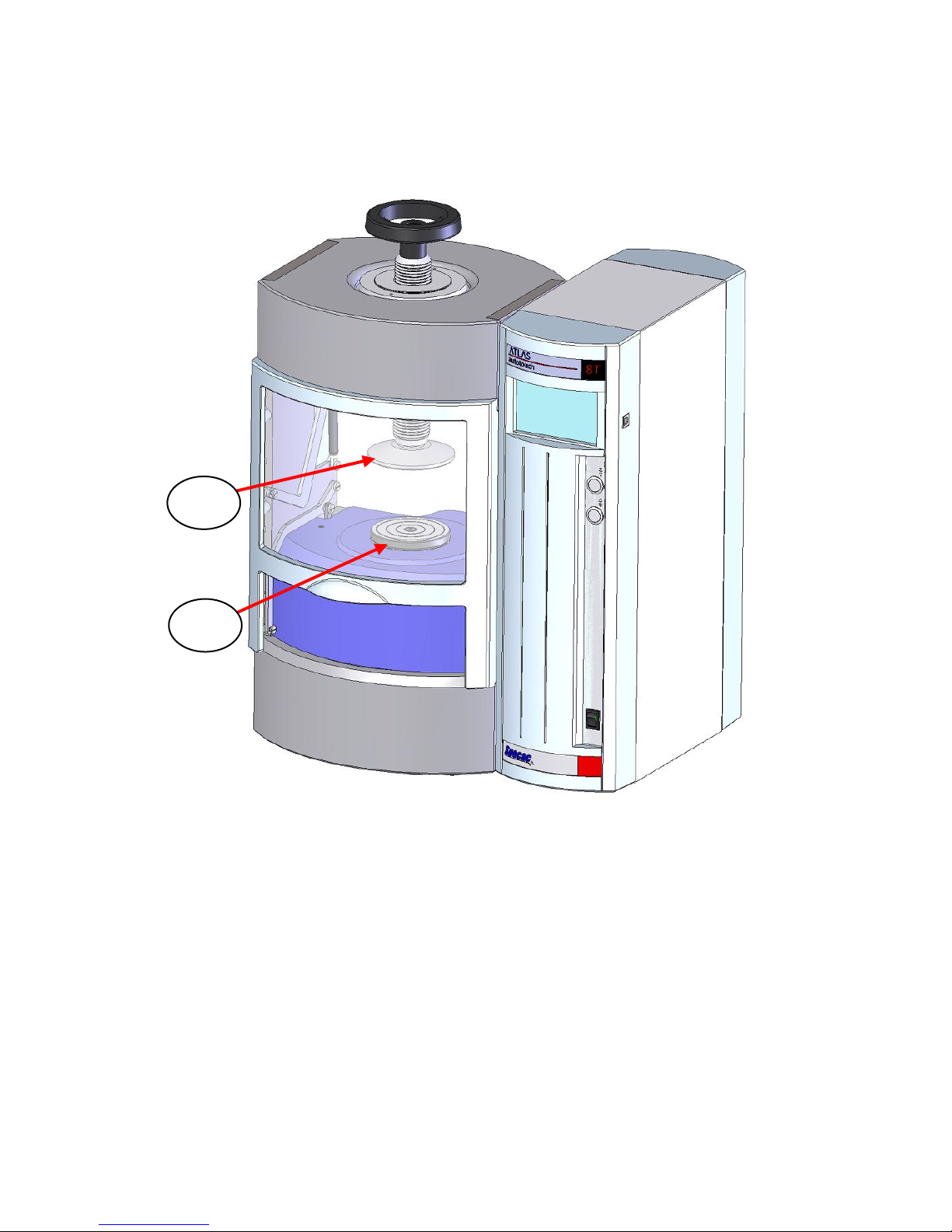
Note: For explanation, the top pressing anvil P/N GS26311 is shown
fitted into an Atlas Autotouch 8T Press at Fig 2. (For the Atlas
Autotouch 40T Press only, the top pressing anvil P/N GS26310
is used.)
1
2
Page 13
APEX Quick Release Pellet Dies
13
Fig 2. Top Pressing Anvil Fitted into the Leadscrew of the
Autotouch (8T) Press
Fitting of the Base Locator Plate into the Press
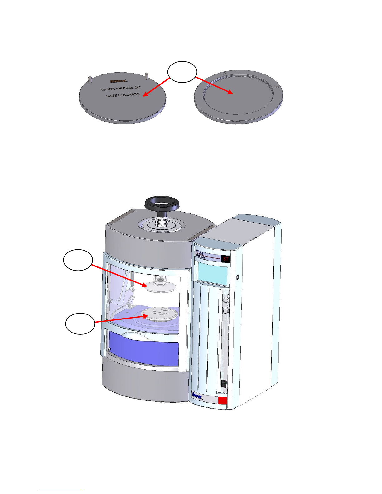
When the top pressing anvil (1) has been fitted, the base locator plate
(3) is placed into the Press to cover the lower pressing piston surface
(4). Fig 3. shows both the top and underside surfaces of the base
locator plate (3).
1
4
Page 14
User Manual
14
Fig 3. Base Locator Plate – Top (Left) and Underside (Right) Views
The circular recess on the underside surface of the base locator plate
(3) allows for this part to simply fit over the main piston pressing
surface of the Press for its correct and centralised positioning. (See
Fig 4.)
Fig 4. Base Locator Plate Fitted over the Piston Pressing
Surface of the Autotouch (8T) Press
3
3
1
Page 15
APEX Quick Release Pellet Dies
15
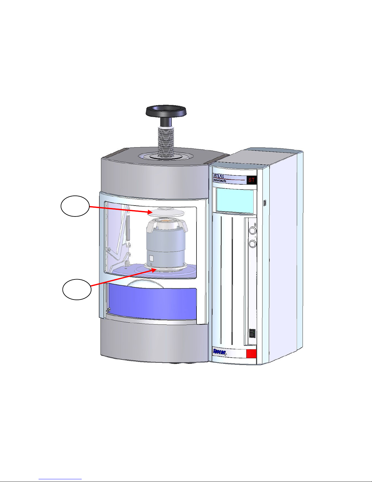
The two dowel location pins on the top surface of the base locator
plate (3) are used to centralise the APEX Die when it is placed into the
Press. The APEX Die is positioned such the outer sleeve diameter of
the APEX Die touches both dowel pins. (See Fig 5.)
Fig 5. QR Die installed between Top Pressing Anvil and Base
Locator Plate as fitted in the Autotouch (8T) Press
With both the top pressing anvil (1) fitted and base locator plate (3)
positioned in the Press, the APEX Die can now be used.
3
1
Page 16
User Manual
16
5. Loading a Sample in the APEX Die
The APEX Die can accept a powder or appropriate diameter sample
cup filled with powder once it has been initially set in its load sample
position. (See Apex Die Tips page 22.)
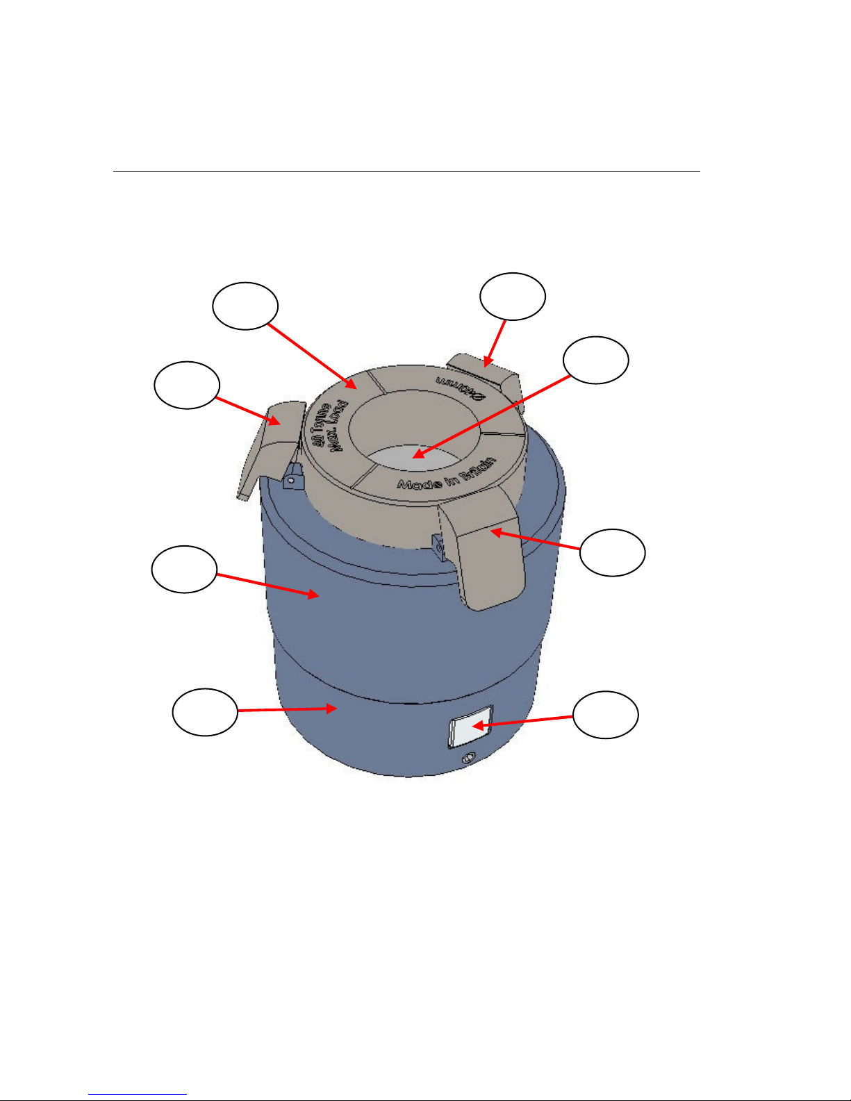
Fig 6. APEX Die Set for Sample Loading
Fig 6. shows the APEX Die complete assembly when set in its load
position for filling with a sample. The inner die body (5) sits within the
outer sleeve assembly (6) and is free to slide past the outer sleeve (6)
during any compression event. The outer sleeve assembly (6) is in turn
free to slide past the inner sleeve (7) assembly during any
compression event cycle.
7
6
11
10
10
5
10
9
Page 17

APEX Quick Release Pellet Dies
17
The die body (5) is supported by an internal spring (8) (not shown) that
is in turn connected to the plunger (9). During a compression event
from application of a load to the APEX Die, the die body (5) is forced
downwards to compress the spring (8) and the plunger (9) pressing
face travels in an upwards direction within the bore of the die body.
The sample itself is compressed between the faces of the top pressing
anvil (1) or top polished plate (12) and the plunger (9) as contained
within the bore of the die body (5).
Note: The tolerance of fit is 10 microns minimum and 30 microns
maximum between the outer circumference surface of the
plunger (9) and walls of the Die body (5) inner cylinder surface.
On the outer sleeve assembly (6) there are three hinged tab pieces
(10) that rest against the outer circumference of the die body (5). In the
load position they rest as seen in Fig 4. against the die body, but after
a sample has been compressed in the APEX Die and with release of
the applied load from the Press to the APEX Die assembly, the hinged
tab pieces (10) automatically engage to flip over to form a new
pressing surface level at the top of the APEX Die. (See Step 3, page
6). It is this automatic deployment of the tab pieces (10) to their flipped
over position that allows for an immediate second pressing stage to be
applied to the APEX Die assembly to gain quick and easy access to
the sample pellet that has been pressed.
On the inner sleeve assembly (7) there is a button (11). Depression of
this button releases any compression that has been applied to the
spring (8) which is held under compression by an internal ratchet
locking mechanism for the die body (5).
Note: Pressing of the button (11) resets the APEX Die to its start set
position but not for its sample load latched position seen as
at Fig 6. The load latched position must be set to fill the Die.
Warning!
Keep hands/fingers away from the three hinged tabs (10)
when the reset button (11) is pressed. Hold the APEX Die
towards the bottom of the outer sleeve (6) with one hand,
whilst pressing the reset button (11).
Page 18

User Manual
18
Filling the APEX Die with a Sample
Having pressed the button (11) to reset the APEX Die, push down on
the die body (5) to hold for its first latching position against the outer
sleeve assembly (6) before filling with a sample. (See APEX Die Tips
page 22.) A solid powder sample can be transferred for filling the die
body (5) using a spatula or by making a paper chute or funnel.
Note: If filling the die body (5) to a depth of circa 10mm with a powder
sample to compress, a circa 8ml volume of sample is used with
the 32mm Die and circa 12.5ml of sample with the 40mm Die.
For a mass of sample, Specac suggest typically 4 to 5 grams for
the 32mm size and 6 to 8 grams for the 40mm size Die is used.
If using an aluminium or plastic support cup with a solid sample,
ensure that an empty support cup is first placed into the die body (5)
and pushed towards the surface of the plunger (9) within the die body.
Note: If using a support cup, the amount of solid sample powder that
you should place into the die body (5) should be sufficient to
cover over the support cup completely but to no more than the
20mm uncompacted sample depth limit for the die body.
When all the sample powder to be compressed has been placed into
the die body (5), use the tip of a spatula to spread the powder such
that it has a flat, evenly distributed surface. Preparation of the
uncompacted powder surface helps to produce a more homogenously
compressed sample pellet. An uncompacted powder sample depth
limit is up to 20mm maximum within the die body (5), with use of the
top polished plate (12).
Important! Before any pressing is to take place ensure the top surface
level area of the Die Body (5) is clean and free of sample.
Any sample residues above the maximum sample depth
limit within the bore of the Die Body or that spill over
around the top edge, may impede the top polished plate
(12) for contact and fit and compromise for a correct
pressing of the sample within the Die Body (5) itself.
Page 19
APEX Quick Release Pellet Dies
19
When the die body (5) is filled correctly with a sample, the top polished
plate (12) is correctly positioned over the top of the Die Body (5). (See
Fig 8.)
The Top Polished Plate
The top polished plate (12) is provided with an appropriate 32mm or
40mm diameter pressing surface to match the size of APEX Die being
used.
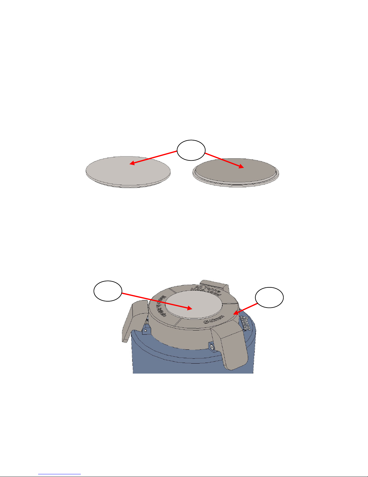
Upper Surface Underside Surface
Fig 7. Top Stainless Steel Polished Plate
Only one surface of the plate (12) is polished and this surface must
be in contact with the sample to be pressed. Fig 7. shows the top
polished plate (12) for its upper and underside surfaces. The
underside surface is polished and is the matching diameter of 32mm
or 40mm to fit inside the die body (5).
Fig 8. Top Polished Plate fitted over APEX Die Body
With the top polished plate (12) fitted, the APEX Die can be installed
into a Press. (See Fig 9.)
12
12
5
Page 20
User Manual
20
6. Pressing to Make the Sample Pellet
Place the prepared APEX Die with sample in its upright position
carefully into a Press fitted with a top pressing anvil (1) and lower base
locator plate (3).
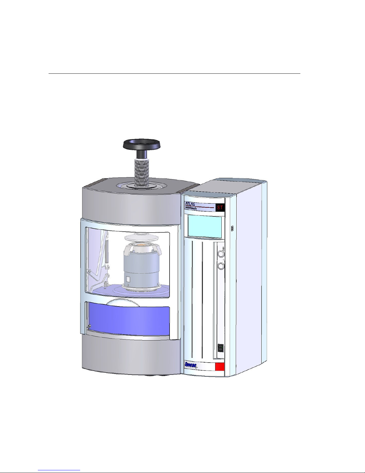
Fig 9. APEX Die with Sample as Fitted into a Press
(Autotouch (8T) Press shown as example)
Page 21

APEX Quick Release Pellet Dies
21
With the APEX Die fitted correctly and centrally into a Press, a load to
compress the sample can be applied.
The way a load can be applied to the APEX Die and sample depends
upon the Press to be used. The APEX Die can be used in all Specac’s
range of Manual, Power and Autotouch Presses.
Fig 9. shows the APEX Die with a sample to compress as installed into
an Atlas™ Autotouch Press. Specifically, the Autotouch Presses can
be programmed to apply a set load for a known time duration and to
release the load automatically as an unattended pressing operation
from the push of a button. A custom program can be created
specifically on the Autotouch Press that allows for the quick release
features of the APEX Die to be used most ergonomically.
The custom program to create will allow for the first stage in pressing
the sample powder into a pellet from application of a load within the
pressing range limit of the Press being used. (e.g. up to 15 tonnes if an
Autotouch 15T Press is used.). After the load has been reached and
held for as long as required, the load can be released to zero tons to
allow the piston of the Press to retract to a resting position. If there is
sufficient travel of the Press piston in retraction to its start/rest point,
the APEX Die can configure itself automatically to the position of where
the three hinge tab pieces (10) flip over to rest on top of the die body
(5) (when the outer sleeve (6) engages), and the APEX Die is now set
to be pressed further for a release of the pellet. The final steps of the
custom program can be application of a low tonnage load to push the
plunger (9) through the die body (5) to present the sample pellet and
top polished plate (12) at the top of the die body (5) for access and to
release the applied load to end the complete program sequence.
Follow the specific instructions for operation of your Press to apply a
load to the APEX Die assembly. The APEX Quick Release Dies have a
maximum load limit of 40 tonnes.
Warning!
DO NOT EXCEED THE MAXIMUM LOAD.
Page 22
User Manual
22
Keep the load applied from the Press to the APEX Die assembly for
however long it is necessary to produce an acceptable sample pellet.
The pressing sequence in use of the APEX Die can be followed as
seen from Step 1 to Step 5 in the Introduction Section (pages 6 and 7)
of this User Instruction Manual. When Step 5 has been completed the
APEX Die with Sample can be removed from the Press.
APEX Die Tips/Warnings
There are a few steps to observe for a correct set up and operation of
the APEX Die. (Please also see APEX Die First Run Set Up Guide
provided in addition to this User Instruction Manual.)
Set Up for Sample Filling
Warning! The APEX Die assembly must be set to the 1st “Click” latch
position before filling with a sample and placing in a Press.
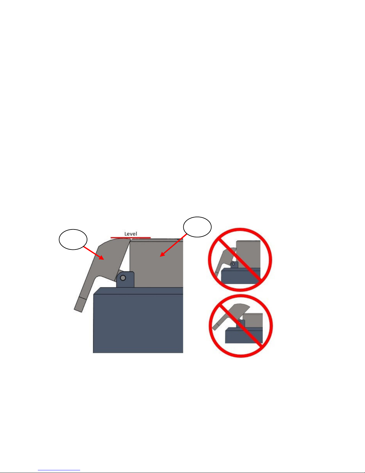
Top of APEX die body (5) at the 1st latch position with hinge tab
pieces (10) level with the top of the die body
To set to the 1
st
click latch position for sample filling, push down on the
die body (5) after pressing the reset button (11) until the die body top
surface holds level with the three hinged tab pieces (10).
10
5
Page 23
APEX Quick Release Pellet Dies
23
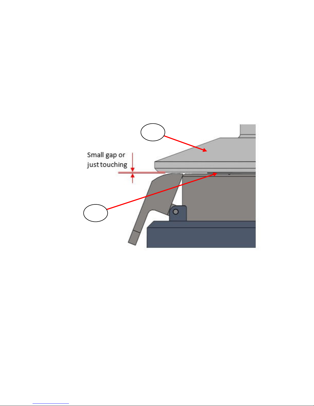
Set Up for Placing a Filled APEX Die in a Press
When the APEX Die is filled with a sample and the top polished plate
(12) is fitted, the complete Die assembly can be put in a Press onto the
base locator plate (3). Lower the leadscrew of the Press fitted with the
top pressing anvil (1) downwards, ideally to leave a very small gap
between the top polished plate (12) and the anvil (1) pressing surface
before commencing with pressing in application of a load from
pumping of the Press itself.
Warning! The top polished plate (12) and anvil (1) components can be
brought into contact to touch prior to an actual pressing of a
load applied from the Press. However, do not attempt to
further compress the Die using the leadscrew at this set
up stage. Any load application for compression of the
sample must be provided from the Press to allow for
sufficient movement of the APEX Die mechanism and avoid
potential damage to the hinge tab pieces (10) if they haven’t
engaged correctly to flip over horizontally to rest on the top
of the die body (5) at the completion of the pressing stage
for step 3 (sleeve engages), see page 6.).
1
12
Page 24

User Manual
24
Set Up – Powder Overfill Effect on Sample Release
Warning! Do not over-fill the Die with a sample. There is an
uncompacted powder sample depth of 20mm maximum
within the die body (5) to allow for fitting of the top polished
plate (12) prior to any pressing of the APEX Die.
Depending upon an initial fill and depth of sample into the die body (5),
if any subsequent compressed sample pellet thickness is >7.5mm,
then the sample pellet may be crushed when undergoing the pellet
extraction stages from steps 4 and 5 in the pressing cycle (See
incorrect operation image 2) on page 25.)
If the die body (5) is overfilled too much prior to any pressing cycle for
a subsequent load to be applied from the Press, then the hinge tab
pieces (10) may not engage correctly due to an insufficient
compression of the sample within the die body (5). Depending on
whether too much or even too little sample is placed into the die body
(5) prior to initial compression from an applied load, it is an operational
requirement of the APEX Die that an overall travel of at least 13mm of
the Press piston component pushing from below against the APEX Die
assembly is achieved.
Note: A stated 13mm minimum piston travel for correct operation is
conditional on the set up of the APEX Die for a fill of sample into
the die body (5) at the recommended 1st latch position. (See
page 22.)
At the subsequent pellet extraction pressing stages (steps 4 and 5 in
the pressing cycle), the hinge tab pieces (10) could be damaged if they
have not engaged correctly from completion of the pressing stage at
step 3 for the required Press piston travel. (See incorrect operation
images 3) and 4) on pages 25 and 26.) If the expected thickness of a
sample pellet is unknown after an initial amount of sample has been
placed in the APEX Die and been subjected to a specific load
application from the Press, Specac recommend for a pause in a
pressing cycle to check that the hinge tab pieces (10) have all engaged
correctly after pressing step 3, before continuing to steps 4 and 5 for
release and access of the sample pellet.
Page 25
APEX Quick Release Pellet Dies
25
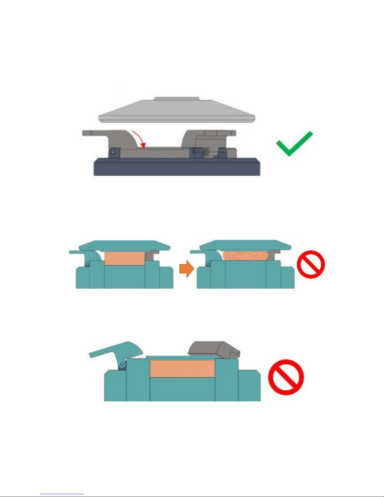
The following images help illustrate the effects of correct 1) and
incorrect 2), 3) and 4) sample filling in set up for operation of the APEX
Die.
1) Sample has compressed, anvil (1) is released and hinge tab
pieces (10) parts lie flat on the die body (5)
2) Compressed sample too thick – sample crushed when
released.
3) Compressed sample too thick – hinge tab pieces (10) cannot
flip over to rest horizontally on top of die body (5).
Page 26
User Manual
26
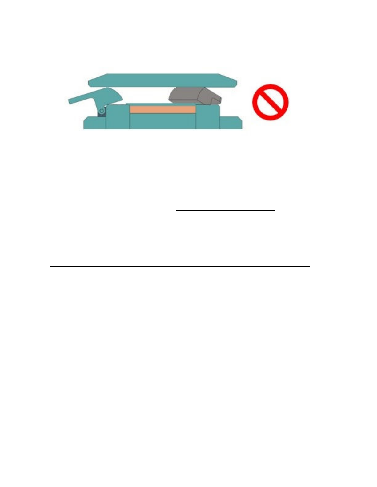
4) Insufficient Press piston travel for sample compression
pressing stage preventing hinge tab pieces (10) to engage
correctly.
If any of the pressing situations 2), 3) or 4) are encountered from an
incorrect filling of the APEX Die after compression of an applied load to
a sample powder, please contact [email protected] to help if
you have difficulty in removing a sample pellet that is too thick from the
die body (5).
7. Removing the APEX Die from the Press
When the APEX Die assembly with powder sample has been
compressed and the sample pellet as formed is accessible from a
release of any applied load (Step 5 is completed – see page 7),
remove the complete APEX Die assembly carefully from the Press.
The prepared, compacted sample pellet can now be analysed by an
appropriate technique.
The APEX Die assembly can now be cleaned as described (see Die
Care – pages 10 and 11) in readiness for a new sample from a reset of
the Die (Step 6).
However, the APEX Die can be disassembled if necessary for more
thorough cleaning of the die body (5), spring (8) and plunger (9)
components. (See Section 8 – page 27.)
Page 27

APEX Quick Release Pellet Dies
27
8. Disassembly for Thorough Cleaning and
Storage of the APEX Die
When the APEX Quick Release Die is not in use, ensure it is clean and
stored correctly. (See Die Care – pages 10 and 11.)
Depending on the sample types (inorganic or organic chemicals) that
have contacted with the parts of the APEX Die, all can usually be
removed by a combination of washing with warm or cold water,
followed by rinsing with methanol and then drying with soft tissue or a
cloth.
The cleaned APEX Die parts can be stored in a desiccator, in a
warming cabinet or left on a warm (35°C) hot plate. When drying with a
cloth ensure the material is non-abrasive to protect from scratches
being made to the APEX Die parts.
Disassembly of the APEX Die
During use of the APEX Die, if it becomes heavily contaminated from
powder sample residues etc, a simple cleaning between samples may
not be sufficient. Hence, the APEX Die has been designed to separate
the die body (5), spring (8) and plunger (9) components away from the
outer (6) and inner (7) sleeve mechanism assembly for greater
accessibility in their cleaning.
To gain access to the inner pressing components of the APEX Die, set
the APEX Die to its load sample position from pressing the button (11).
Now, very carefully invert the APEX Die assembly and stand it upright
as shown in Fig 10. (Page 28)
On the inner sleeve (7) assembly there are three (3mm A/F) grub
screws (13) around the base circumference. These grub screws hold
the plunger (9) into position with the inner sleeve (7) assembly.
Carefully loosen the three grub screws (12) by unscrewing them
anticlockwise a couple of full turns using the 3mm A/F Allen tool
Page 28
User Manual
28
provided. It is not necessary to remove these grub screws completely
from the inner sleeve (7) assembly.
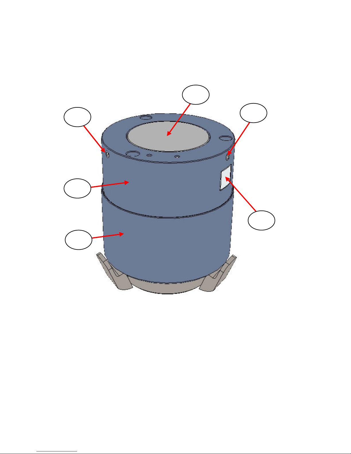
Fig 10. APEX Die in Set/Load Position and Inverted
When the three grub screws (13) have been loosened sufficiently the
outer (6) and inner (7) sleeve assembly parts can be pulled up and
away from the die body (5), spring (8) and plunger (9) parts assembly.
The release button (11) should be pressed while lifting the sleeve
assembly up, to release the internal ratchet locking mechanism.
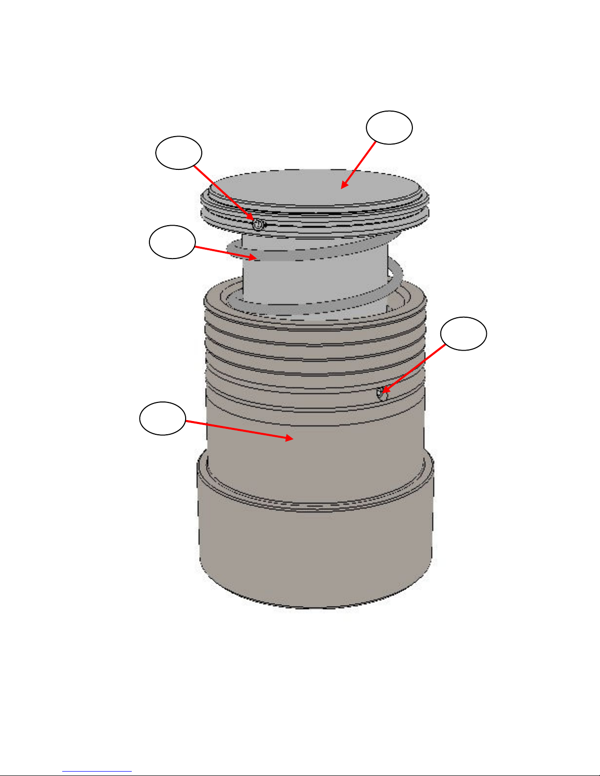
Fig 11. shows the assembly of parts when the outer (6) and inner (7)
sleeve assembly has been removed.
13
9
13
11
7
6
Page 29
APEX Quick Release Pellet Dies
29
Fig 11. APEX Die, Die Body, Spring and Plunger Assembly
9
8
5
14
15
Page 30
User Manual
30
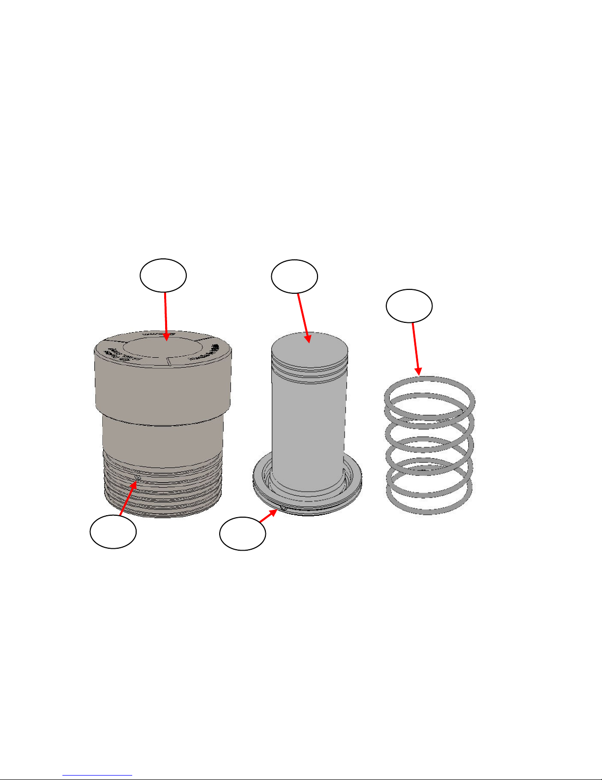
When the die body (5), spring (8) and plunger (9) assembly has been
accessed, it is further dis-assembled into its individual component
parts for more thorough cleaning of these items. (See Fig 12.)
Using the 2mm A/F Allen tool provided, loosen the single (2mm A/F)
grub screw (14) from the side of the die body (5) to free the spring (8),
leaving the spring attached to the plunger (9). Now loosen the single
(2mm A/F) grub screw (15) at the base of the plunger (9) using the
same Allen tool to free the spring (8) away from this assembly of parts.
Fig 12. Individual Components of Die Body, Plunger and Spring
Reassembly of the APEX Die
Once the parts have been cleaned, the APEX Die is reassembled as a
reverse procedure.
5
9
8
14
15
Page 31
APEX Quick Release Pellet Dies
31
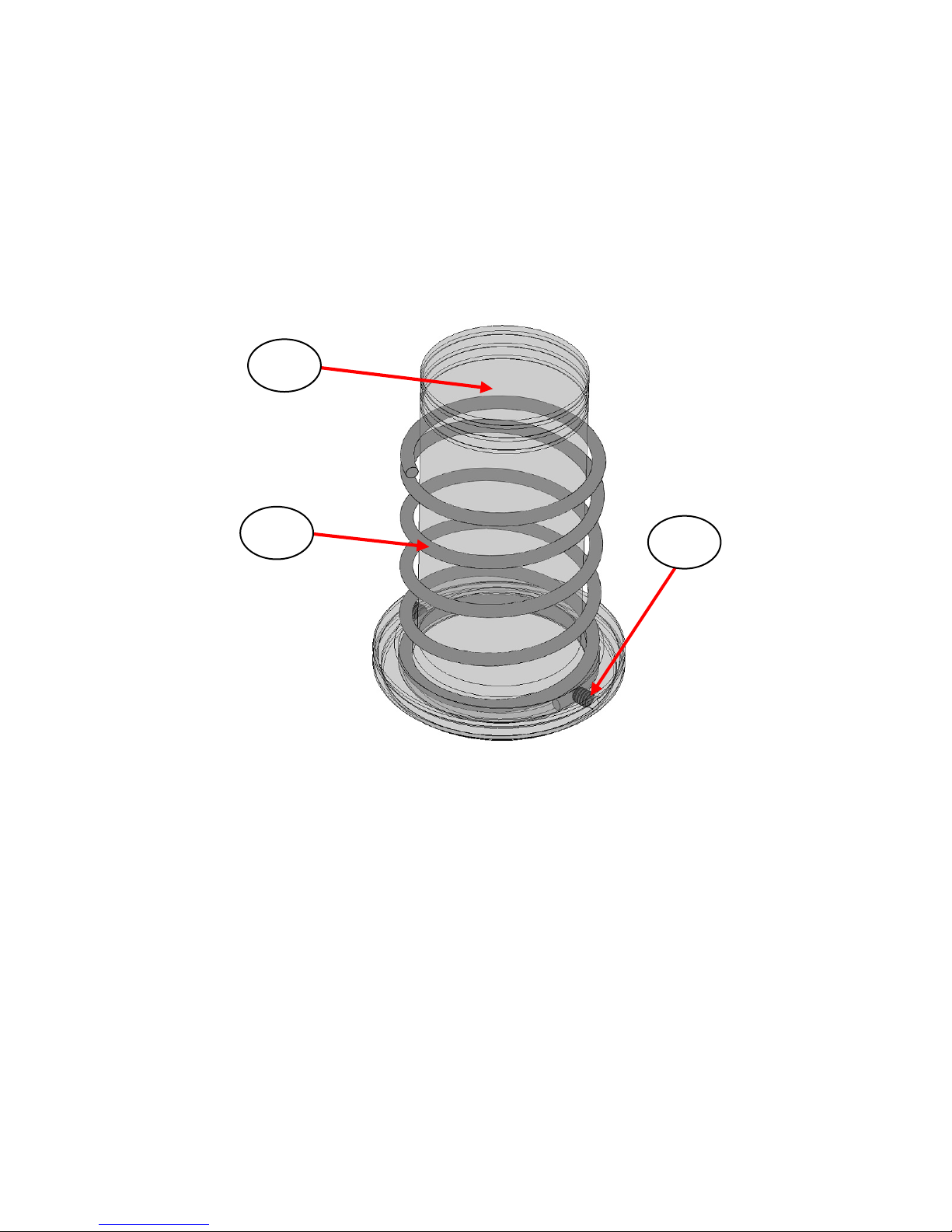
1) Fit the spring (8) over the plunger (9) such that the end of the
spring is a few mm past the grub screw (15) fixing before
tightening of this single grub screw (15). (See Fig 13.)
Compress the spring slightly while tightening the grub screw
ensuring it locks into place correctly.
Fig 13. Reassembly of Spring to Plunger for APEX Die
2) Now place the spring (8) and plunger (9) assembly of parts
back into the die body (5). Align the plunger (9) carefully into
the bore of the die body (5) and push in. Make sure the spring
(8) is positioned and compressed in a similar way for
tightening of the single grub screw (14) on the die body (5) to
hold the spring (8) and plunger (9) parts in place.
3) Invert this assembly as shown at Fig 11.
9
8
15
Page 32

User Manual
32
4) Slide the outer (6) and inner (7) sleeve assembly back over the
inverted die body/spring/plunger assembly.
5) Reposition the inner sleeve (7) parts correctly for alignment of
the 3 grub screws (13) around the base of the plunger (9).
6) Retighten the 3 grub screws (13).
7) Reinvert the complete APEX Die assembly in readiness for
use with a new sample.
9.Legend for the APEX Quick Release Die
(1) Top pressing anvil for APEX Die.
(2) O-ring on top pressing anvil.
(3) Base locator plate for APEX Die.
(4) Press piston surface.
(5) Die body.
(6) Outer sleeve assembly.
(7) Inner sleeve assembly.
(8) Spring.
(9) Plunger.
(10) Spring hinge tab.
(11) Button to reset APEX Die.
(12) Top stainless steel polished plate.
(13) Grub screw to lock plunger (9) to inner sleeve (7).
(14) Grub screw holding plunger (9) to spring (8).
(15) Grub screw holding spring (8) and plunger (9) to Die body (5).
Page 33

APEX Quick Release Pellet Dies
33
10.Spare Parts for the APEX Quick Release Die
Complete Dies
P/N GS26301 – 40mm APEX Quick Release Die with top pressing
anvil and base locator plate for 8T, 15T, 25T
Autotouch Press.
P/N GS26302 – 32mm APEX Quick Release Die with top pressing
anvil and base locator plate for 8T, 15T, 25T
Autotouch Press.
P/N GS26303 – 40mm APEX Quick Release Die with top pressing
anvil and base locator plate for 40T Autotouch Press.
P/N GS26304 – 32mm APEX Quick Release Die with top pressing
anvil and base locator plate for 40T Autotouch Press.
Individual Spares
P/N GS26325 – Die body for 40mm APEX Quick Release Die.
P/N GS26326 – Die body for 32mm APEX Quick Release Die.
P/N GS26321 – Plunger for 40mm APEX Quick Release Die.
P/N GS26322 – Plunger for 32mm APEX Quick Release Die.
P/N GS26310 – Top pressing anvil assembly of APEX Dies for the 40T
Autotouch Press.
P/N GS26311 – Top pressing anvil assembly of APEX Dies for the
15T/25T Manual and 8T/15T/25T Power/Autotouch
Presses.
P/N GS26315 – Top stainless steel polished plate 40mm dia.
P/N GS26316 – Top stainless steel polished plate 32mm dia.
P/N GS26330 – Base locator plate for APEX Dies.
P/N GS26340 – Spring for APEX Dies, (Includes 2 spare locking
grub screws.)
P/N GS26341 – Essential Spares Kit for Apex Dies (hinge tab spare
springs, fixing screws and grub screws).
P/N GS26351 – 40mm APEX Quick Release Die (no top pressing anvil
and no base locator plate).
P/N GS26352 – 32mm APEX Quick Release Die (no top pressing anvil
and no base locator plate).
Page 34

User Manual
34
Blank Page for Notes in Use of APEX Die
Page 35

Worldwide Distribution
France
Eurolabo - Paris.
Tel.01 42 08 01 28
Fax 01 42 08 13 65
email: [email protected]
Germany
L.O.T. - Oriel GmbH & Co,
KG - Darmstadt
Tel: 06151 88060
Fax: 06151 880689
email:[email protected]
Website: www.LOT-Oriel.com/de
Japan
Systems Engineering Inc. -Tokyo
Tel: 03 3946 4993
Fax: 03 3946 4983
email:[email protected]
Website: www.systems-eng.co.jp
Spain
Teknokroma S.Coop C. Ltda
Barcelona
Tel: 93 674 8800
Fax: 93 675 2405
email: [email protected]
Switzerland
Portmann InstrumentsAG
Biel-Benken
Tel: 061 726 6555
Fax: 061 726 6550
email: [email protected]
Website:www.portmann-instruments.ch
USA
SPECAC INC.
414 Commerce Drive
Suite 175,
Fort Washington,
PA 19034, USA
Tel: 215 793 4044
Fax: 215 793 4011
United Kingdom
Specac Ltd. - London
River House, 97 Cray Avenue,
Orpington
Kent BR5 4HE
Tel: +44 (0) 1689 873134
Fax: +44 (0) 1689 878527
Registered No. 1008689 England
Page 36

Brilliant Spectroscopy™
www.specac.com
SPECAC INC.
414 Commerce Drive
Suite 175,
Fort Washington,
PA 19034, USA
Tel: 215 793 4044
Fax: 215 793 4011
SPECAC LTD.
River House, 97 Cray Avenue,
Orpington
Kent BR5 4HE
Tel: +44 (0) 1689 873134
Fax: +44 (0) 1689 878527
Registered No. 1008689 England
 Loading...