

Page 1
Schedule 40 Fittings Technical
.
Schedule 40 Fittings Dimensions & Information
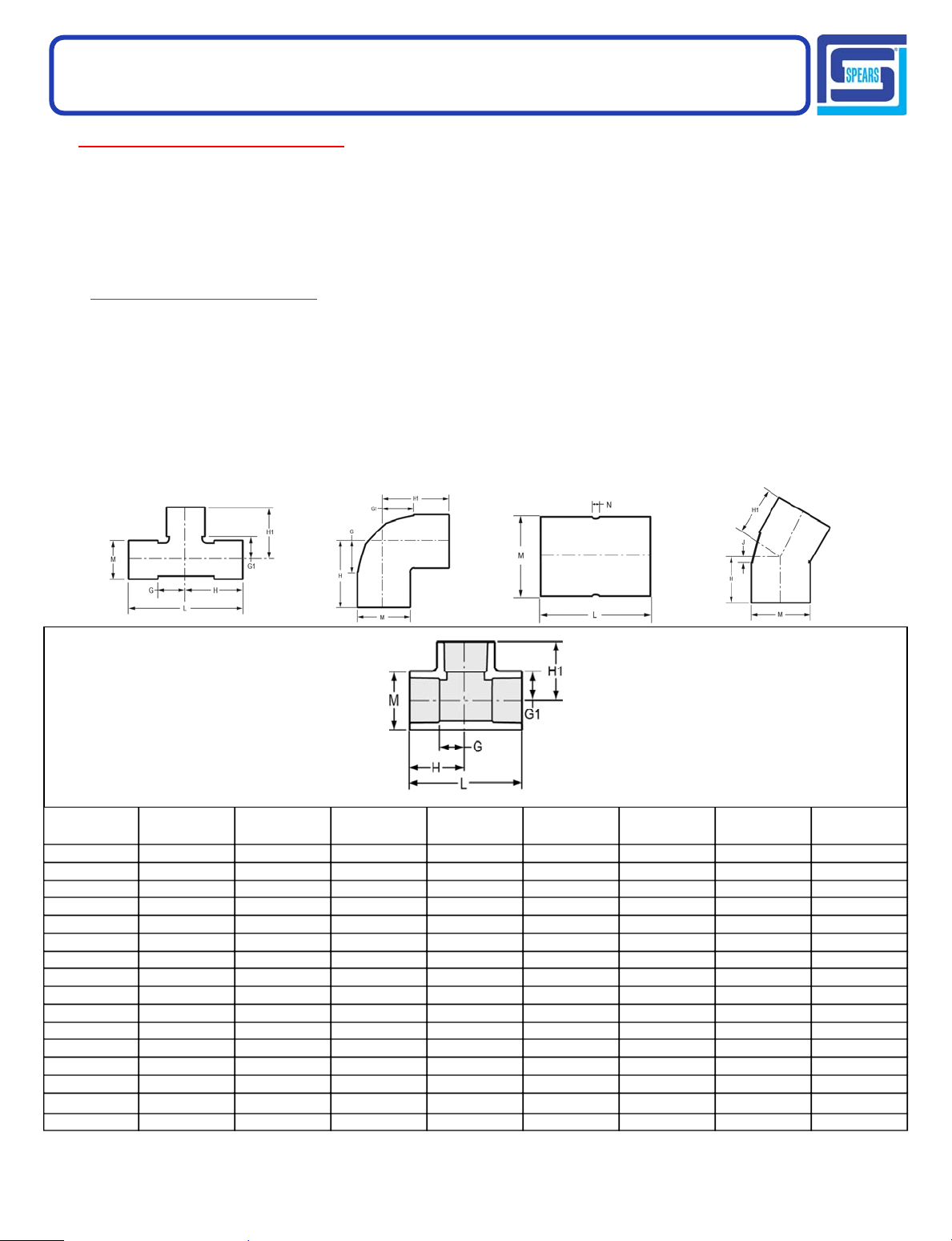
Injection Molded Dimension References:
G= (LAYING LENGTH) Intersection of center lines to bottom of
socket/thread; 90° elbows, tees, crosses; ± 1/32 inch.
H= Intersection of center lines to face of fitting; 90° elbows tees,
crosses; ± 1/32 inch.
J= Intersection of center lines to bottom of socket/thread; 45°
elbows; ± 1/32 inch
Fabricated Dimension References:
G= (LAYING LENGTH) Intersection of center lines to bottomof
socket/thread; 90° elbows, tees, crosses; ± 1/4 inch; 14" &
larger ± 1/2 inch.
H = Intersection of center lines to face of fitting; 90° elbows ± 1/4
inch, 14" & larger ± 3/4 inch; wyes ± 1/2 inch; tees, crosses
± 1/4 inch; 14" larger ± 1/2 inch.
J= Intersection of center lines to bottom of socket/thread;45°
elbows; ± 1/4 inch; 14" & larger ± 1/2 inch.
Typical Fabricated Dimension References
L= Overall length of fittings; ± 1/16 inch.
M= Outside diameter of socket/thread hub; ± 1/16 inch.
N= Socket bottom to socket bottom; couplings; ± 1/16 inch.
W= Height of cap; ± 1/16 inch.
L= Overall length of fittings; ± 1/2 inch.; wyes ± 1 inch; 14" &
larger ± 1 inch.
M= Outside diameter of socket/thread hub; ± 1/4 inch.
N= Socket bottom to socket bottom; couplings; ± 1/2 inch.
W= Height of cap; ± 1/4 inch.
Tee
Socket x Socket x Socket
Part Number Size G G1 H H1 L M
401-003 3/8 3/8 3/8 1- 1/8 1- 1/8 2- 1/4 31/32 .03
401-005 1/2 1/2 1/2 1- 1/4 1- 1/4 2- 1/2 1- 3/32 .06
401-007 3/4 9/16 9/16 1- 9/16 1- 9/16 3- 1/8 1- 5/16 .09
401-010 1 11/16 11/16 1- 3/4 1- 3/4 3- 1/2 1- 5/8 .15
401-012 1-1/4 7/8 7/8 2- 1/8 2- 1/8 4- 1/4 2 .25
401-015 1-1/2 1-1/8 1-1/8 2-3/8 2-3/8 4-3/4 2- 1/4 .33
401-020 2 1- 3/8 1- 3/8 2- 3/4 2- 3/4 5- 1/2 2- 3/4 .50
401-025 2-1/2 1-21/32 1-21/32 3-13/32 3-13/32 6-13/16 3-11/32 .96
401-030 3 1-15/16 1-15/16 3-27/32 3-27/32 7-11/16 4 1.44
401-040 4 2-13/32 2-13/32 4- 7/16 4- 7/16 8- 7/8 5- 1/32 2.34
401-050 5 3 3 6 6 12 6- 5/32 4.58
401-060 6 3- 5/8 3- 5/8 6-21/32 6-21/32 13- 5/16 7- 9/32 5.89
401-080 8 4- 1/2 4- 1/2 8-17/32 8-17/32 17- 1/16 9- 3/8 11.57
401-100 10 5-13/16 5-13/16 10-27/32 10-27/32 21-11/16 11-21/32 24.00
401-100F
*
401-120 12 6-27/32 6-27/32 12-27/32 12-27/32 25-11/16 13- 3/4 37.29
10 9- 7/8 9- 3/8 15- 1/8 14- 5/8 30- 1/4 11- 1/2 36.41
Approx. Wt.
(Lbs.)
Made in the U.S.A
Suitable for Oil-Free air handling to 25 psi, not for distribution of compressed air or gas
See Spears® Product Sourcebook for product offerings
Page 8
Page 2

Schedule 40 Fittings Technical
.
Schedule 40 Fittings Dimensions & Information
30° Ell
Socket x Socket
Part Number Size H J M
* Fabricated
415-120F
415-140F
415-160F
415-180F
415-200F
415-240F
*
*
*
*
*
*
12 9 2-3/4 13-9/16 16.57
14 10-5/16 3-5/16 14- 7/8 23.88
16 11-13/16 3-13/16 17 34.14
18 13-3/8 4-3/8 19- 1/8 49.74
20 14-15/16 4-15/16 21-3/16 64.48
24 18 6 25-3/8 109.36
22-1/2° Ell
Socket x Socket
(Continued)
Approx. Wt.
(Lbs.)
Part Number Size H J M
Approx. Wt.
416-005 1/2 1- 1/16 3/16 1- 5/32 .05
416-007 3/4 1- 3/16 3/16 1- 7/16 .16
416-010 1 1- 3/8 9/32 1-23/32 .26
416-012 1-1/4 1- 1/2 11/32 2- 3/32 .21
416-015 1-1/2 1-21/32 9/32 2-11/32 .25
416-015F
*
1-1/2 2-1/8 5/8 2-3/16 .22
416-020 2 1-23/32 3/8 2-23/32 .24
416-025 2-1/2 2- 1/4 1/2 3- 1/2 .69
416-025F
*
2-1/2 2-13/16 13/16 3- 1/4 .66
416-030 3 2-13/32 9/16 4- 5/32 .98
416-040 4 2-27/32 19/32 5- 3/16 1.68
416-045F
416-050F
*
*
4-1/2 3- 9/16 1- 1/16 5- 7/16 1.58
5 4- 1/8 1- 1/8 6- 1/16 2.11
416-060 6 4- 9/16 1- 9/32 7- 3/16 4.39
416-060F
*
6 4- 5/8 1- 3/8 7- 3/16 3.24
416-080 8 5- 7/8 1- 3/4 9- 3/4 8.3 8
416-080F
416-100F
416-120F
416-140F
416-160F
416-180F
*
*
*
*
*
*
8 12-11/16 3-11/16 9-1/8 5.72
10 7-5/16 2-1/16 11- 1/2 10.04
12 8- 1/2 2- 1/4 13- 9/16 14.91
14 9-3/4 2-3/4 14-7/8 20.77
16 11- 1/4 3- 1/4 17 30.96
18 12-11/16 3-11/16 19-1/8 46.31
(Lbs.)
Made in the U.S.A
Suitable for Oil-Free air handling to 25 psi, not for distribution of compressed air or gas
See Spears® Product Sourcebook for product offerings
Page 30
 Loading...