


SpearheadSpearhead
SpearheadSpearhead
Spearhead
1
Q15S, Q18S & Q21S
Q15S, Q18S & Q21S
and 15/18/21 Park
St andard Flail Mower
Operator’s manual
& part s list
Fourth edition
June 2004
© Spearhead Machinery Limited 2004
IMPORTANT - The information contained in this manual is correct
at the time of publication. However, in the course of constant
development, changes in specification are inevitable. Should you
find the information given in this book different to the machine it
relates to please contact the “After Sales Department” for advice.
Please ensure that this manual is handed to the operator before
using the machine for the first time. The operator must fully
understand the contents of this manual before using the machine.
(If the machine is resold the Manual must be given to the new owner.)

SpearheadSpearhead
SpearheadSpearhead
Spearhead
Q15S, Q18S & Q21S
2
Important
The purchaser should ensure that this manual is handed to the operator
before using the machine for the first time and should be satisfied that the
operator fully understands the contents of this manual before being allowed to proceed. If the machine is resold the Operators Manual must be
given to the new owner.
Fill in the details below, you will find it useful to refer to when ordering
spare parts.
Spearhead Machinery Ltd
Green View ,
Salford Priors,
Evesham, Worcestershire
WR1 1 8SW
T el: 01789 491860Fax: 01789 778683
e-mail: enquiries@spearhead.uk.com
Vist our web site: www.spearhead.uk.com
Serial No.
Date of Delivery
Dealer’s address
T elephone No.

SpearheadSpearhead
SpearheadSpearhead
Spearhead
3
Q15S, Q18S & Q21S
Contents
Safety ..............................................................................................4
EC declaration.....................................................................................5
Introduction..........................................................................................6
Safety first ...........................................................................................6
Tractor requirements ...........................................................................6
Attaching to the tractor ........................................................................7
Setting up and adjustment...................................................................8
Front linkage mounting ........................................................................9
Operation ..........................................................................................10
Rotor care ......................................................................................... 11
Servicing and maintenance
Gearbox .....................................................................................12
Flail Rotor (daily)........................................................................ 12
Greasing ....................................................................................13
Regular ...................................................................................... 14
Skids..........................................................................................14
Storage ...................................................................................... 15
Servicing checklist .....................................................................15
T orque Settings..........................................................................16
Troubleshooting .........................................................................16
Servicing log ..............................................................................17
Warranty Conditions .................................................................. 18
Extended warranty .....................................................................19
Parts List
Main body Assembly ..................................................................22
Rotor and Roller Assembly ........................................................24
Headstock - Pre May 2000......................................................... 26
Headstock - Post May 2000 .......................................................28
P.T.O. Shaft Assembly ..............................................................30
Cross shaft Assembly ...............................................................32
Gearbox Assembly ....................................................................34
Stickers...................................................................................... 36

SpearheadSpearhead
SpearheadSpearhead
Spearhead
Q15S, Q18S & Q21S
4
! Never operate the machine with other people present, as it is possible for debris,
including stones, to be discharged from the front and rear of the flail hood.
! Always ensure all cab safety guards are in place and all tractor windows closed.
! Never allow an inexperienced person to operate the machine without supervision.
! Never allow children to play on or around the machine at any time.
! Never attempt any maintenance or adjustment without first disengaging the PTO,
lowering to the ground, stopping the tractor engine and applying the tractor parking
brake.
! Before leaving the tractor cab always ensure that the machine is firmly on the ground,
and the rotor has stopped spinning.
! Never stop the engine with the PTO engaged.
! Always check that all guards are properly fitted, check there are no damaged or loose
parts. Particular attention should be given to the flails to ensure they are not
damaged, cracked or missing.
! Never operate with flails missing.
! Always operate PTO at recommended speed, 540 r.p.m.
! Always inspect work area for wire, steel posts, large stones and other dangerous
materials and remove before starting work.
! Never operate with wire around the rotor. Stop immediately .
! Never attempt to use the machine for any purpose other than that it was designed for .
! Ensure that all warning labels are always visible and that they are not damaged,
defaced or missing.
! Never transport with the PTO engaged.
! When parking up always lower to the ground.
Safety

SpearheadSpearhead
SpearheadSpearhead
Spearhead
5
Q15S, Q18S & Q21S
EC declaration of conformity, conforming to EEC
directive 89/392/EEC
We, S pearhead Machinery Lt d, Greem V iew, Salford Priors, Evesham,
Worcestershire WR11 8SW declare under our sole responsibility that the
product
product code
serial no. & date
type
.........................................................................
.........................................................................
.........................................................................
.........................................................................
Manufactured by the above company complies with the required
provisions of the directive 89/392/EEC, and AMD 91/368/EEC, AMD 93/44/
EEC, AMD 93/68/EEC and conforms with European norm. BSEN 292;
Part 1: 1991 safety of machinery - Terminology, methodology; Part 2; 1991
Safety of machinery - Technical specifications and other national
standards associated with its design and constructions as listed in the
T echnical File.
Signed
Status
Date
.........................................................................
on behalf of Spearhead Machinery Ltd
.........................................................................
.........................................................................

SpearheadSpearhead
SpearheadSpearhead
Spearhead
Q15S, Q18S & Q21S
6
Introduction
The Spearhead Q15S, Q18S and Q21S are robust high capacity flail mowers that are
easy to operate and maintain, but to ensure trouble-free operation this manual should be
carefully studied.
Safety First
Do not start the machine until you fully understand operation and safety precaution
requirements.
Tractor requirements
! Spearhead strongly recommend using a 25 - 50hp tractor with CATEGORY 1 rear
linkage.
! Minimum tractor weight including ballast must be 2500kg.
! PTO must be independent live drive to enable continuous PTO drive even when
tractor clutch is pressed down.
! Before hitching, ensure position control is selected. Do not attempt to hitch in draft
control.
! Check chains and stabilisers must be in good working order to hold the machine
firmly . Do not operate with out checking that chains and st abilisers are tight.
! Spearhead particularly recommend ‘turn buckle’ type check chains.
! Set linkage lift rods to an equal length.

SpearheadSpearhead
SpearheadSpearhead
Spearhead
7
Q15S, Q18S & Q21S
Attaching to the tractor
Fit the machine to the tractor linkage in the standard way , ensuring the correct match of linkage
(CAT 1 pins). Check that the top link is in good order and threads are well lubricated, (as fine
adjustment to height of cut is regulated by the top link). Use stabilisers to take any free movement
out of lower link arms. Before fitting the machine to the tractor linkage you should ensure there is
sufficient front weight to ensure the front wheels are always in contact with the ground. This is
most important for safe transport and stability when turning on slopes.
Before fitting the PTO for the first time, it may be necessary to adjust the length. There should be
maximum engagement of the sliding tubes without bottoming at the shortest operation position. To
check, first connect the mower to the tractor. Pull the PTO shaft apart and connect to the tractor
PTO output shaft and the gearbox input shaft. Hold the half shafts next to each other in the shortest
working position.
If necessary, shorten the inner and outer guard tubes equally (Fig. 2). Shorten the inner and outer
sliding profiles by the same length as the guard tubes. File all sharp edges and remove burrs.
Grease sliding profiles.
To fit the PTO, first clean and grease. Press
pins on the yoke and simultaneously push
the PTO drive shaft on to PTO shaft of the
tractor until pins engage.
The PTO shaft is fitted with a non-rotating
safety guard. It should be secured to the
machine and tractor with the two retaining
chains provided.
Fig. 2
Warning
Fully tighten check chains and linkage stabilisers to hold the machine rigid. There
must be no side ways movement, it is dangerous

SpearheadSpearhead
SpearheadSpearhead
Spearhead
Q15S, Q18S & Q21S
8
Setting up and Adjustment
Height adjustment
To achieve major adjustment to height of cut; reposition the two side plates attached to the
rear roller. A finer adjustment to cut can be achieved by lengthening or shortening the top
link of the tractor (Fig. 3).
Mechanical Offset - The linkage ‘A’ frame (Fig. 4) can be slid along the tube to
obtain numerous settings from central to fully offset by simply slackening the clamping
bolts, position the ‘A’ frame and re-tighten the bolts. Remember to regularly check that
these bolts are tight.
Adjusting height of roller
Fig. 3
Fig. 4

SpearheadSpearhead
SpearheadSpearhead
Spearhead
9
Q15S, Q18S & Q21S
Front linkage mounting
Simply remove the clamping bolts and revolve the ‘A’ frame through 180 degrees so the
linkage mounting pins are facing the rear of the mower. It is recommended the slotted
hole in the top link bracket is used when mounting onto the front linkage, this allows the
front of the mower to float over obstacles more easily.
The tractor front PTO has no standard rotation so it may be necessary to rotate the
gearbox through 180 degrees, to compensate for this irregularity. For most conditions it
is important the rotor rotates as indicated in Fig. 5a.
540 or 1000 rpm
If the tractor has only 1000 rpm. PTO output speed, it is possible to compensate by
swapping the top drive pulley on to the rotor and rotor pulley to the top drive shaft i.e.
smaller pulley driving the larger pulley will act as a reducer (Fig. 5b). Never operate the
PTO at 1000 rpm with the larger pulley driving the smaller rotor pulley. This will
drive the rotor at higher speed and will result in severe damage to the machine.
Fig. 5a - position of pulleys for 540r.p.m.
Fig. 5b - position of pulleys for 1000r.p.m.
a Rotation anti-clockwise
b Shaft pulley 150mm
c Shaft pulley 200mm
540r.p.m. 1000r.p.m.

SpearheadSpearhead
SpearheadSpearhead
Spearhead
Q15S, Q18S & Q21S
10
Operation
Engage the PTO only when the tractor engine is at low revs to prevent shock damage
to machine. Slowly increase the engine revs to achieve the standard 540 rpm PTO
speed. If at any time serious vibration occurs, stop the engine immediately and
check that no flails are missing, (following all safety precautions). The cause must
be found and rectified immediately or other components may be affected.
When in work, lower the machine to the ground carrying all its weight on the rear roller ,
allowing the machine to follow the contours of the ground. Select a sensible forward
speed bearing in mind the density of growth, the terrain, and the available horsepower,
taking extra care when turning, particularly on slopes. When turning it is not necessary
to lift the
machine
off the ground but instead allow sufficient room to turn in a large
radius. The machine only needs to be raised when turning a tight corner, or reversing
over dense undergrowth.
Quality of finish is determined by the forward speed i.e. a slow speed will produce a
high quality of cut, whereas faster forward speeds are used when high output is first
priority.
When cutting in extreme conditions or when small stumps, stones and other such solid
objects are likely to be found it is recommended the operator reduces the engine revs
to allow the flails to pivot more easily when striking solid objects, and procede with
caution.

SpearheadSpearhead
SpearheadSpearhead
Spearhead
11
Q15S, Q18S & Q21S
Remember, the rotor is highly complex andexpensive to manufacture, please treat with
care and enjoy the benefits of the Spearhead Rotor.
Rotor Care
Always inspect the condition of flails and bolts on a very regular basis.
Always replace bolts and nuts when replacing flails.
Always use genuine flails, bolts and nuts. The flails and bolts are made to a very high
standard from a high tensile steel, being fully heat treated and subjected to
rigorous testing in very stringent conditions to comply with our rigid quality
control requirements.
Never operate with bolts loose or flails missing.
Never change to a different spec or type of flail, this will immediately put the rotor out of
balance.
Never engage rotor at high PTO speeds.
Warning
Rotor is balanced to be run at PTO speed, do not operate above or below
this speed.
Warning
Never carry out any servicing or maintenance work without first
disengaging the PTO and stopping the tractor.

SpearheadSpearhead
SpearheadSpearhead
Spearhead
Q15S, Q18S & Q21S
12
Servicing and maintenance
Gearbox
! Before first use check gearbox oil level, thereafter check every 8hours.
! After the first 50 hours drain and replace the gearbox oil, thereafter
annually . Replace with EP90.
! Regularly inspect gearbox seals. If oil is leaking replace immediately .
This is your responsibility to maintain a long and reliable working life.
! Check that gearbox bolts are fully tightened.
Warning
Check that all gearbox bolts are tight. When the machine is new there will
be a ‘bedding in’ period when very frequent checking is important.
Warning
It is imperative the grubscrews are checked on the taper locks (once bedded in, loctite glue may prove useful).
Warning
Never carry out any servicing or maintenance work without first disengaging the PTO and stopping the tractor..
Flail Rotor (daily)
! Grease all bearings daily .
! Check there is no wrapping of string, plastic, grass or other debris on rotor shaft and rear
roller bearing.
! Check the condition of flails and ensure all retaining bolts are tight. When flails are re
placed, care must be taken to maintain balance of the rotor shaft, do not change to a
different type.
! Check flail retaining bolt and nut for tightness
! Never operate with any flails missing. This will cause severe vibration and lead to rapid
bearing wear and quickly cause the hood to crack. Cont’d
"
SpearheadSpearhead
SpearheadSpearhead
Spearhead
13
Q15S, Q18S & Q21S
! Blunt flails leave an untidy finish and absorb excessive power, when re-sharpening
always wear protective clothing and goggles.
! When flails are showing severe wear, damage or cracking, they must be replaced
immediately . Never attempt to weld the flails as this will make them very brittle, thus
extremely dangerous. Do not take risks with the cutting flails, if in doubt replace.
! When replacing flails always replace bolts and nuts for new.
! Regularly check that all rotor bearing bolts are tight.
! It is imperative the grubscrews are checked on the taper locks (once bedded in loctite
glue may prove useful).
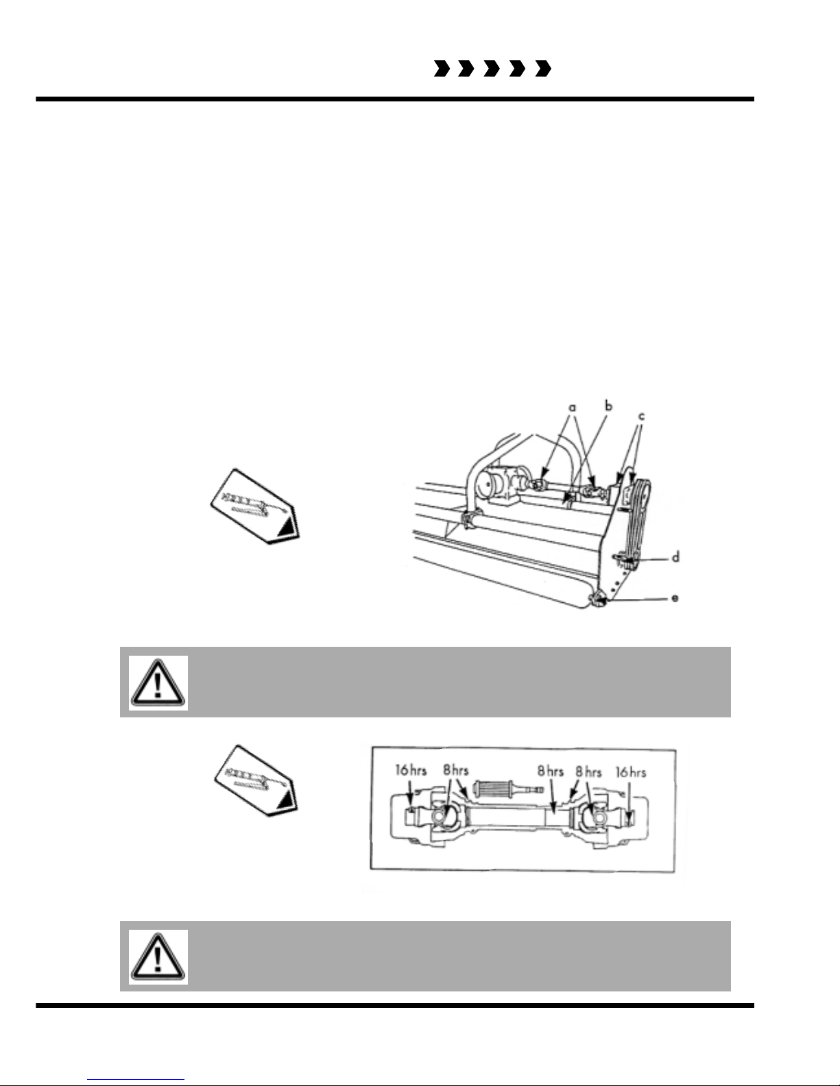
Greasing
Daily grease all points shown below.
Fig 7
PTO greasing points.
Warning
Grease rotor bearing and rear roller at least every 8 hours and especially
after washing.
Warning
Dismantle and clean PTO sliding surfaces and re-grease universal joints.
Fig. 6
Grease points for rotor , cross shaft and rear roller bearings.

SpearheadSpearhead
SpearheadSpearhead
Spearhead
Q15S, Q18S & Q21S
14
Regular
! Check the condition of drive belts, ensuring they are aligned and properly tensioned to
avoid any unnecessary belt wear.
! Remove both guards for access when tensioning belts, ensure belts are running in
line after adjustment.
! Check there is no wrapping of string, plastic, grass or other debris on rear roller.
N.B.
The pulleys are fitted with taper locks which have 7 screws to tighten, and 3 holes to aid
removal in the pulley centres.
Fig. 8
Tensioning drive belts
Skids
When operating on abrasive soils, particularly in stubbles and similar conditions with thin
ground cover, excessive skid wear may be expected. To provide extra protection and to
prolong life of the skids, special hard facing rods can be used.

SpearheadSpearhead
SpearheadSpearhead
Spearhead
15
Q15S, Q18S & Q21S
Storage
At the end of the season before storing, thoroughly wash the machine off, removing all traces of
grass and dirt. Great care must be taken when washing with high pressure hoses, do not hold the
water jet close to the paintwork. Use steam cleaners with caution and be sure to remove all
detergents to avoid any discolouring or damage to paint. Grease all grease points until fresh
grease shows. Store PTO shaft and drive belts in a dry place.
Servicing checklist (see relevant sections for full details)
Regularly Gearbox: Inspect seals, check bolts for tightness.
Flail rotor: check bolts for tightness, check condition of flails,
check retaining bolts for tightness, check rotor bearing bolts for
tightness.
Daily Maintain correct belt tension.
Check gearbox oil level.
Grease PTO shaft.
Grease all points as shown in diagram.
Every year Drain and replace gearbox oil with EP90.

SpearheadSpearhead
SpearheadSpearhead
Spearhead
Q15S, Q18S & Q21S
16
Problem Caus e Solution
Oil leve l incor rect Check oil level
Oil grade incorrect Check oil grade
Implement overloaded Reduce forward speed
Wrong p. t.o. speed
En sur e tr acto r p.t.o. spee d
matches implement
Belt an d Pulley condit ion Repla ce if ne cessary
Pulley Alignment Check Alignm ent
Incorrect Belt tension Tension belts to sp e c.
Overloading of Implem ent
Reduce forward speed or
increas e height of cut
Wo rking angle too great Red uce offset of implement
Shaft inco rrect length i.e.
bottoming out
R e size p .t.o. shaft as
recommended
Lack of maintenance
Grease p.t.o. shaft as
recommended
Flails worn Replace worn flails
Rotor speed/Direction Check tractor p.t.o. speed
Crop condition Look for suitable conditions
Rotor out of balance See rotor vibration
Wire/st ring in bearing Repla ce bearings
Lack of maintenance Re-balance/replace rotor
Water in bearing Remove debris
Rotor be ar ing failure
Gearbox Overheating
Exce ssive Belt W ear
P.t.o . wear UJ failure
Cut quality
Note:
When operating in arduous conditions with a tractor of more than 80hp, you can reduce the strain
on the drive line by:
a) Running with 1000 speed setup
b) Keeping the PTO shaft straight.
Troubleshooting
Size: Tensile strength: Description: Torque setting:
Nm.
M8 12.9 Pulley clamps 45
M10 8.8 General fasteners 65
M12 8.8 General fasteners 114
M16 8.8 Roller plate bolts 280
M14 10.9 Flail bolts 200
M24 8.8 Head stock bolts 950
Wheel nuts 270
Torque Settings
The torque figures given are recommended maximum settings only

SpearheadSpearhead
SpearheadSpearhead
Spearhead
17
Q15S, Q18S & Q21S
Servicing Log
Date..................................... Details ..................................................................................
...........................................................................................................................................
...........................................................................................................................................
...........................................................................................................................................
Date..................................... Details ..................................................................................
.............................................................................................................................................
.............................................................................................................................................

SpearheadSpearhead
SpearheadSpearhead
Spearhead
Q15S, Q18S & Q21S
18
The Spearhead Warranty
Spearhead warrant s that the Spearhead machine referred to in the W arranty Registration Form will
be free from defects in materials and workmanship for a period of 12 months from the date of sale.
This warranty does not affect your statutory rights, but merely adds to them. Should you have a
problem within 12 months from the date of sale please contact your original Spearhead dealer , or
Spearhead’ s Service Department. Any part found to be defective during this period will be replaced
or repaired, at Spearhead’ s discretion, by the dealer or a Spearhead Service Engineer .
Spearhead Warranty Conditions
1 The Warranty Registration Form must be completed and returned to S pearhead within 30
days of the date of sale.
2 This warranty does not cover defects arising from fair wear and tear , wilful damage,
negligence, misuse, abnormal working conditions, use in competition, failure to follow
Spearhead’s instructions (oral or written, including all instructions and recommendation
made in the Operator’s Manual) or alteration or repair of the machinery without Spearhead’s
approval.
3 The machinery must have been serviced in accordance with the Operator’s Manual and the
Service Log must have been kept up to date and made available to the dealer should
service, repair or warranty work be undertaken.
4 This warranty does not cover claims in respect of wearing parts such as blades, flails,
paintwork, tyres, belts, hydraulic hoses, bearings, bushes, linkage pins, top links, ball ends
unless there is a manufacturing or material defect or the cost of normal servicing items such
as oils and lubricants.
5 This warranty does not cover any expenses or losses incurred whilst the machinery is out of
use for warranty repairs or parts replacement.
6 This warranty does not extend to parts, materials or equipment not manufactured by
Spearhead, for which the Buyer shall only be entitled to the benefit of any such warranty or
guarantee given by the manufacturer to Spearhead. Only genuine S pearhead replacement
parts will be allowable for warranty claims.
7 All parts replaced by S pearhead under warranty become the property of Spearhead and
must be returned to Spearhead if S pearhead so request. Such parts may only be disposed
of after a warranty claim has been accepted and processed by Spearhead.
8 Spearhead is not liable under this warranty for any rep airs carried out without Spearhead’s
written consent or without Spearhead being af forded a reasonable opportunity to inspect the
machinery the subject of the warranty claim. Spearhead’ s written consent must, therefore,
be obtained before any repairs are carried out or parts replaced. Use of non-S pearhead
parts automatically invalidates the S pearhead Warranty . Failed components must not be
dismantled except as specifically authorised by Spearhead and dismantling of any
components without authorisation from Spearhead will invalidate this warranty .
9 All warranty claims must be submitted to Spearhead on S pearhead W arranty Claim Forms
within 30 days of completion of warranty work.
Using the machine implies the knowledge and acceptance of these instructions and
the limitations contained in this Manual.

SpearheadSpearhead
SpearheadSpearhead
Spearhead
19
Q15S, Q18S & Q21S
Extended Warranty
As an extension to the 12 month warranty set out above, Spearhead will provide an additional 12
month warranty cover subject to the Spearhead W arranty Conditions above and the Extended
Warranty Conditions below .
Extended Warranty Conditions
1 The extended warranty applies to hydraulic pumps, motors, valves and gearboxes only . It
does not apply to other parts, to consumables such as lubricants, seals or filters or to
labour charges.
2 The machinery must have had an annual service carried out by an Authorised S pearhead
Dealer or a Spearhead Service Engineer within 1 month of the first anniversary of the date
of sale and the Service Report form must have been completed and stamped by the
servicing dealer or Spearhead Service Engineer and sent to S pearhead within 14 days after
the first annual service.
3 The extended warranty does not cover costs of transportation of the machinery to or from
the dealer or Spearhead or the call out costs or travelling expenses of on-site visit s.
Transfer of W arranty
The Spearhead warranty may be transferred to a subsequent owner of the machinery (for use within
the UK) for the balance of the warranty period subject to all of the warranty conditions and provided
that the Change of Owner form is completed and sent to Spearhead within 14 days of change of
ownership.
Spearhead reserves the right to make alterations and improvements to any machinery
without notification and without obligation to do so.

SpearheadSpearhead
SpearheadSpearhead
Spearhead
Q15S, Q18S & Q21S
20

SpearheadSpearhead
SpearheadSpearhead
Spearhead
21
Q15S, Q18S & Q21S
Q15, Q18S & Q21S
Standard Flail Mower
Parts list

SpearheadSpearhead
SpearheadSpearhead
Spearhead
Q15S, Q18S & Q21S
22
Main Body Assembly

SpearheadSpearhead
SpearheadSpearhead
Spearhead
23
Q15S, Q18S & Q21S
Main Body Assembly
Ref. No Part No. English Description French Description German Description Danish Description
Réfé Numéro de Dési
g
nation en Anglais Désignation en Français Désignation en Allemand Désignation en Danois
Ref. No Teilenummer En
g
lische beschreibun
g
Französische beschreibungDeutsche beschreibun
g
Dänische beschreibun
g
Ref. No Reservedelsnu Engelsk beskrivelse Fransk beskrivelse Tysk beskrivelse Dansk beskrivelse
1771532 1.5m Main body Caisse Körper Krop
1771538 1.8m Main body Caisse Körper Krop
1771584B 2.1m Main body Caisse Körper Krop
1771584C
2.1m body (Post ser. No.
10312444526)
Caisse Körper Krop
2 5770010 Gearbox Multiplicateur Getriebekasten Gearkasse
3 4770860EC Bearing EC collar Douille Klemmring Klemring
4 1771513 Bracket Support - Étrier Konsole Konsol
5 1771520 Bearing bracket Support - Étrier Konsole Konsol
6 4770926 Pulley Poulie Riemenscheibe Remskive
7 4770927 Pulley Poulie Riemenscheibe Remskive
8 4770922 Clamping element Palier - Roulement Lager Leje
9 4770923 Clamping element Palier - Roulement Lager Leje
10 4770870 Drive belt Caoutchouc Gummi Gummi
11 1772211 Layshaft Arbre Welle Aksel
12 4772229 Key Clavette Nut Not
5770066 Cross shaft Arbre Welle Aksel
5770115
Cross shaft - post serial
no. 1031421392
Arbre Welle Aksel
14 2770436 Flat washer Rondelle Spannscheibe Spændeskive
15 2770419 Bolt Boulon Bolzen Bolt
16 2770417 Nut Écrou Mutter Møtrik
17 2770443 Bolt Boulon Bolzen Bolt
18 2770442 Spring washer Rondelle Spannscheibe Spændeskive
1771511A Shaft guard Protecteur Schutz / Deckel Beskyttelse / Dæksel
1771511L
Shaft guard - post serial
no. 1031421392
Protecteur Schutz / Deckel Beskyttelse / Dæksel
21 2770469 Spring washer Rondelle Spannscheibe Spændeskive
22 2770396 Bolt Boulon Bolzen Bolt
23 2770535 Bolt Boulon Bolzen Bolt
24 2770536 Full nut Écrou Mutter Møtrik
25 2770393 Bolt Boulon Bolzen Bolt
8550130 Rubber flap 1.5m Caoutchouc Gummi Gummi
8400205 Rubber flap 1.8m Caoutchouc Gummi Gummi
8400209 Rubber flap 2.1m Caoutchouc Gummi Gummi
27 5770107 Cone Protecteur Schutz / Deckel Beskyttelse / Dæksel
1771514A Belt guard Protecteur Schutz / Deckel Beskyttelse / Dæksel
1771514B
Belt guard - Post serial
No. 1031221394
Protecteur Schutz / Deckel Beskyttelse / Dæksel
1771534 Retaining strip 1.5m Caoutchouc Gummi Gummi
1771531 Retaining strip 1.8m Caoutchouc Gummi Gummi
1771572 Retaining strip 2.1m Caoutchouc Gummi Gummi
31 2770418 Bolt Boulon Bolzen Bolt
32 1771530 Skid Construction Fabrikationsteil Fabrikatiensdel
33 2770458 Bolt Boulon Bolzen Bolt
34 2770381 Bolt Boulon Bolzen Bolt
41 8777516 End cap Protecteur Schutz / Deckel Beskyttelse / Dæksel
28
1
26
30
19
13

SpearheadSpearhead
SpearheadSpearhead
Spearhead
Q15S, Q18S & Q21S
24
Rotor and Roller Assembly
Rotor
Roller

SpearheadSpearhead
SpearheadSpearhead
Spearhead
25
Q15S, Q18S & Q21S
Rotor and Roller Assembly
Ref. No Part No. English Description French Description G erman Description Danish Description
Réfé Numéro de Désignation en Anglais Désignation en F r ançais Désignation en Al lemand Dés ignation en Danoi s
Ref. No Teil enummer En
g
li sche beschreibungFranzösische Deutsche beschreibungDäni sche bes chreibun
g
Ref. No Reservedelsn Engelsk beskrivelse Fransk beskrivelse Tysk beskrivelse Dansk beskrivelse
SA00092 1.5m rotor assembly Rotor Rotor Rotor
SA00102 1.8m rotor assembly Rotor Rotor Rotor
SA00103 2.1m rotor assembly Rotor Rotor Rotor
2 7770715 Twist e d flail Fléau Schlegel Slagle
3 1777310 Beari n g housing Carter Gehäuse Hus
4 1771529 Housing Carter Gehäuse Hus
5 4770891 Rotor bearing Palier - Roulement Lager Leje
6 2771610 Circlip C irclip Sicherungsring Lasering
7 1777209 Retai n i n g washer Rondelle Spannscheibe Spændeskive
8 2770506 Bolt Boulon Bolzen Bolt
9 4771123 Seal Rondelle Spannscheibe Spændeskive
10 1777312 Rotor shaft cover Prot ecteur Schutz / Deckel Beskyttelse / Dæksel
11 2770467 Grease nipple Graisseur Schmiernippel Smørenippel
11a 2770497 G rease nipple Graisseur Schmierni ppel Smørenippel
12 2770436 Flat washer Rondelle Spannscheibe Spændeskive
13 2770443 Bolt Boulon Bolzen Bolt
14 2770397 Bolt Boulon Bolzen Bolt
15 2770417 Nut Écrou Mutter Møtrik
1
Rotor
Roller
Re f. No Part No. English Des cription French Description Ger m an Des cription Danish Description
Réfé Numéro de Désignation en Anglais Désignation en Français Désignation en Allemand Désignation en Danoi s
Ref. No Tei lenummer Englis c he Franz ösis che Deutsc he bes chrei bung D äni sche bes chreibung
Ref. No Reservedelsn Engelsk beskrivelse Fransk beskrivelse Tysk beskrivelse Dansk beskrivelse
1771533 Roller - 1.5m Rouleau Hinterlaufwalze Bagvalse
1771527 Roller - 1.8m Rouleau Hinterlaufwalze Bagvalse
1771582 Roller - 2.1m Rouleau Hinterlaufwalze Bagvalse
2 1777314 Stub shaft Arbre Well e Aksel
3 4771604 Rear roller bearing Palier - Roulement Lager Leje
4 2777519 Circlip Rondelle Spanns cheibe Spændeskive
5 2771108 Circ lip Bague - Anneau Ring Ring
6 1777231A Hub cover Protecteur Schut z / Deckel Beskyttelse / Dæksel
7 2770468 Grease nipple Graisseur Schmiernippel Smørenippel
1771526A Roller plate - LH Plaque Platte Plade
1771526AR Roller plate - RH Plaque Platte Plade
9 2770436 Fl at washer Rondelle Spannscheibe Spændeskive
10 2770397 Bolt Boulon Bolzen Bolt
2770397 Bolt Boulon Bolzen Bolt
2770259
Coach Bolt - Post
seria l No's
1040815199 (Q15S)
1041918308 (Q18S)
1042121442 (Q21S)
Boulon Bolzen Bolt
12 2770417 Nut Écrou Mutter Møtrik
Not illustrated
Sans gravure Nicht abgebildet Ikke illustreret
6770933 1.5m scraper wire ropeChaîne - chaînette Kette Kæde
6770932 1.8m scraper wire rop
e
Chaîne - chaînette Kette Kæde
1
8
11

SpearheadSpearhead
SpearheadSpearhead
Spearhead
Q15S, Q18S & Q21S
26
Headstock Assembly
Pre May 2000

SpearheadSpearhead
SpearheadSpearhead
Spearhead
27
Q15S, Q18S & Q21S
Ref. No Part No. English Description Fre nch Description German Description Danish Description
Réfé Numéro de Dési
g
nation en Anglais Désignation en Français Désignation en Al lemand Désignation en Danois
Ref. N o Teile nu mmer En
g
lisc he beschreibungFranzösische Deutsche beschreibungDäni sche beschreibun
g
Ref. No Reservedelsn Engelsk beskrivelse Fransk beskrivelse Tysk beskrivelse Dansk beskrivelse
1 1771524
Headstock - Pre May
2000
Poupée A-rahmen A-ramm e
2 1771503 Headstock clamp Bride de retenue Halter Holder
3 2770454 Flat washer Rondelle Spannscheibe Spændeskive
4 2770425 Bolt Boulon Bolzen Bolt
5 2770447 Nut Écrou Mutter Møtrik
6 1771525 L/H Lower link brkt Plaque Platte Pl ade
7 1771525R R/ H Lower link brkt Plaque Platte Plade
8 6310206 Lynch Pin Goupille B olzen Bolt
11 6310202 Cat 1Top link pin Goupille Bolzen Bolt
Headstock Assembly
Pre May 2000

SpearheadSpearhead
SpearheadSpearhead
Spearhead
Q15S, Q18S & Q21S
28
Headstock Assembly
Post May 2000

SpearheadSpearhead
SpearheadSpearhead
Spearhead
29
Q15S, Q18S & Q21S
Re f. No Part No. English Description French Description German Description Danish Description
Réfé Numéro de Dési
g
nation en Anglais Désignation en Français Désignation en Allemand Dés ignation en Danois
Ref. No Teilenummer En
g
lische beschreibungFranzösische Deutsche beschreibungDänische beschreibun
g
Ref. No Reservedelsn Engelsk beskrivelse Fransk beskrivelse Tysk beskrivelse Dansk beskrivelse
1 1 771524 A
He adst ock - Post M ay
2000
Poupée A-rahmen A-ram me
2 1771573 Headstock rear li nk Construction Fabrikat ionsteil Fabrikat iensdel
3 1771503A Headstock clamp Bride de retenue Halter Holder
4 2770517 F lat washer Rondelle Spannscheibe S pændeskiv e
5 2 770409 Nut Écrou Mutter Møtrik
6 8777516 End cap Bouchon Sc hr aube Prop
7 2770454 F lat washer Rondelle Spannscheibe S pændeskiv e
8 2770456 Spr ing washer Rondelle Spannscheibe Spændeskive
9 2 770425 Bolt Boulon Bolzen Bolt
10 6310229 Lower link pin Goupille Bolz en Bolt
11 6310202 Top link pin Goupille Bolz en Bolt
12 63 102 06 Pin Goupille Bolze n Bolt
13 2770549 Bolt Boulon Bolzen Bolt
Headstock Assembly
Post May 2000

SpearheadSpearhead
SpearheadSpearhead
Spearhead
Q15S, Q18S & Q21S
30
4
3
PTO Shaft Assembly
1
11
2
12

SpearheadSpearhead
SpearheadSpearhead
Spearhead
31
Q15S, Q18S & Q21S
PTO Shaft Assembly
R ef. No Part N o. E nglish Description French Description G erman D escription Da nish Description
Réfé Numéro de
p
ièce Désignation en Anglais Désignation en Français Désignation en Allemand Désignation en Danois
Ref. No Teilenummer En
g
lische beschreibungFranzösische beschreibungDeutsche beschreibungDänisch e be sch re ibun
g
Ref. No Reservedelsnum Engelsk beskriv e lse Fra n sk be skriv else Tysk beskrivelse Dansk be skriv e lse
5770069 P.t.o. shaft assembly Prise de froce Gelenkwelle Pto-aksel
1 5772259 Complete guard Protecteur Schutz / Deckel Beskyttelse / Dæksel
2 5771020 R etaining chain Chaîne - chaînette Kette Kæde
3 5770112 Y oke Joint (d'assemblage) Gelenkteil Gaf fel
4 5771023 Release button Levier Bedienungshebel Betjeningshåndtag
5 5770113 Cross journal
Portée d'arbre
transversale
Kreuzgarnitur Kardan k ryds
6 5772273 Inner tube y oke Joint (d'assemblage) Gelenkteil G affel
7 5772274 O uter tube y oke Joint (d'assemblage) Gelenkteil Gaffel
8 277 05 1 5 Ro ll p in G o u pille Bo lzen Bolt
9 5772270 O uter profile tube Tube Schlauch Slange
10 5772269 Inner profile tube Tube Schlauch Slange
11 5771336 Outer bearing Palier-Roulement Lager Leje
12 5771337 Inner bearing Palier-Roulement Lager Leje

SpearheadSpearhead
SpearheadSpearhead
Spearhead
Q15S, Q18S & Q21S
32
Cross Shaft Assembly

SpearheadSpearhead
SpearheadSpearhead
Spearhead
33
Q15S, Q18S & Q21S
Cross Shaft Assembly
Ref. Part No. English Description French Description German Description Danish Description
Réfé Numéro de pièce Désignation en Anglais Désignation en Français Désignation en Désignation en Danois
Ref. Teilenummer Englische beschreibung Französische Deutsche beschreibung Dänische beschreibung
Ref. Reservedelsnum Engelsk beskrivelse Fransk beskrivelse Tysk beskrivelse Dansk beskrivelse
1 5772279 6 Spline yoke Cannelure Nut Not
2 2770467 Gr ea se nipple Graisseur Sc hmiernippel Smørenippe l
3 5770113 Cross journal
Portée d'arbr e
transvers ale
Kreuzgarnitur Kardankryds
4 5772274 Tube y oke Tube Sc hlauch Slange
5 2770527 Pin Goupill e Bolzen Bolt
6 5772275
Outer profile tube 150mm
Tube Schlauch Slange
7 5772271 Clamp y oke - 35mm Bride de retenue Halter Holder
2770424 Bolt Boulon Bolzen Bolt
2770417 Ny loc nut Écrou M u t t e r Mø trik
2770436 Flat wa sher Rondelle Span nscheibe Spændeskiv e
8

SpearheadSpearhead
SpearheadSpearhead
Spearhead
Q15S, Q18S & Q21S
34
Gearbox Assembly
15
15
16
17
18
19
15

SpearheadSpearhead
SpearheadSpearhead
Spearhead
35
Q15S, Q18S & Q21S
Gearbox Assembly
Ref. No Part No. English Description French Description German Description Danish Description
Réfé Numéro de Désignation en Anglais Désignation en F rançais Désignation en Allemand Désignation en Danois
Ref. No Teilenumme
r
Englische beschreibungFranzösische Deutsche beschreibungDänische beschreibun
g
Ref. No Reser vedelsn Engelsk beskrivelse Fransk beskrivelse Tysk beskrivelse Dansk beskrivelse
1 N/A Casing Chässis Rahmen Ramme
2 5777201 Cover Protecteur Schutz / Deckel Beskyttelse / Dæksel
3 5 777203 Gasket Garnitu re Dichtung Pakning
4 2770402 Cover bolt Boulon Bolz en Bolt
5 N/A S haft Arbre Welle Aksel
6 4777205 Bearing Palier - Roulement Lager Leje
7 4771620 Bearing Palier - Roulement Lager Leje
8 4771506 Oi l seal Joint Öldichtung Pakning
9 4777201 Bearing Palier - Roulement Lager Leje
10 4771600 B ear ing Palier - Roulement Lager Leje
11 4771124 Oil seal Joint Öldic htung Pakning
12 N/A Gearwheel & pinon Vitesse Getriebe Gear
13 1777602 Rear shaft guard Protecteur Schutz / Deckel Beskyttelse / Dæksel
14 5777208 Plug Bouchon Schraube Prop
15 27711 29 Circlip Circlip Sicherungsring Las e ring
16 27711 08 Circlip Circlip Sicherungsring Las e ring
17 27711 07 Circlip Circlip Sicherungsring Las e ring
18 2770407 Bolt Boulon Bolzen Bolt
19 2770434 Washer
Rondelle Spanns cheibe Spændeskive

SpearheadSpearhead
SpearheadSpearhead
Spearhead
Q15S, Q18S & Q21S
36
123
45
6
7
Stickers Assembly

SpearheadSpearhead
SpearheadSpearhead
Spearhead
37
Q15S, Q18S & Q21S
Stickers Assembly
Ref. No Part No. English Description French Description German Description Danish Description
Réfé Numéro de Désignation en Anglais Désignation en Français D és ignation en Al lemand Désignation en Danois
Ref. N o Teile n u m m e r En
g
lisc he besc hreibungFranzösische Deutsche beschreibungDäni sche beschreibun
g
Ref. No Reservedelsn Engelsk beskrivelse Fransk beskrivelse Tysk beskrivelse Dansk beskrivelse
1 8770357
Keep safe distance
when machine is
running' Sticker
---
2 8770356
'Do not remove/open
guard' Sticker
---
3 8770358
'Shut off engine,
remove key' Sticker
---
4 8770360
' S tay clear of mower
flails' Stic k er
---
5 8770363 'Read manual' St i cker - - 6 8770306 'Keep bol t tight' Sticker - - 7 8770322 'Grease point' St icker - - -

SpearheadSpearhead
SpearheadSpearhead
Spearhead
Q15S, Q18S & Q21S
38
5
1
Stickers Assembly
4
3
2

SpearheadSpearhead
SpearheadSpearhead
Spearhead
39
Q15S, Q18S & Q21S
Stickers Assembly
R ef . No Part No. En glish Descriptio n French Descript ion German Description Danish Descript ion
Réfé Numéro de Désignation en Anglais Désignation en Français Désignation en Allemand Désignation en Danois
Ref. No Teilenummer En
g
lische beschreibungFranzösische Deutsche beschreibungDänische beschreibun
g
Ref. No Reserv edelsn Engelsk beskrivelse Fransk beskrivelse Tysk beskr ivelse Dansk beskrivelse
1 8770346
'Check - chains''
Sticker
---
2 8770307
'Manufactured in Gr eat
Britain' Sticker
---
3 8770340 'Read Manual' S ticker - - -
4 8770305
'Recommended PTO
speed 540 rpm' S t ic k er
---
5 8770341 'Belt t ension' S ticker - - -
 Loading...