

Page 1
®
SPEAKMAN
SM-5000
Installation, Operation & Maintenance Instructions
SENTINELPRO™ COMBINATION SERIES
DESCRIPTION
Speakman SentinelPro™ Combination, SM-5000, unites Anti-Scald Thermostatic / Pressure Balance
Shower/Bath Valve with integral Check Stops (CPV-TP) and Trim (CPT-5001).
SPECIFICATIONS
CPV-TP ANTI-SCALD THERMOSTATIC / PRESSURE BALANCE SHOWER VALVE:
CONNECTIONS: ½” Female Copper Sweat and ½” NPT Male at both the Inlets (Cold, Hot) & Outlets
(Shower, Tub)
FLOW RATE: 1.5 gpm (5.7 L/min) or higher
COMPLIANCE: ASSE 1016 / ASME A112.1016 / CSA B125.16 & ASME A112.18.1 / CSA B125.1 Standards
CPT-5001 T/P VALVE TRIM:
FINISH: Polished Chrome
COMPLIANCE: ASME A112.18.1 / CSA B125.1 Standard
INSTRUCTIONS
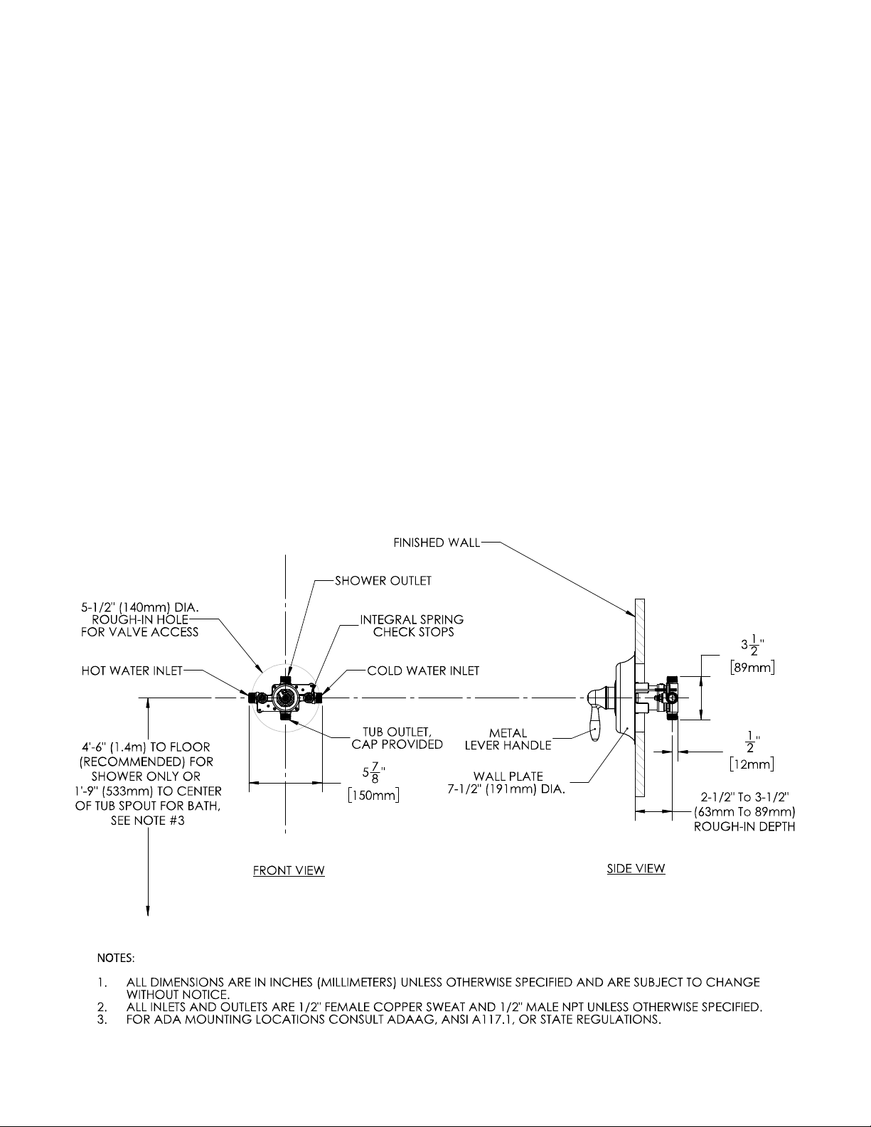
See individual products for installation of the components and warranty information.
ROUGH-IN
SPEAKMAN®
400 Anchor Mill Rd. New Castle, DE 19720 Phone: 800-537-2107 Fax: 800-977-2747
12/07/17 www.speakman.com 92-SM-5000-01
Page 2
INSTRUCTIONS FOR MODELS
92-CPV-TP-02
For additional assistance or service please contact:
SPEAKMAN
®
Company
400 Anchor Mill Road
New Castle, DE 19720
800-537-2107
www.speakman.com
CPV-TP
CPV-TP-DV
HELPFUL TOOLS & SUPPLIES:
TOOLS AND SUPPLIES
Pencil Keyhole
Saw
Adjustable
Wrench
Thread Seal
Tape
9/16”Deep Well
Socket
Socket
Wrench
Solder Kit
Phillips
Screwdriver
Measuring
Tape
Safety
Glasses
Tubing
Cutter
13/16”Deep Well
Socket
Level
Additional warranty information can be found at:
www.speakman.com
WARRANTY
Your new Shower/Bath Valve is designed for years of
trouble-free performance. Keep it looking new by
cleaning it periodically with a soft cloth. The use of
harsh chemicals and abrasives on any of the Speakman
custom finish products may damage the finish and void
the product warranty. Please be sure to only use
approved cleaners. Please contact Speakman for any
clarification of acceptable cleaners.
MAINTENANCE
Cover your drain to prevent loss of parts. Be sure to
wear eye protection while cutting pipe.
SAFETY TIPS
IMPORTANT
• Be sure to read instructions thoroughly before
beginning installation.
• Be sure to have properly adjusted the Temperature
Limiting Stop (TLS) as outlined in this Installation
Manual.
• Inspect all connections after installation of valve.
• This valve has an operating range of 20-80 Psi.
• This valve is designed to be used in conjunction
with a shower-head rated at 1.5 gpm (5.7 L/min)
or higher flow rate.
• NOTE: This installation manual covers several
models of valves. While the appearance of your
valve may differ from those shown, the installation
method is the same.
• Maximum water pressure: 125 PSI static; minimum
water pressure: 20 PSI flowing; minimum cold
supply temperature: 40° F; maximum hot supply
temperature: 160° F; minimum hot supply
temperature: 5° F above set point.
This type of valve must be cleaned and maintained on a
regular basis. Periodic maintenance should be
performed at least every 12 months or after any
changes have been made to the building’s plumbing
system. This maintenance should include removing and
cleaning the spring check stop components. Make sure
the stop poppet in each stop moves freely. The Lower
Cartridge Seal with Integral Screens (located at the base
of the Valve Cartridge) should be removed and cleaned
during this maintenance cycle.Valves that are installed
outdoors should be winterized by removing all of the
internal parts and removing any standing water from the
valve. Quarterly the maximum hot temperature setting
(TLS) should be checked and adjusted accordingly.
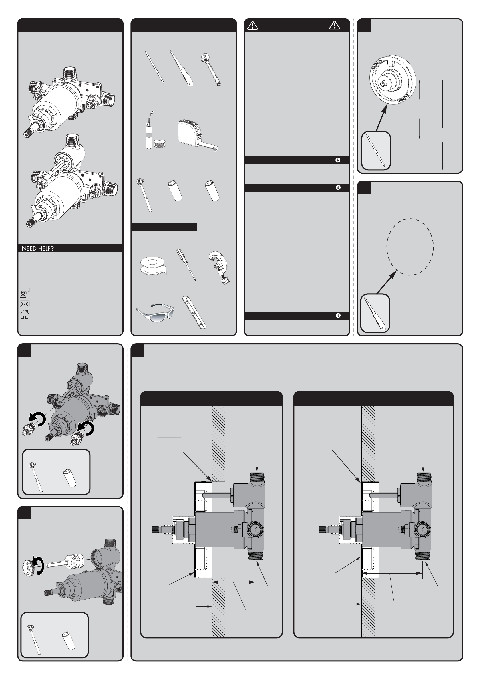
1
Referencing the supplied rough-in dimensions
(located at the end of this manual), determine the
preferred location of valve. Align the supplied
rough-in template with this location and trace
outline of template onto wall.
1’-9” (533mm)
TO CENTERLINE
OF TUB SPOUT
(FOR TUB INSTALLATION)
4’-6” (1.4m)
TO FLOOR
(SHOWER INSTALLATION)
2
Using a keyhole saw or similar tool, cut along
traced line and remove this section of wall.
3
Unthread and remove the Integral Stops using
a socket wrench equipped with a 9/16” deep
well socket.
Socket
Wrench
9/16”Deep Well
Socket
+
4
If your Shower Valve is equipped with an
integral diverter, remove the Diverter Nut using
a socket wrench and a 13/16” deep well
socket. Remove Diverter Cartridge to prevent
damage during soldering.
Socket
Wrench
+
13/16”Deep Well
Socket
5
Install the Rough-In Template over the Shower Valve being sure the Rough-In Template sits flush against Shower Valve Bonnet. Following the rough-in
dimensions for your model of valve (located ot the end of this manual) as well as the markings on the supplied rough-in template, install valve at proper
depth. The distance from the centerline of the inlet/outlet ports of the valve assembly to the finished wall MUST be between 2½” - 3½”. See images below
for reference.
SHOWER OUTLET
TUB OUTLET
ROUGH-IN TEMPLATE
THE BACK EDGE OF THE
ROUGH-IN TEMPLATE IS
FLUSH WITH OR INSIDE
THE VALVE ACCESS HOLE.
FINISHED WALL SURFACE
2½” MINIMUM
MOUNTING DEPTH
MINIMUM MOUNTING DEPTH
SHOWER OUTLET
TUB OUTLET
ROUGH-IN TEMPLATE
THE FRONT SURFACE OF
THE ROUGH-IN TEMPLATE
IS FLUSH WITH OR OUTSIDE
THE VALVE ACCESS HOLE.
FINISHED WALL SURFACE
3½” MAXIMUM
MOUNTING DEPTH
MAXIMUM MOUNTING DEPTH
Page 3
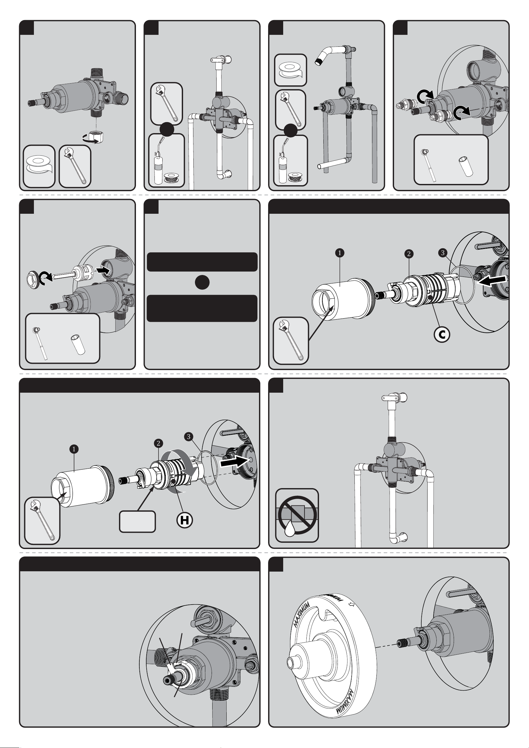
6
If your installation is for a shower only, apply
thread seal tape to the lower outlet port and
install the included cap. Wrench tighten.
7
Ensure Valve is positioned plumb and level.
Remove Rough-In Template from Valve. Make
threaded connections or plumb and solder all
joints and fittings. Take care to protect
surrounding area when soldering. Secure piping
to surrounding structure.
OR
8
Make piping connections for all accessories.
Take care to protect surrounding area when
soldering. Secure piping to surrounding
structure.
OR
9
Reinstall the Integral Stops using a Socket
Wrench equipped with a 9/16” Deep Well
Socket or Crescent Wrench.
Socket
Wrench
9/16”Deep Well
Socket
+
10
If your Shower Valve is equipped with an
integral diverter, reinstall the Diverter
Cartridge taking care to align mounting posts
of cartridge with the corresponding holes in
the diverter valve body. Install Diverter Nut
and tighten with a Socket Wrench and
13/16” Deep Well Socket. Take care to not
over-tighten connections.
Socket
Wrench
+
13/16”Deep Well
Socket
11
If you are performing a Standard
Installation, please proceed to Step 14
If you are performing a Back to Back
Installation, or have reversed inlet
supplies, please proceed to Step 12
Your Shower Valve has the ability to be mounted
back-to-back with another Valve in a shared
space. This means the hot and cold inlets may
be reversed. Please see the following steps to
adapt your valve for back-to-back mounting or
reversed inlet supplies.
OR
BACK-TO BACK INSTALLATION STEP 1
To adapt your shower valve for back to back installation, use an adjustable wrench to unthread and remove the Bonnet
❶. Then remove Cartridge Assembly ❷, and Bonnet O-Ring ❸ from valve body.
12
Rotate Valve Cartridge ❷180˚ and reinstall into Valve Body taking care to properly align the mounting posts of the
Cartridge with the corresponding holes within the Valve. The “H” marking on Valve Cartridge cover should now be on
the right hand side. Reinstall Bonnet ❶ , making sure the Large Bonnet O-Ring ❸ is in place within the Valve Body.
ROTATE
180˚
BACK TO BACK INSTALLATION STEP 213
14
Ensure the Valve is in the “OFF” position. Turn “ON” water supplies and check all connections for leaks.
The maximum hot water temperature setting adjustment (Temperature Limit Stop (TLS)) of the valve has
been factory set at 110° F. Important- Check each valve installation with a thermometer to make sure
the maximum hot water temperature is set to the recommended setting of 110° F maximum. To lower
the limit of the maximum hot water temperature the valve delivers, adjust the valve’s temperature limit
stop (TLS) plate.
• Slip the retaining O-ring and the TLS plate
towards the end of the spindle.
• With the water supplies on, rotate the
valve spindle clockwise to the maximum
desired hot water temperature.
• Position the TLS plate so it contacts the lug
and therefore restricts the clockwise rotation
of the spindle.
• Slip the retaining O-ring back into the
groove of the spindle to hold the TLS plate in
place.
• Rotate the spindle counter-clockwise to the
“Off” position.
TEMPERATURE LIMIT ADJUSTMENT
LUG
TLS PLATE
O-RING
15
16
Reinstall Rough-In Template over Valve to protect it during final wall preparation.
Page 4
CPV-TP / CPV-TP-DV SERVICE INSTRUCTIONS
Service instructions
Caution- Any repair or servicing of the valve may affect the maximum hot temperature setting of the valve. After
working on the valve, make sure the maximum hot water temperature is set to the recommended setting of 110° F
maximum.
T/P Cartridge Removal
1) Shut off the hot & cold water supply integral stops at the valve. Remove valve trim from valve.
2) With the valve in the OFF position, remove the Bonnet by unthreading with an adjustable wrench. The cartridge
may come out with the bonnet.
3) If necessary, remove the cartridge from the valve body by pulling on the valve spindle of the cartridge. Make
sure the lower cartridge seal is installed in the bottom of the cartridge and not in the valve body. Inspect Lower
Cartridge Seal with Integral Screens to verify they are debris free. If debris is present, remove Lower Cartridge Seal
and clean Screen material.
4) Replace the necessary parts with new parts. When replacing the T/P cartridge, make sure that the Lower
Cartridge Seal is properly installed in the recesses on the bottom of the cartridge. This Lower Cartridge Seal is
positioned over the hot & cold inlet holes inside the body.
5) Make sure the large bonnet O-ring seal is installed and seated properly in the valve body. Reassemble the valve
bonnet by threading it into the valve body with an adjustable wrench. Important- Adjust the valve’s maximum hot
water temperature to the recommended setting of 110° F. See Step #15 of the installation instructions for the TLS
adjustment instructions.
6) Turn ON the hot & cold water supply integral stops. Check valve for leaks.
7) Reassemble the valve trim parts.
Spring Check Stop Parts Removal
1) Shut off hot and cold water supply valves to the integral stops of the valve. Remove valve trim from valve.
2) CLOSE integral stops by turning the stop spindles clockwise. Unscrew the stop’s retaining nut with wrench.
Carefully remove the retaining nut w/spindle, spring, and poppet assembly. Clean and/or replace the necessary
parts. Reassemble the parts, reversing the above procedure. Repeat procedure on the other stop.
3) OPEN the integral stops by turning the stop spindles counter clockwise. Turn on the hot and cold water supply
valves. Check for leaks.
4) Reassemble the trim parts.
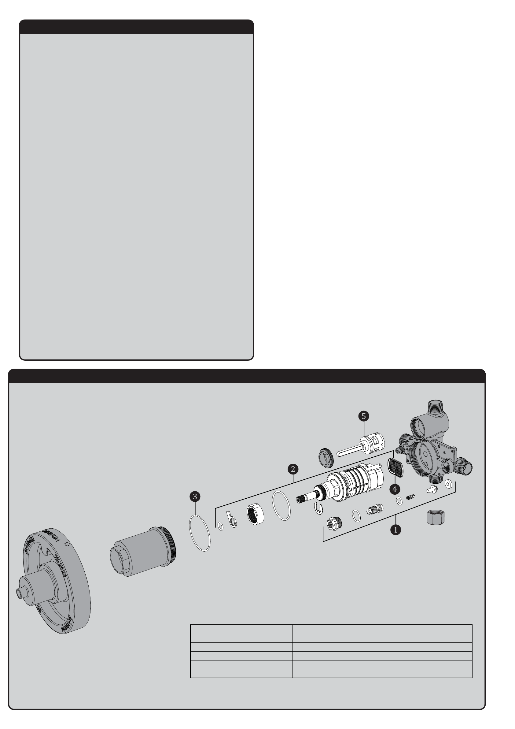
CPV-TP / CPV-TP-DV REPAIR PARTS
SPEAKMAN
®
1 RPG05-0862 CHECK STOP REPAIR KIT
2 RPG05-1109 T/P CARTRIDGE
3 RPG49-0012 BONNET O-RING
4 RPG49-0011 LOWER CARTRIDGE SEAL
5 RPG05-0897 VOLUME CONTROL/DIVERTER CERAMIC REPAIR CARTRIDGE
I
P
D
Page 5
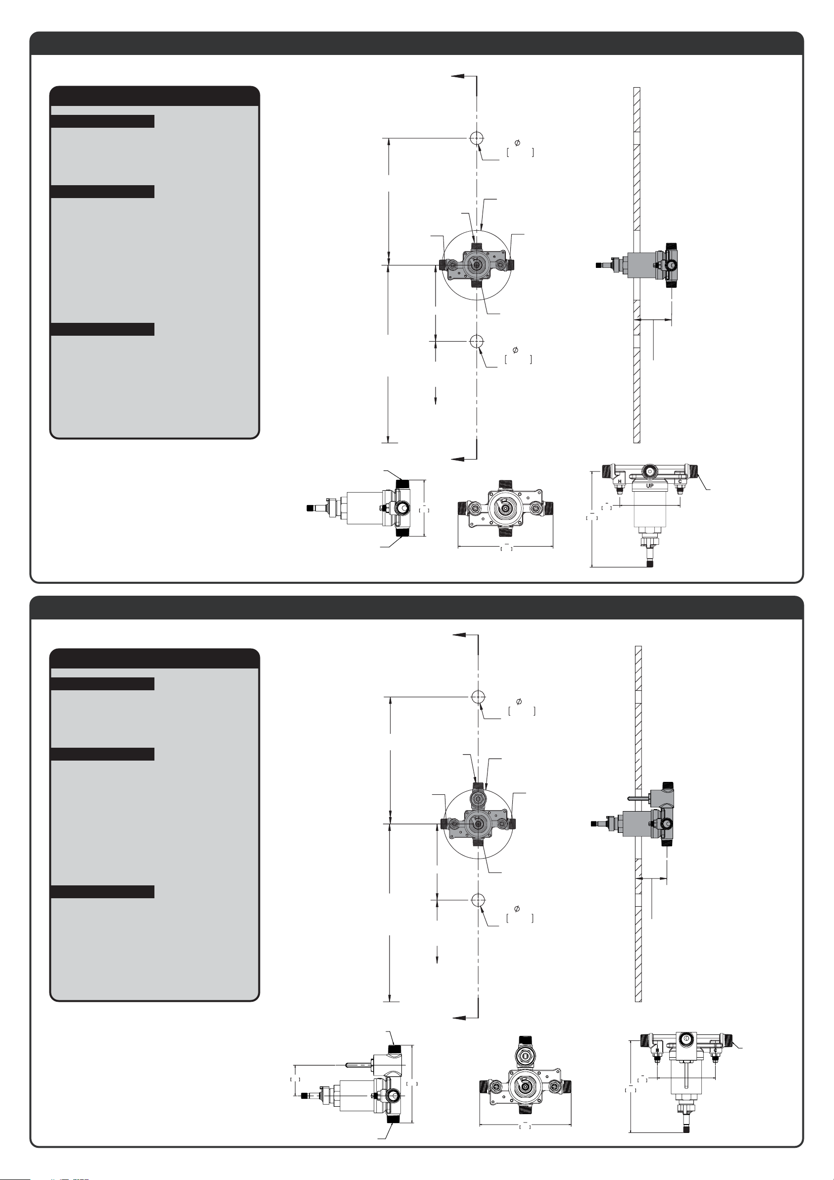
CPV-TP-DV ROUGH-IN DIAGRAM
SPEAKMAN
®
DIMENSIONS SUBJECT TO CHANGE WITHOUT NOTICE.
NOTES:
COMPLIANCE:
CONNECTIONS:
ASME A112.18.1/CSA B125.1
Shower Valve ASSE1016
Hot/Cold Inlets: ½” Female Copper Sweat
½” NPT Male
Shower Outlet: ½” Female Copper Sweat
½” NPT Male
Tub Outlet: ½” Female Copper Sweat
½” NPT Male
(Cap included for Shower Only Connections)
Contractor to supply necessary inlet
connections.
NOTES:
This valve is designed to be used in conjunction
with a shower-head rated at 1.5 gpm (5.7 L/min)
or higher flow rate
CPV-TP ROUGH-IN DIAGRAM
SPEAKMAN
®
DIMENSIONS SUBJECT TO CHANGE WITHOUT NOTICE.
6'-6" [2 METERS]
NOTES:
COMPLIANCE:
CONNECTIONS:
ASME A112.18.1/CSA B125.1
Shower Valve ASSE1016
Hot/Cold Inlets: ½” Female Copper Sweat
½” NPT Male
Shower Outlet: ½” Female Copper Sweat
½” NPT Male
Tub Outlet: ½” Female Copper Sweat
½” NPT Male
(Cap included for Shower Only Connections)
Contractor to supply necessary inlet
connections.
NOTES:
This valve is designed to be used in conjunction
with a shower-head rated at 1.5 gpm (5.7 L/min)
or higher flow rate
TO FLOOR
1/2" NPT MALE
1/2" SWEAT
CONNECTION
A
1/2" NPT MALE
1/2" SWEAT
CONNECTION
1"
25mm
HOLE FOR
SHOWER ARM
5-1/2" (140MM) DIA.
HOLE FOR
VALVE ACCESS
1/2" NPT MALE
1/2" SWEAT
CONNECTION
DIMENSIONS SUBJECT TO CHANGE WITHOUT NOTICE.
FOR ADA MOUNTING LOCATIONS, CONSULT ADAAG, ANSI
A117.1, AND STATE REGULATIONS.
4’-6" [1.4 METERS]
TO FLOOR
(SHOWER
INSTALLATION
ONLY)
SHOWER OUTLET:
1/2" NPT MALE CONNECTION
1/2 SWEAT CONNECTION
TUB OUTLET:
1/2" NPT MALE CONNECTION
1/2 SWEAT CONNECTION
1'-9" [533mm]
4" [102mm]
TO TOP OF
TUB LEDGE
A
1
"
3
2
89mm
1/2" NPT MALE
1/2" SWEAT
CONNECTION
1"
25mm
HOLE FOR
TUB SPOUT
15
"
5
16
150mm
2-1/2" MIN
[64mm]
3-1/2" MAX
[89mm]
(ADJUSTMENT)
INLETS (2):
1/2" NPT MALE CONNECTION
3
"
3
4
95mm
15
"
5
16
151mm
1/2 SWEAT CONNECTION
6'-6" [2 METERS]
TO FLOOR
1/2" NPT MALE
1/2" SWEAT
CONNECTION
4’-6" [1.4 METERS]
TO FLOOR
(SHOWER
INSTALLATION
ONLY)
A
1/2" NPT MALE
1/2" SWEAT
CONNECTION
1'-9" [533mm]
4" [102mm]
TO TOP OF
TUB LEDGE
1"
25mm
HOLE FOR
SHOWER ARM
5-1/2" (140MM) DIA.
HOLE FOR
VALVE ACCESS
1/2" NPT MALE
1/2" SWEAT
CONNECTION
1/2" NPT MALE
1/2" SWEAT
CONNECTION
1"
25mm
HOLE FOR
TUB SPOUT
2-1/2" MIN
[64mm]
3-1/2" MAX
[89mm]
(ADJUSTMENT)
DIMENSIONS SUBJECT TO CHANGE WITHOUT NOTICE.
FOR ADA MOUNTING LOCATIONS, CONSULT ADAAG, ANSI
A117.1, AND STATE REGULATIONS.
SHOWER OUTLET:
1/2" NPT MALE CONNECTION
1/2" SWEAT CONNECTION
2"
50mm
TUB OUTLET:
1/2" NPT MALE CONNECTION
1/2" SWEAT CONNECTION
128mm
5"
A
INLETS (2):
1/2" NPT MALE CONNECTION
1/2" SWEAT CONNECTION
3
"
3
15
"
5
16
150mm
4
95mm
15
"
5
16
151mm
Page 6
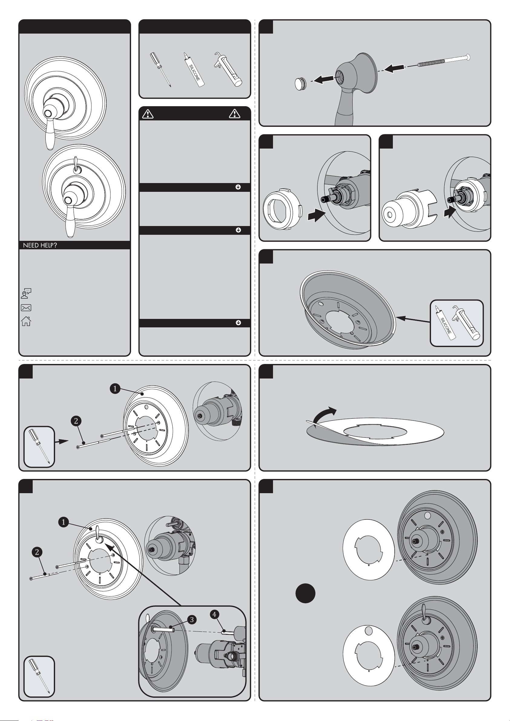
INSTRUCTIONS FOR MODELS
92-CPT-5001-01
For additional assistance or service please contact:
SPEAKMAN
®
Company
400 Anchor Mill Road
New Castle, DE 19720
800-537-2107
www.speakman.com
CPT-5001 / CPT-5401
TOOLS AND SUPPLIES
Phillips
Screwdriver
Silicone Caulk Gun
Additional warranty information can be found at:
www.speakman.com
WARRANTY
MAINTENANCE
Cover your drain to prevent loss of parts. Be sure to
wear eye protection while cutting pipe.
SAFETY TIPS
IMPORTANT
• Be sure to read instructions thoroughly before
beginning installation.
• Do not over-tighten any connections or damage
may occur.
• This valve has an operating range of 20-80 psi.
Your new Speakman Product is designed for years of
trouble-free performance. Keep it looking new by
cleaning it periodically with a soft cloth. The use of harsh
chemicals and abrasives on any of the Speakman custom
finish products may damage the finish and void the
product warranty. Please be sure to only use approved
cleaners. Please contact Speakman for any clarification
of acceptable cleaners.
1
Remove the Handle Button Screw by inserting one of the included Mounting Screws thru the hole in the Handle.
2
Insert the T/P Rubber Sleeve with Tabs over
Valve Bonnet.
3
Be sure to have properly adjusted the Temperature
Limiting Stop (TLS) as per the Valve Installation
Instructions before installing
Valve Trim. Slide Trim Sleeve
over the Rubber Sleeve.
Ensure the tabs are
properly seated within
the grooves of the
Trim Sleeve.
4
Clean wall surface. Orient Wall Plate as shown below. Apply clear silicone sealant to the backside outer flat
surface of the Wall Plate, while leaving a small area open at the bottom. This will allow for any moisture to drain.
5A
FOR CPT-5001 - Align the Wall Plate (1) as shown below. Secure to Valve with the included Mounting Screws
(2). Take care to not over tighten Mounting Screws. Remove excess sealant after securing Wall Plate to wall.
5B
FOR CPT-5401 - Align the Wall Plate (1) as shown below. Verify the Diverter Valve Stem is in the OFF (vertical)
position. Align the Diverter Drive Tube (3) on the Wall Plate to the Stem (4) of the Diverter Valve. Secure to Valve
with the included Mounting Screws (2). Take care to not over tighten Mounting Screws. Remove excess sealant
after securing Wall Plate to wall.
* VIEW FROM BACK OF WALL PLATE
6
Remove protective film from Trim Index Plate.
7
OR
CPT-5001: Slide Index Plate over
the Trim Sleeve. Align Index Plate
with the small Alignment Pin on the
Wall Plate, and hold Index Plate in
place for the next step.
CPT-5401: Slip the upper hole of
the Index Plate over the Diverter
Handle and then align the large hole
of the Index Plate over the Trim
Sleeve. Align Trim Index Plate with
the small Alignment Pin on the Wall
Plate, and hold Index Plate in place
for the next step.
Page 7
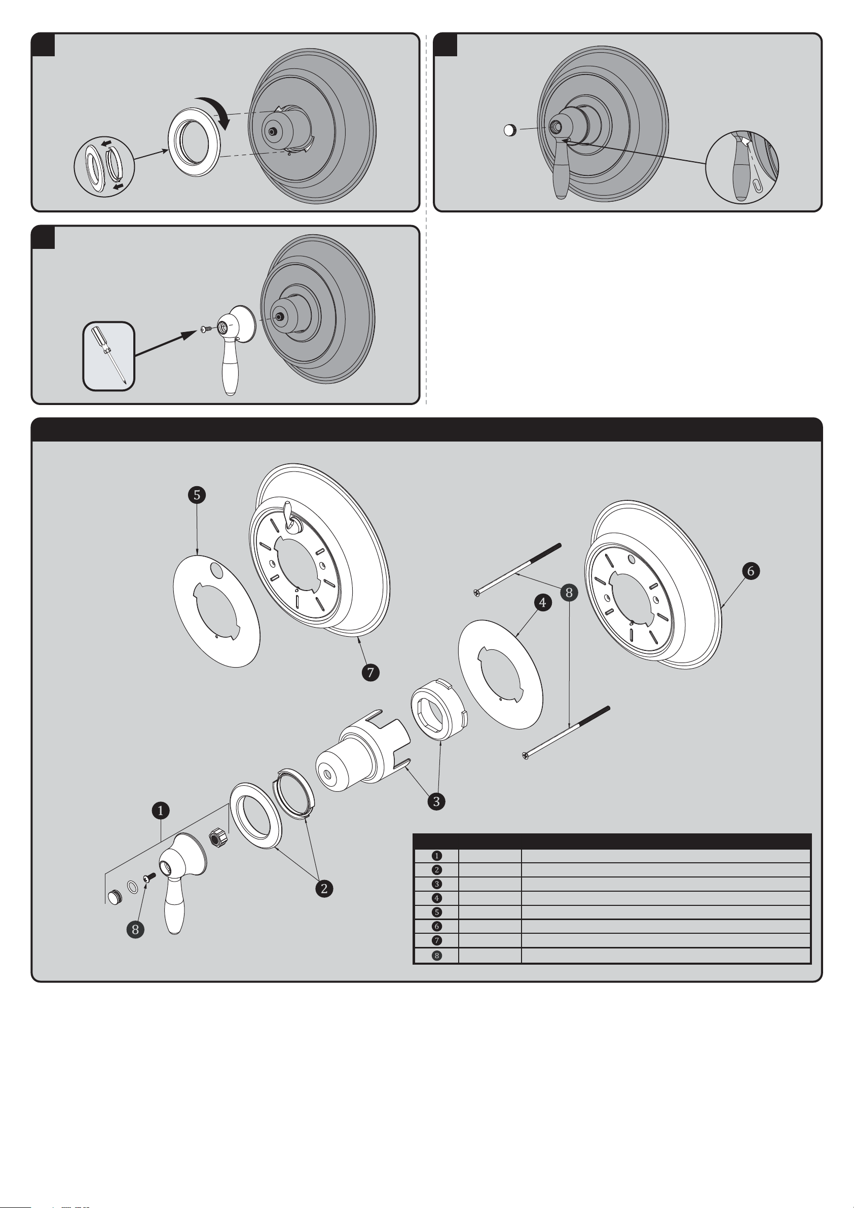
8
Ensure the Rubber Gasket is correctly installed to the Retaining
Ring. Align the Retaining Ring with the slots on the Wall Plate.
Press and Rotate the ring clock-wise until it Locks / Seals in place.
Make sure the seal is secure with the Wall Plate.
9
Temporarily place Handle over splines and adjust the valve to
the OFF position (as per the Valve Instructions). Then, align Handle
vertically as shown below. Secure Handle to Spindle with the
included #8 Screw.
10
Insert Handle Button into the Handle.
* VIEW FROM BACK UNDERSIDE OF HANDLE
If further adjustments need to be made after
the Handle Button is inserted, there is an
access hole at the back side of the handle.
Use a paper clip to push the Button back out.
CPT-5001 / CPT-5401 REPAIR PARTS
SPEAKMAN
®
ITEM NO. PART NO. DESCRIPTION
RPG04-0443 HANDLE ASSE MBLY
RPG05-1111 RETAINING RING WITH SEAL
RPG05-1110 TRIM SLEEVE AND RUBBER SLEEVE
RPG41-0286 INDEX PLATE
RPG10-0120 WAL L PL ATE
RPG10-0121 WAL L PL ATE WITH DIVERTER
RPG10-0119 MOUNTI NG HARDWARE (A LL S CREWS )
RPG41-0286-DV DIVERTER MODEL INDEX PLATE
Page 8
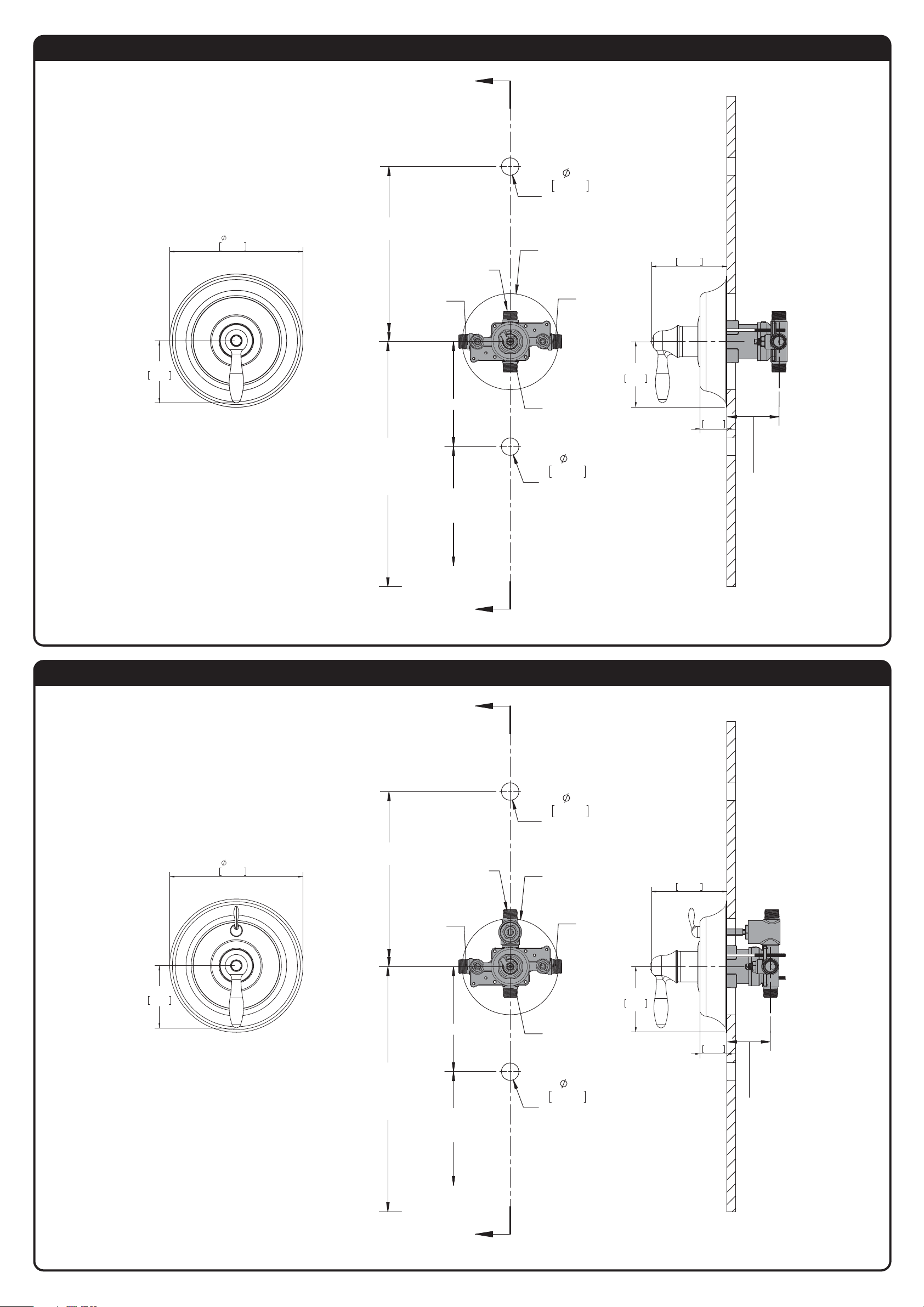
CPT-5001 ROUGH-IN DIAGRAM
SPEAKMAN
®
DIMENSIONS SUBJECT TO CHANGE WITHOUT NOTICE.
7.50in
CPT-5401 ROUGH-IN DIAGRAM
SPEAKMAN
®
DIMENSIONS SUBJECT TO CHANGE WITHOUT NOTICE.
191mm
6'-6" [2 METERS]
TO FLOOR
1/2" NPT MALE
1/2" SWEAT
CONNECTION
A
1/2" NPT MALE
1/2" SWEAT
CONNECTION
1"
25mm
HOLE FOR
SHOWER ARM
5-1/2" (140MM) DIA.
HOLE FOR
VALVE ACCESS
1/2" NPT MALE
1/2" SWEAT
CONNECTION
4.31in
110mm
3.50in
89mm
VALVE MOUNTING IS SHOWN FOR REFERENCE ONLY.
VALVE IS NOT INCLUDED WITH CPT-5000
4’-6" [1.4 METERS]
TO FLOOR
(SHOWER
INSTALLATION
ONLY)
1'-9" [533mm]
4" [102mm]
TO TOP OF
TUB LEDGE
A
1/2" NPT MALE
1/2" SWEAT
CONNECTION
1"
25mm
HOLE FOR
TUB SPOUT
3.75in
95mm
1.53in
39mm
2-1/2" MIN
[64mm]
3-1/2" MAX
[89mm]
(ADJUSTMENT)
3.50in
89mm
7.50in
191mm
6'-6" [2 METERS]
TO FLOOR
1/2" NPT MALE
1/2" SWEAT
CONNECTION
A
1/2" NPT MALE
1/2" SWEAT
CONNECTION
1"
25mm
HOLE FOR
SHOWER ARM
5-1/2" (140MM) DIA.
HOLE FOR
VALVE ACCESS
1/2" NPT MALE
1/2" SWEAT
CONNECTION
3.75in
95mm
4.31in
110mm
VALVE MOUNTING IS SHOWN FOR REFERENCE ONLY.
VALVE IS NOT INCLUDED WITH CPT-5400
4’-6" [1.4 METERS]
TO FLOOR
(SHOWER
INSTALLATION
ONLY)
1'-9" [533mm]
4" [102mm]
TO TOP OF
TUB LEDGE
A
1/2" NPT MALE
1/2" SWEAT
CONNECTION
1"
25mm
HOLE FOR
TUB SPOUT
1.53in
39mm
2-1/2" MIN
[64mm]
3-1/2" MAX
[89mm]
(ADJUSTMENT)
 Loading...