

Page 1
INSTRUCTIONS FOR MODELS
92-SB-1021-05
For additional assistance or service please contact:
SPEAKMAN
®
Company
400 Anchor Mill Road
New Castle, DE 19720
800-537-2107
www.speakman.com
SB-1021
SB-1021-E
HELPFUL TOOLS & SUPPLIES:
TOOLS AND SUPPLIES
Adjustable
Wrench
Slip Joint
Wrench
Supply
Hoses
Tubing
Cutter
Basin
Wrench
Thread Seal
Tape
Aerator
Wrench
(included)
Phillips
Screwdriver
Pipe
Wrench
Hacksaw Utility
Knife
Safety
Glasses
Additional warranty information can be found at:
www.speakman.com
WARRANTY
Your new Speakman Product is designed for years of
trouble-free performance. Keep it looking new by
cleaning it periodically with a soft cloth. The use of harsh
chemicals and abrasives on any of the Speakman custom
finish products may damage the finish and void the
product warranty. Please be sure to only use approved
cleaners. Please contact Speakman for any clarification
of acceptable cleaners.
MAINTENANCE
Cover your drain to prevent loss of parts. Be sure to
wear eye protection while cutting pipe.
SAFETY TIPS
IMPORTANT
• Be sure to read instructions thoroughly before
beginning installation.
• Do not over-tighten any connections or damage
may occur.
• This faucet has an operating range of 20-80 psi.
1
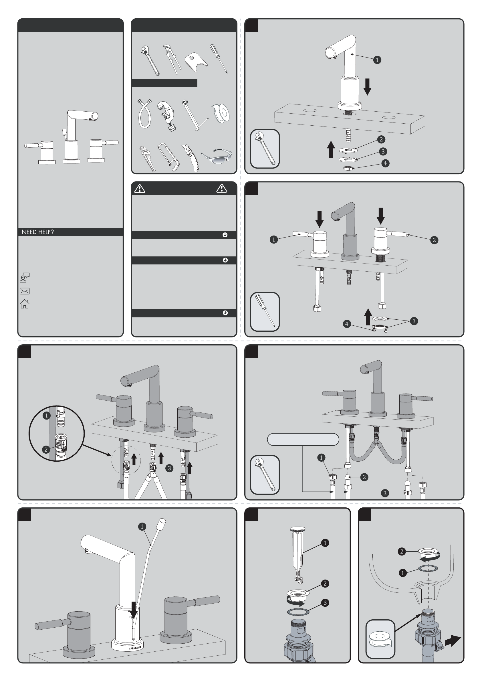
Shut off water supplies. Remove old faucet. Clean sink surface in preparation for new faucet. Place Spout ❶
thru center mounting hole. Secure Spout with Rubber Washer
❷, Metal Washer ❸ and Nut ❹.
2
Slide HOT ❶ and COLD ❷ End Valves thru mounting holes. Make sure long tubes are installed facing away
from spout. Note: Hot Side end valve is labeled. Secure end valves with Washers and Nuts
❸. Hand
tighten Nuts onto shank. Properly align handles while in the "OFF" position. Lock nuts into position by
tightening Screws
❹.
3
Align Tabs ❶ and ❷ on Quick Connects ❸. Push Quick Connect housing firmly upward and snap onto
receiving tub tab. Pull down moderately to ensure connection has been made. If it is necessary to remove quick
connect, squeeze tabs on hose between index finger and thumb, then pull down to disconnect.
4
Make connections to water lines. Use ½” IPS faucet connections (not supplied) ❶ or use the supplied
coupling nuts
❸ with 3/8” O.D. ball nose risers (not supplied) ❷. Use wrenches to tighten connections.
Do not overtighten.
INLET SUPPLIES NOT INCLUDED
5
Insert Lift Rod ❶ down into the slot in the back of the Spout. Orient Lift Rod as shown below.
6
Remove Stopper ❶, Flange Nut ❷, and Flange
Washer ❸ from Drain Assembly.
7
Apply Thread Seal Tape to threaded area of the
Drain Body. From beneath, insert Drain Assembly
through drain hole in sink. Attach supplied
Flange Washer ❶ or plumber’s putty to the
underside of the Flange ❷. Secure Flange ❷ to
the Drain Assembly. Align the Drain Assembly as
shown below.
Align
towards
faucet.
Page 2
8
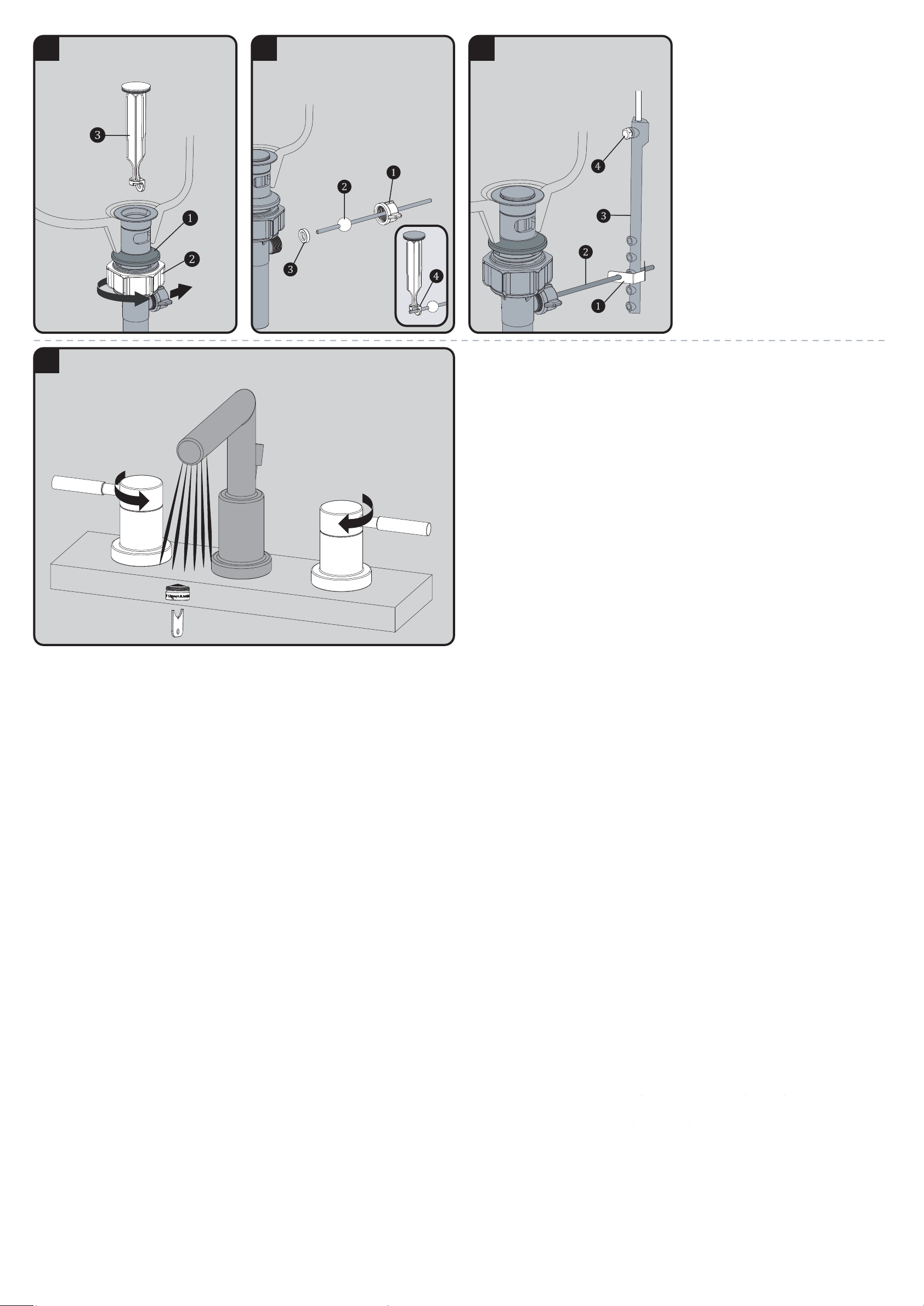
From beneath, secure Rubber Washer ❶, by
hand-tightening Nut ❷ as shown below. Place
Stopper ❸ into drain with the engagement tab at
rear as shown below.
Align
towards
faucet.
9
Remove Pivot Nut ❶, from Drain Assembly.
Install Pivot Rod ❷, and ensure that Inner Pivot
Washer ❸ is retained in Drain Assembly. Insert
Pivot Rod into Drain Assembly and install Stopper
❹ as non-removable. Secure Pivot Rod to Drain
Assembly by tightening Pivot Nut ❶.
10
Place one end of Spring Clip ❶, on Pivot Rod
❷. Insert Pivot Rod ❷ through a hole in the Lift
Rod Strap ❸. Secure with Spring Clip ❶. Insert
Lift Rod into Strap and secure with Nut ❹. Make
remaining plumbing connections to your drain
system.
11
IMPORTANT: After drain installation is completed, remove Aerator if installed, using supplied Aerator
Wrench. Turn on water supply and allow both hot and cold water to run for at least one minute each. While water
is running, check for leaks. Return the HOT and COLD handles to the "OFF" position. Replace Aerator.
Page 3
SB-1021 REPAIR PARTS
SPEAKMAN
®
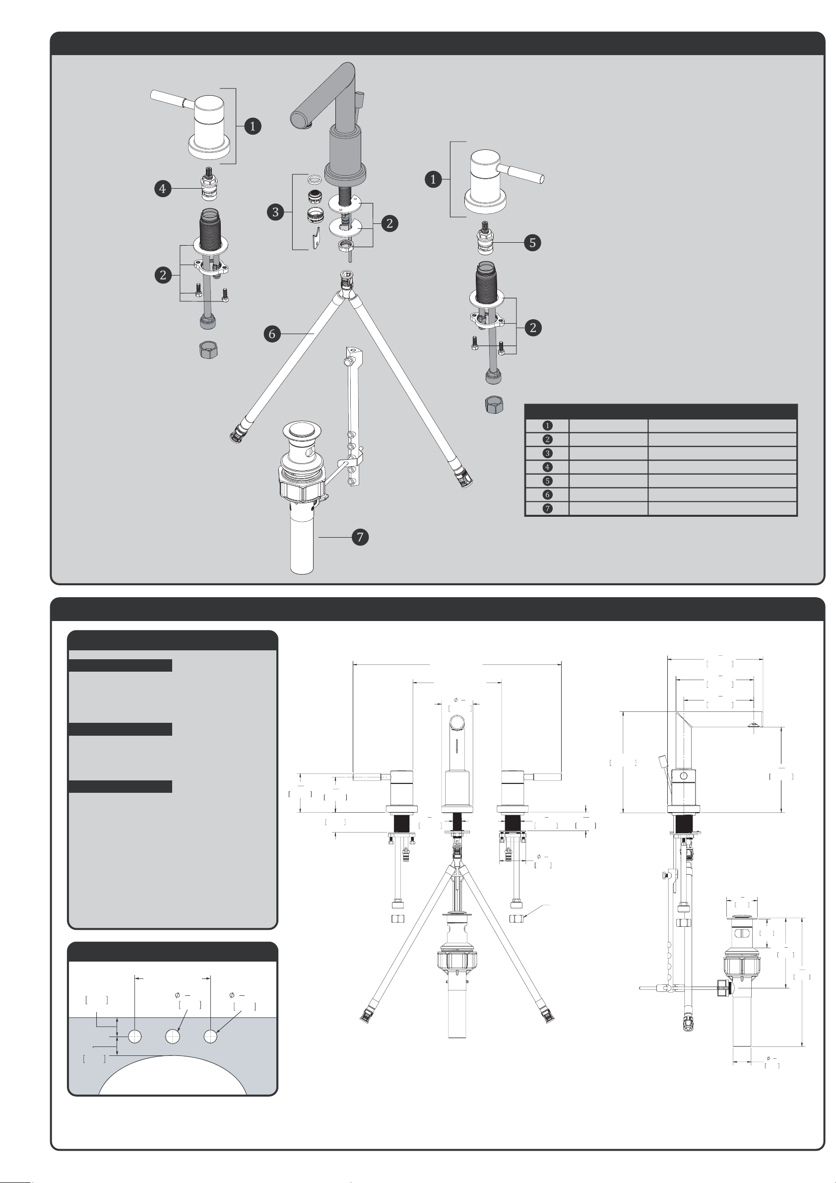
RPG04-0397-XX HANDLE ASSEMBLY (XX = FINISH)
RPG45-0046 FASTENING NUT ASSEMBLY
RPG05-40053 AERATOR ASSEMBLY 1.2 GPM
RPG05-0889 HOT VALVE
RPG05-0890 COLD VALVE
RPG63-104494 TEE/HOSE
RPG24-0127-XX POP-UP DRAIN ASSEMBLY (XX = FINISH)
ITEM NO. PART NO. DESCRIPTION
SB-1021 ROUGH-IN DIAGRAM
SPEAKMAN
®
DIMENSIONS SUBJECT TO CHANGE WITHOUT NOTICE.
NOTES:
COMPLIANCE:
FLOW:
CONNECTIONS:
ASME A112.18.1/CSA B 125.1
AB1953
NSF 372
NSF 61
Flow Rate: 1.2 gpm
Flow Type: Aerated
For flexible hose connection
Hot Supply- ½”- 14 NPSM
Cold Supply- ½” -14 NPSM
For Hard pipe/copper tube connections
Hot & cold- ½” tube connection
with coupling nut
Contractor to supply necessary connections
to the inlets of the end bodies.
2"
MIN. TO LEDGE
51mm
2"
MIN. TO WALL
51mm
LAVATORY ROUGH-IN
32mm
1
1
4
"
MIN
32mm
1
1
4
"
MIN
6” MIN - 12” MAX
2
1
4
"
57.20mm
1.44in
36.6mm
MAX DECK THICKNESS
1
7
8
"
48mm
1
5
16
"
33.9mm
2
9
16
"
64.60mm
2
13
16
"
70.95mm
6.00"~12.00"
[152.40MM~304.80MM]
13.00"~19.00"
[330.20MM~482.60MM]
5
8
"
15.56mm
1
1
8
"
28.38mm
1/2"-14 NPSM-2A
8
15
16
"
226mm
4
7
8
"
124mm
1
1
4
"
32mm
2"
51mm
MAX
2
1
8
"
54mm
7"
177.90mm
5
15
16
"
150.2mm
6
5
8
"
168.30mm
4
7
8
"
123.20mm
5
3
8
"
136.70mm
 Loading...