

Page 1
INSTRUCTIONS FOR MODELS
92-SA-3100-01
For additional assistance or service please contact:
SPEAKMAN
®
800-537-2107
www.speakman.com
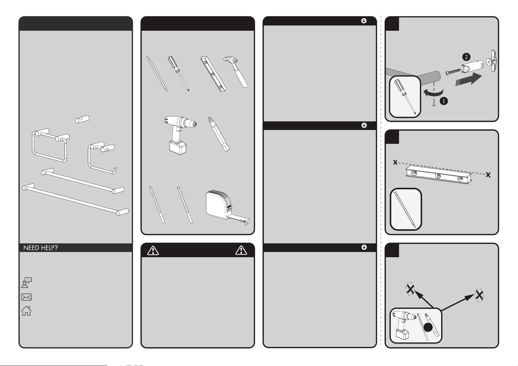
SA-3104 HAND TOWEL BAR
SA-3106 ROBE HOOK
SA-3107 TOWEL BAR
SA-3107-18 18” TOWEL BAR
SA-3110 PAPER HOLDER
TOOLS AND SUPPLIES
Phillips
Screwdriver
Pencil
Drill
Drill Bit
Ø7/16”
Drill Bit
Ø1/4”
Level Hammer
Measuring
Tape
Phillips
Drive Bit
Warranty information can be found at:
www.speakman.com
WARRANTY
MAINTENANCE
• Be sure to wear eye protection.
• If mounting to a tile surface, ensure you acquire
appropriate mounting hardware capable of supporting
the accessory in use. Follow the instructions included
with the manufacturer’s mounting hardware.
SAFETY TIPS
Your new Speakman Product is designed for years of
trouble-free performance. Keep it looking new by
cleaning it periodically with a soft cloth. The use of harsh
chemicals and abrasives on any of the Speakman custom
finish products may damage the finish and void the
product warranty. Please be sure to only use approved
cleaners. Please contact Speakman for any clarification
of acceptable cleaners.
IMPORTANT
• Be sure to read instructions thoroughly before
beginning installation.
• Do not over-tighten any connections or damage
may occur.
• This installation manual covers several models.
While the appearance of your model may vary,
the installation steps required are the same as
shown in this manual.
• This item is NOT designed for use as a grab bar.
Do not mount in locations where product is likely
to be used as a grab bar.
1
If Accessory comes pre-assembled, remove
the Set Screw(s) (1) on the bottom of the
Mounting Bracket(s) using a Philips Head
Screw Driver. Remove the Toggle Anchor(s)
and Mounting Hardware (2).
2
At the selected height, mark center point of
mounting locations onto wall referencing
the rough in diagram.
3
If mounting to dry wall, use the Plastic
Toggle Anchors (included). Drill guide holes
at marked locations using a Drill equipped
with a Ø 7/16" bit. NOTE: If mounting
to tile, acquire appropriate hardware and
follow manufacturer's installation guidelines.
Ø7/16”
OR
Page 2
4
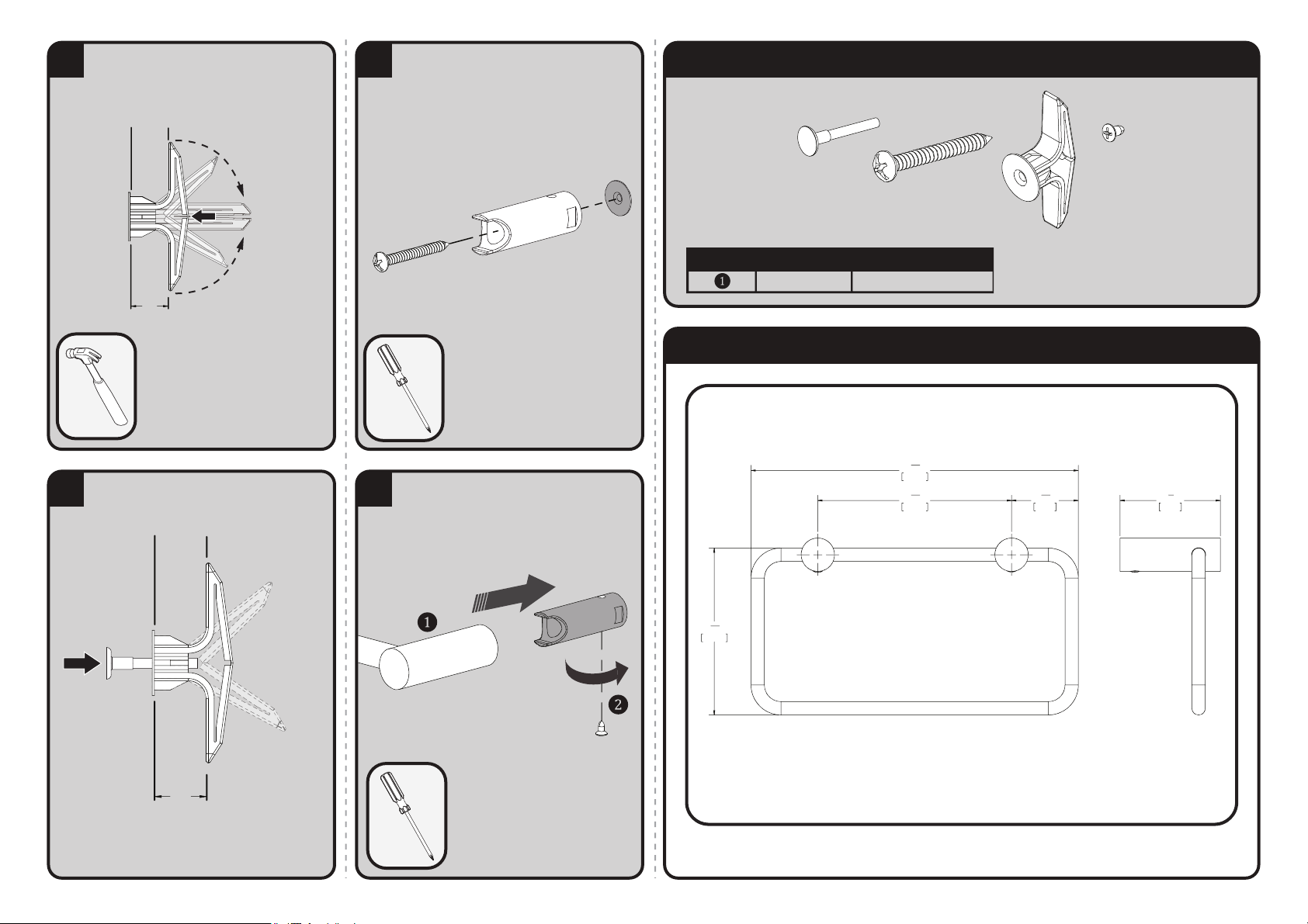
• Fold the Plastic Toggle Anchor by
pushing in the middle so that it collapses.
• Insert Plastic Toggle Anchor into drilled
holes and press/tap into place until the
head is flush to the wall surface.
WALL THICKNESS
INSERT IN CLOSED
POSITION
3/8" - 1/2"
5
Insert Pin and press in completely to pop
open the Plastic Toggle Anchor behind
the wall.
WALL THICKNESS
OPEN AND LOCK
POSITION
3/8" - 1/2"
6
Secure the Mounting Bracket(s) with the
Mounting Screw(s) provided. Verify that
the Mounting Bracket(s) are aligned
vertically as shown with the Set Screw
hole(s) positioned on the top and bottom.
7
Place Accessory (1) over Mounting Bracket.
Align the Set Screw Holes vertically as
shown. Secure the Set Screw(s) with a
Philips Head Screw Driver (2).
ROUGH-IN DIAGRAMS
SPEAKMAN
®
DIMENSIONS SUBJECT TO CHANGE WITHOUT NOTICE.
SA-31XX REPAIR PARTS
SPEAKMAN
®
RPG05-114681 MOUNTING HARDWARE
ITEM NO. PART NO. DESCRIPTION
11
7
"
16
196mm
15
3
16
100mm
9
4
"
16
116mm
"
1
16
40mm
9
"
2
60mm
3
"
8
SA-3104
Page 3
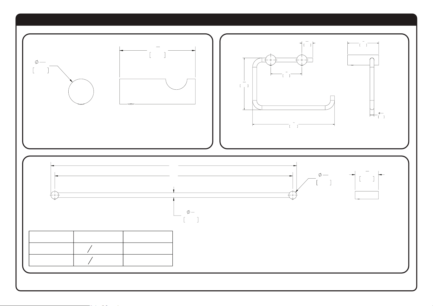
ROUGH-IN DIAGRAMS
SPEAKMAN
®
DIMENSIONS SUBJECT TO CHANGE WITHOUT NOTICE.
13
"
16
20mm
3
2
8
60mm
13
"
16
6
158mm
21mm
1
"
4
"
3
2
"
8
60mm
15
3
"
16
100mm
3
2
"
8
60mm
8mm
5
"
16
MODEL No.
SA-3107
SA-3107-18
24
18
13
16
3
" [477mm]
4
SA-3106
"A"
" [630mm]
"B"
24" [610mm]
18" [457mm]
"A"
"B"
1
"
2
13mm
SA-3107
SA-3107-18
SA-3110
13
16
20mm
3
2
"
"
8
60mm
 Loading...