

Page 1
INSTRUCTIONS FOR MODELS
92-TS-9000-02
For additional assistance or service please contact:
SPEAKMAN
®
800-537-2107
www.speakman.com
TS-9000
TOOLS AND SUPPLIES
Phillips
Screwdriver
Adjustable
Wrench
Measuring
Tape
Needle
Nose Pliers
Flat Tip
Screwdriver
Thread Seal
Tape
This product is factory equipped with a specific
electric cord and plug to permit connection to a
proper electric circuit. Make sure that the product is
connected to an outlet having the same configuration
as the plug. No adapter should be used with this
product. Do not modify the plug provided — if it will
not fit the outlet, have the proper outlet installed by a
qualified electrician. If the product must be
reconnected for use on a different type of electric
circuit, the reconnection should be made by
qualified service personnel.
DANGER: Improper use of the grounding
plug can result in a risk of electric shock
This product MUST be used with a properly
grounded electrical outlet.
GROUNDING INSTRUCTIONS
IMPORTANT
• Close supervision is necessary when this product is
used by, on, or near children or individuals with
disabilities.
• Use this product only for its intended use as
described in this manual. Do not use attachments not
recommended by the manufacturer.
• Never operate this product if it has a damaged
cord or plug, if it is not working properly, if it has
been dropped or damaged, or dropped into water.
• Keep the cord away from heated surfaces.
• This appliance MUST be plugged directly into a
properly grounded electrical outlet. Extension cords
are NOT permitted. (See Grounding Instructions.)
• Do not throw cigarettes and/or other ignited
materials into toilet.
• This product is an electric appliance, avoid direct
contact with water or other liquids.
• Do not position the product on its side or upside
down while making electrical connections.
• It is not recommended to use other electric
appliances in the same outlet.
• Do NOT reuse any existing water supply hoses,
otherwise it might cause leakage, fire or electrical
shock. Installation of the bidet seat should include
specified components and new water supply hose.
WARNING: To reduce the risk of burns,
electrocution, fire, or injury to persons:
1 Year Limited Warranty
Warranty information can be found at:
www.speakman.com
WARRANTY
IMPORTANT
• Do not install or use the product in wet or damp
locations such as a steam room.
• Ensure the electrical outlet is positioned where it
will not come in contact with water.
• This product is to be used with an electrical system
rated at 110V-120V, 50/60Hz. The circuit must be
capable of supporting a minimum of 15A.
• It is recommended to unplug the unit during
thunderstorms to prevent electrical damage.
• Do not stand on product, seat or seat cover.
• Do not lean against the seat cover when using the
product.
• This product is equipped with a soft-closing seat
cover. Do not push the toilet seat closed, or damage
may occur.
• Do not use any caustic chemicals to clean this
product.
• Exposure to direct sunlight is not recommended.
• Do not connect water supply to a HOT water
supply. Make sure inlet water temperature is
between 37.4~95ºF.
• Do NOT expose the Bidet Seat or Toilet to freezing
conditions.
• If the unit will not be used for an extended period
of time, it is recommended to unplug the electrical
connection, turn of water supplies, and drain any
water present in the Bidet.
• If the unit is malfunctioning, unplug from electrical
connections, and turn OFF water supply.
CAUTION: Failure to follow the
instructions may cause bodily injury
or property damage.
1. Do not place or store product where it can fall or
be pulled into a tub or sink.
2. Do not place in or drop into water or other liquid.
3. Do not reach for a product that has fallen into
water. Unplug immediately.
4. Do not wash the main unit or electrical plug with
water or detergent.
5. Do not handle the electrical plug with wet hands.
6. Never block the outlet of the air dryer.
7. Never disassemble, repair or modify this product.
8. Ensure Power Cable is unplugged during the
installation and maintenance of the appliance.
DANGER: To reduce the risk of
electrocution:
SAFETY TIPS
IMPORTANT
When using electrical products, especially when
children are present, basic safety precautions
should always be followed, including the following:
• This product is not intended for children (without
proper adult supervision).
• This product is not intended for individuals with
reduced physical, sensory, or mental capabilities.
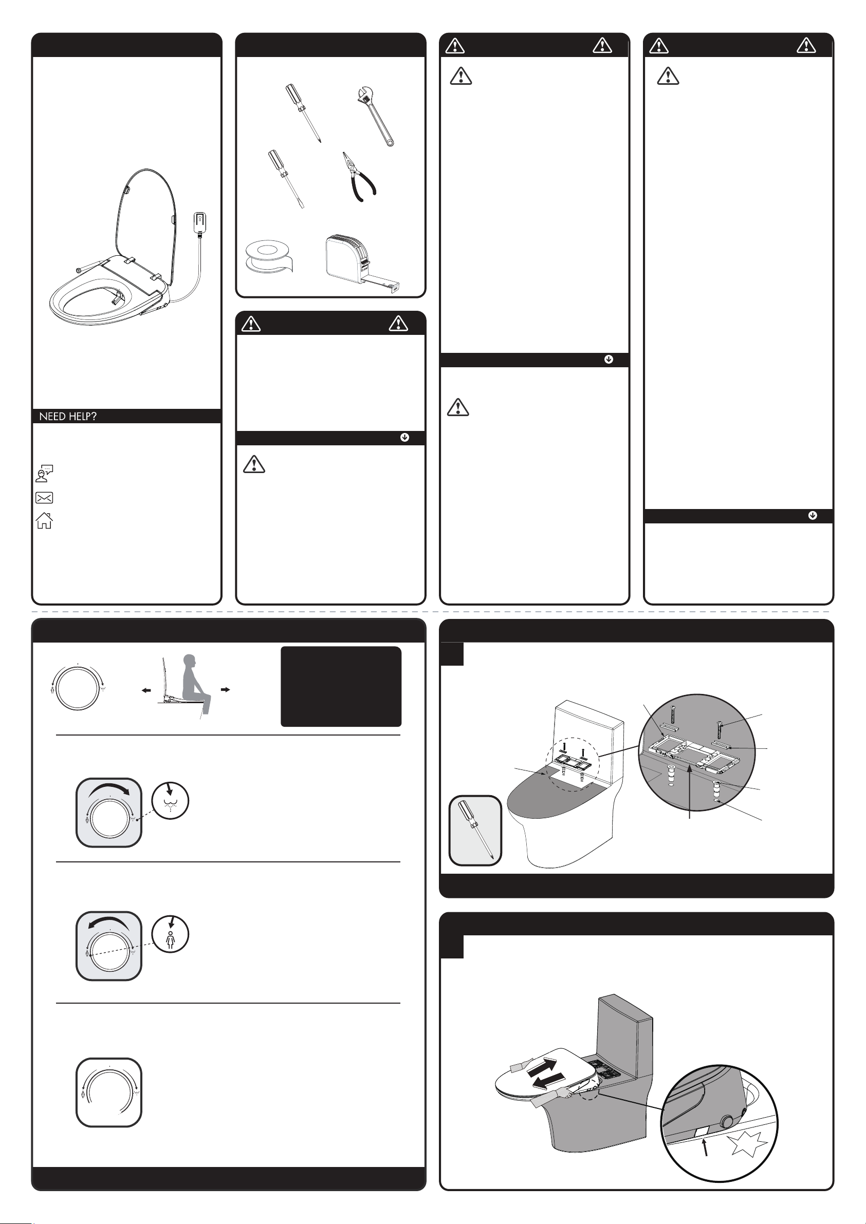
MAIN UNIT KNOB INSTRUCTIONS (KNOB ACTIVATION)
NOTE: The Cleaning Cycle will stop automatically when complete, or can be stopped at any time by pressing
the STOP button. The Drying Function will need to be manually activated if the Cleaning Function was stopped mid-cycle.
1. While seated, turn Cleaning Knob forward to
start rear cleaning function.
• Rear cleaning (about 2 minutes)
• Drying (about 2.5 minutes)
• Drying cycle will stop automatically when
completed.
2. During the rear cleaning process, turning the
knob forward will move the washing position further
forward.
REAR
CLEANING
KNOB
1. While seated, turn Cleaning Knob rearwards
to start front cleaning function.
• Front cleaning (about 2 minutes)
• Drying (about 2.5 minutes)
• Drying cycle will stop automatically when
completed.
2. During the front cleaning process, turning the
knob rearwards will move the washing position
further rearward.
FRONT
CLEANING
KNOB
Press the Activation Knob to Stop the function in
progress: Rear Cleaning, Front Cleaning, Drying or
Nozzle Cleaning Function.
STOP
KNOB
FRONT BACK
NOTE: The timing shown is the
Maximum Cycle Time
before the unit will switch
to the next function or turn OFF if it is
on the last function in that process.
User can press the Stop Button
or Press the Knob to stop
the cleaning function early.
1
INSTALL
MOUNTING
CARDBOARD
❸ SCREWS
❹ WASHER
❶ EXPANSION NUT
TOILET MOUNTING
HOLES
❷
BASE PLATE
THE BLACK LATCH
FACES FORWARD,
GROOVE UP
NOTE: This product has been tested for water flow before leaving the factory.
There may be a small amount of residual water still in the unit that spills out during installation.
IMPORTANT! Do NOT install unit where it may come in direct contact with water.
• Install the Expansion Nuts (1) into the Toilet Mounting Holes first, and then install Base Plate (2), Washer (3)
and Screws (4) in sequence according to the below illustration, then tighten.
2
REMOVAL BUTTON
CLICK
• Main Unit Installation: Align Main Unit to Base Plate and slide it into the Base Plate. The components will
audibly "click" together when properly installed.
• Removal of Main Unit: Press the "Removal button", and pull out the Main Unit when a "click" sound is
heard.
NOTE: Once the Removal Button is pressed, you do not have to hold it in during the removal process.
BASE INSTALLATION
MAIN UNIT INSTALLATION
Page 2
4
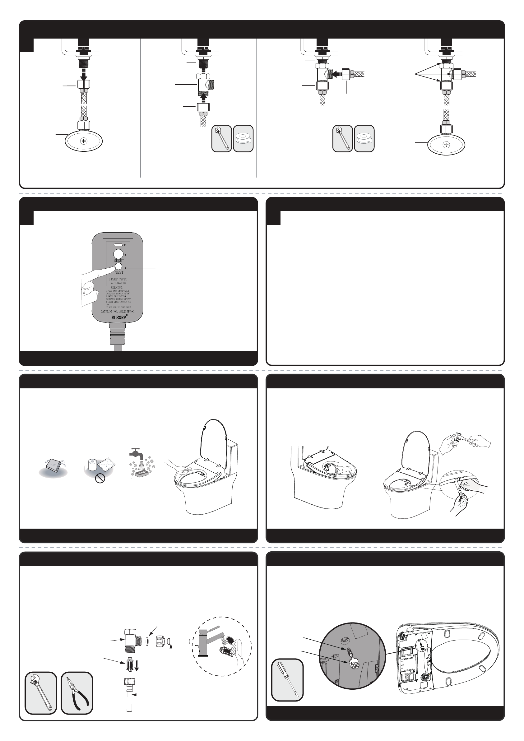
CURRENT DETECTION
TEST BUTTON
RESET BUTTON
INDICATOR LIGHT
NOTE: Press the TEST button (then RESET button) every month to ensure proper operation.
• Insert the Power Adapter into the electrical outlet.
• Press the Reset Switch. The Indicator Light on the power adapter will illuminate to show that the power is ON.
POWER CONNECTION SET-UP
5
When the unit powers on for the first time, it will perform an Automatic Testing Routine. This routine is as
follows:
• The Main Unit will beep once, then the purple light on the Function Knob will flash on and off, and the testing
routine will begin. The light will continue to flash throughout the test. Do not use the seat during this time.
• At the conclusion of the test, the flashing purple light on the function knob will turn solid, signaling that the test
is complete.
• The Bidet Seat is now ready for use.
ROUTINE CLEANING
1. Unplug from electrical outlet while cleaning.
2. Use only a soft, damp cloth to clean. Avoid using harsh chemicals.
3. Once cleaning is completed and all surfaces are dry, plug the Power Adapter back into the electrical outlet.
NOTE: Do not rinse the surface of the product directly with water during maintenance.
NEUTRAL CLEANER
NOZZLE MAINTENANCE
NOTE: Do not pull the Nozzle Housing to prevent damage of the Nozzle and motor.
1. To clean the nozzle, perform a Short Press to the Rear Cleaning Button while not sitting on the unit. The nozzle
will extend outward to allow access for cleaning.
2. The Spray Nozzle can be removed and cleaned separately. While holding the Nozzle Housing with one
hand, remove the Nozzle itself by gently pulling it towards you with the other hand.
3. Once cleaning is completed, reinstall the Nozzle to the Nozzle Housing. Press the "Stop" button on the main
unit to return the Nozzle Rod to its normal position.
SELF-CLEANING WATERWAY MAINTENANCE
NOTE: Ensure the power supply is unplugged when working on unit.
When the Self-Cleaning Waterway is blocked, or if there is no water coming out during Self-Cleaning process:
1. Turn OFF the water supply at the Stop Valve.
2. Unplug the Power Supply Cord from the electrical outlet.
3. Remove the Seat by following STEP 2, press the Flow Reset Valve in the middle with a flat tip screwdriver,
then reinstall the Seat, and turn ON the water supply at the Stop Valve.
4. If there is still no water coming out after pressing the Flow Reset Valve, use a flat tip screwdriver to unscrew
the Reset Valve Cover, then remove the Flow Reset Valve. Clean it with a small brush. Once cleaned, re-seat the
components into the shaft shown below.
5. Reinstall the Seat by following STEP 2, then turn ON the water supply.
FLOW RESET
VALVE
RESET VALVE
COVER
FILTER MAINTENANCE
FILTER
(REMOVE WITH A NEEDLE NOSE PLIER)
FILTER WASHER
TOILET SUPPLY LINE
BIDET SUPPLY LINE
SUPPLY TEE
If poor spray performance occurs under normal conditions:
1. Turn OFF the water supply at the Stop Valve.
2. Using an Adjustable Wrench, unscrew both the Supply Line to the Toilet and to the Bidet Seat from the
Supply Tee.
3.
Remove Filter and Filter Washer using Needle Nose Pliers. Clean out Filters under running water using a small brush.
4. Reinstall Filters and Water Supply Lines to Supply Tee.
Note: Ensure that the Filter is reinstalled in the orientation shown.
5. Wrench tighten connections. Take care to not over-tighten or damage may occur.
• Turn OFF water supplies at the Stop Valve.
• Unthread existing Toilet Supply Line from Toilet Fill
Valve. The Toilet Fill Valve inlet is located at the base
of the Toilet Tank.
• Install the included Tee on to the Toilet Fill Valve.
Do NOT over-tighten or damage may occur.
• Re-install Toilet Supply Line to bottom port of Tee.
TOILET FILL VALVE
EXISTING TOILET
SUPPLY LINE
INCLUDED
SUPPLY TEE
TOILET FILL VALVE
EXISTING TOILET
SUPPLY LINE
INCLUDED
SUPPLY TEE
BIDET WATER
INLET LINE
• Install the Bidet Water Inlet Line to the Side Port of the
Supply Tee.
TOILET FILL VALVE
EXISTING TOILET
SUPPLY LINE
TURN “OFF”
STOP VALVE
TURN “ON”
STOP VALVE
CHECK FOR
LEAKS
• Tighten connections. Take care to not over-tighten
connections or damage may occur.
• Turn “ON” water supply at the Stop Valve and inspect
for leaks.
PLUMBING CONNECTIONS
3
INITIAL START UP TEST
Page 3
DEODORIZING DEVICE MAINTENANCE
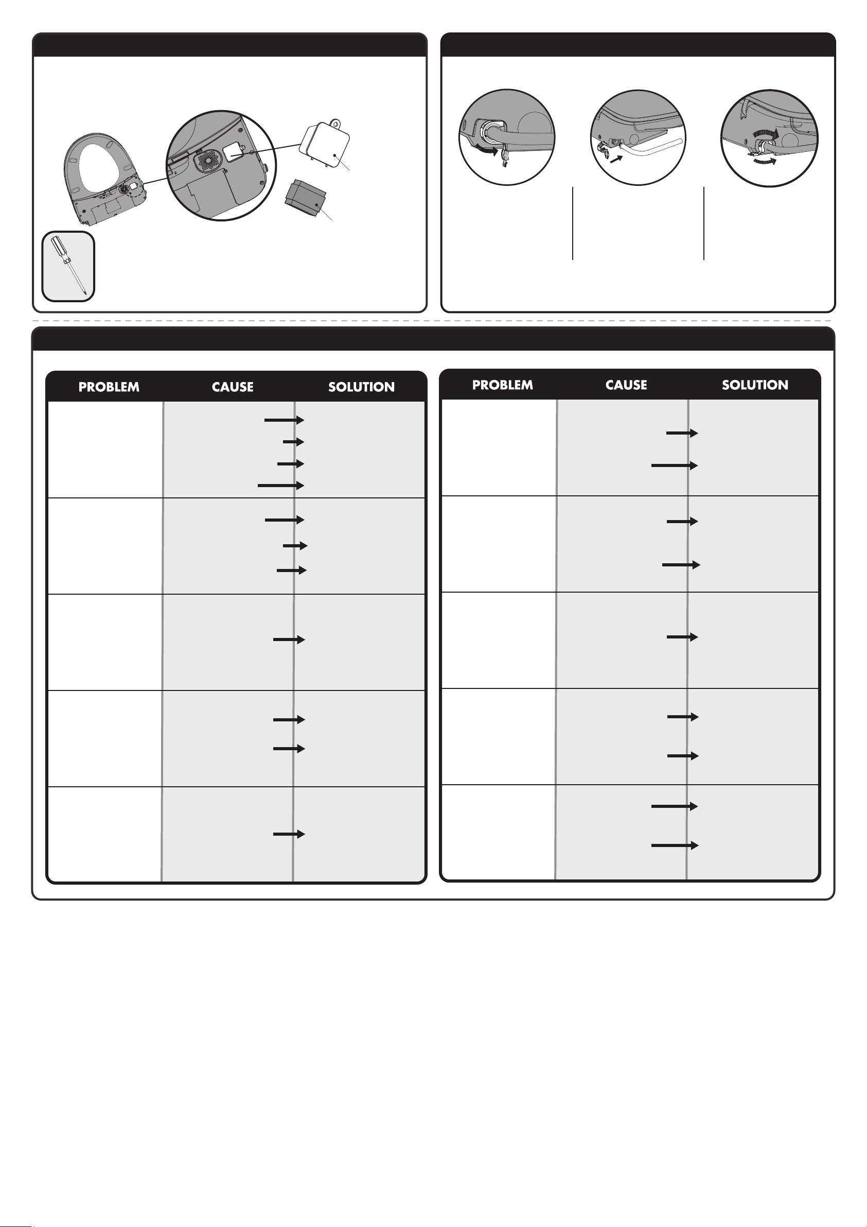
• Remove the seat assembly as outlined in STEP 2.
• Remove the screw from the underside of unit as shown below to access the Deodorizing Cartridge.
• Replacement of the Deodorizing Cartridge is recommended every 3 years.
Note: It is normal for the Deodorizing Function to continue its operation after the user leaves the seat.
This is to ensure complete removal of odors.
CARTRIDGE
HOUSING
DEODORIZING CARTRIDGE
REMOVAL AND INSTALLATION OF PRE-INSTALLED HOSE CLAMP
Removal: Open the Clamp
Cover, rotate it counterclockwise,
and use a Flat Tip Screwdriver to
pry the Clamp out of the slot.
1. Rotate the Clamp until the
opening faces down.
2. Close the Clamp cover.
❶
❷
Installation: Push the Inlet
Tubing into the Quick-Connect
Fitting on the unit. Secure with
provided Hose Clamp.
TS-9000 TROUBLESHOOTING
Ensure inlet hose is directly
connected to the unit and is not
kinked or bent
Water Inlet hose is bent or
kinked
Turn the Inlet Stop Valve "ON"
Inlet Stop Valve is turned "OFF"
Connect water supply and wait
for the water
Water supply is not connected
Ensure user is making full skin
contact to entire bidet seat
Unit does not sense user
No Water is Released
from the Spray Nozzle
Poor Water Pressure
Turn the Inlet Stop Valve "ON"
Inlet Stop Valve is not fully open
Remove and clean Filter as
outlined in the “Filter
Maintenance” Section
Inlet filter is blocked/clogged
Ensure inlet hose is directly
connected to the unit and is not
kinked or bent
Water Inlet hose is bent or
kinked
High or Low Water
Temperature
Adjust the water temperature on
the Remote Control
The water temperature is set
too high or too low
High or Low Seat
Temperature
Adjust the seat temperature on
the Remote Control
The seat temperature is set
too high or too low
Switch to Operating Mode and
allow up to 3 minutes for the
seat to warm up.
The unit is in Standby or
Power Saving Mode
High or Low Seat
Temperature
Adjust the dryer temperature on
the Remote Control
The dryer temperature is set
too high or too low
Nozzle Rod does not
retract
Clean out the Nozzle as
outlined in the “Nozzle
Maintenance” section
The Nozzle Rod is clogged
Ensure power supply is
connected. If connected, reset
the GFCI power adapter.
There is no power to the unit
Remote Control is not
working
Reinstall the batteries in the
correct orientation
The batteries in the Remote
have been installed in the
wrong orientation
Replace the batteries
The batteries in the Remote
are old and cannot supply
enough power
Malfunction of the
Deodorization Cartridge
It is normal for the
Deodorization Function to
continue after the user leaves.
This ensures complete removal
of odors
Deodorization function
continues after the user
leaves.
Ensure user is making full skin
contact to entire bidet seat
Unit does not sense user
Dryer is not blowing
Ensure user is making full skin
contact to entire bidet seat
Unit does not sense user
Switch to Operating Mode to
use dryer function.
The unit is in Standby or
Power Saving Mode
Nozzle Rod does not
extend
Ensure power supply is
connected. If connected, reset
the GFCI power adapter.
There is no power to the unit
Page 4
TS-9000 REPAIR PARTS
SPEAKMAN
®
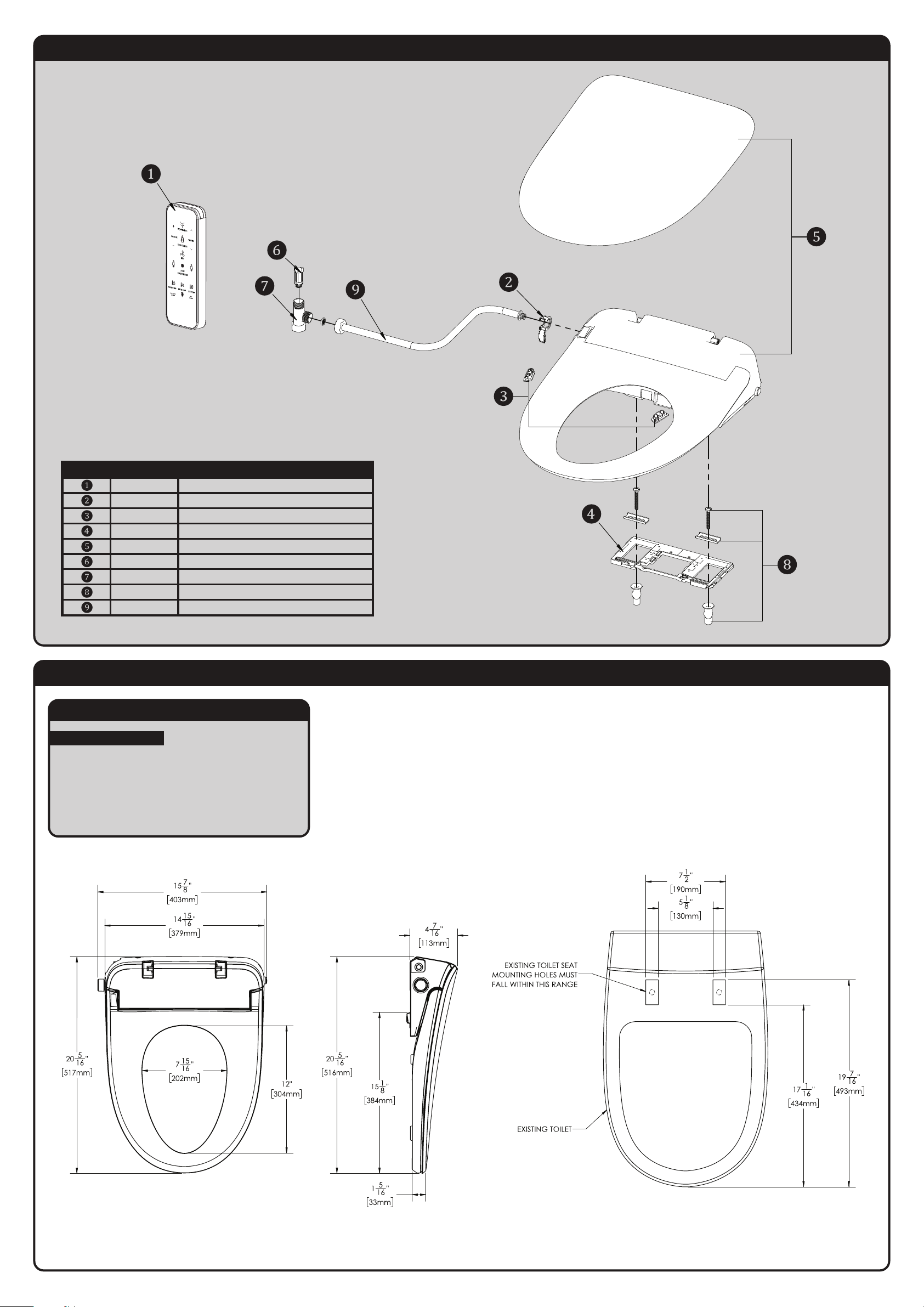
RPG05-116376 BIDET REMOTE CONTROL
RPG05-116385 HOSE CLAMP
RPG05-116386 SEAT DAMPENER
RPG05-116387 MOUNTING PLATE
RPG05-116388 TOILET SEAT COVER
RPG21-116390 INLET FILTER
RPG24-116375 SUPPLY TEE
RPG48-116384 MOUNTING HARDWARE
RPG63-116383 INLET HOSE
ITEM NO. PART NO. DESCRIPTION
L
I
G
HT
TS-9000 ROUGH-IN DIAGRAM
SPEAKMAN
®
DIMENSIONS SUBJECT TO CHANGE WITHOUT NOTICE.
* ONLY FITS ON AN ELONGATED TOILET.
NOTES:
COMPLIANCE:
ASME A112.4.2/CSA B45.16
UL 1431
CSA C22.2 No. 68
CSA C22.2 No. 64
Contractor to supply necessary inlet connections.
 Loading...