

Page 1
INSTRUCTIONS FOR MODELS
92-SF-9100-02
For additional assistance or service please contact:
SPEAKMAN
®
800-537-2107
www.speakman.com
SF-9100
SF-9200
HELPFUL TOOLS & SUPPLIES:
TOOLS AND SUPPLIES
Adjustable
Wrench
Phillips
Screwdriver
Pencil
Aerator
Wrench
(included)
Mounting
Hardware
(not included)
Drill
3/8"
Wrench
Safety
Glasses
Warranty information can be found at:
www.speakman.com
WARRANTY
MAINTENANCE
Cover your drain to prevent loss of parts. Be sure to
wear eye protection while cutting pipe.
SAFETY TIPS
IMPORTANT
• Be sure to read instructions thoroughly before
beginning installation.
• Do not over-tighten any connections or damage
may occur.
• This faucet has an operating range of 20-80 psi.
Your new Speakman Product is designed for years of
trouble-free performance. Keep it looking new by
cleaning it periodically with a soft cloth. The use of harsh
chemicals and abrasives may damage the finish and
void the product warranty. Please be sure to only use
approved cleaners. Please contact Speakman for any
clarification of acceptable cleaners.
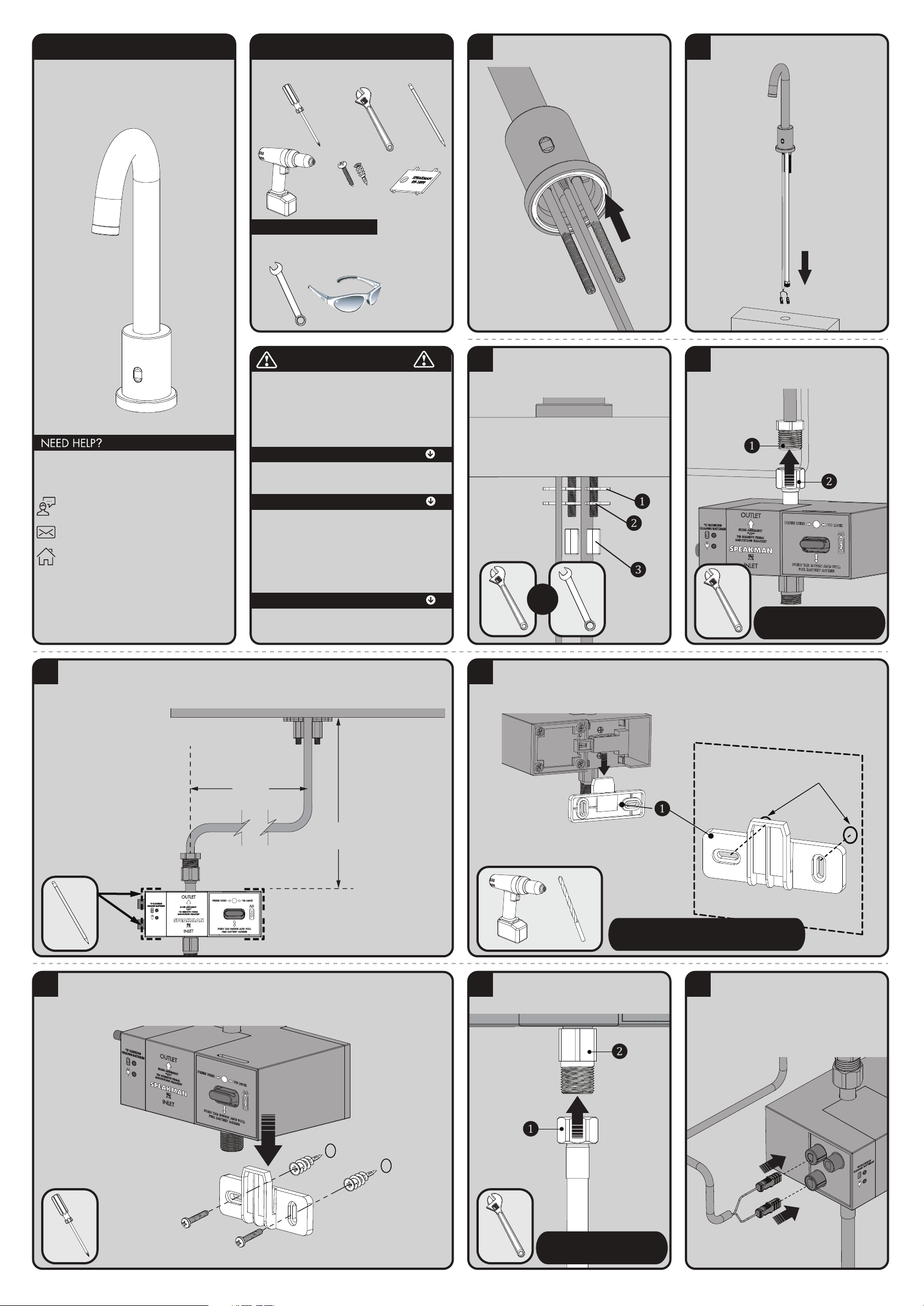
1
Verify that the Rubber Gasket is in position and
aligned to the base of the Faucet.
2
Place Hose and Sensor Wire carefully, one at a
time, thru hole in mounting surface. Lower Faucet
into position.
3
From below, install Rubber Washer (1), Metal
Washer (2), and secure with Mounting Nuts (3).
Align Faucet to desired position and wrench
tighten Mounting Nuts (3).
OR
4
Assemble the Solenoid "OUTLET" Hose of the
Faucet (1) to the "OUTLET" connection (2) of
Solenoid. Wrench tighten.
DRY CONNECTION ONLY.
DO NOT USE ANY SEALANT
ON THIS CONNECTION
5
Place the Solenoid Assembly against the desired mounting surface while ensuring adequate clearance for
servicing of all connections. If using the optional A/C Adapter, consider the distance to the nearest electrical
outlet. Solenoid Assembly should be mounted so the inlet and outlet ports are aligned vertically. Mark location
of Solenoid Assembly on the mounting surface using a pencil.
10-7/8”
(275mm)
MAX
LEFT OR RIGHT
OF CENTER
9-7/16”
(240mm)
MAX
6
Remove Mounting Bracket (1) from Solenoid Assembly. Using the previously marked location on mounting
surface, align Mounting Bracket (1) horizontally to approximate position and mark the mounting locations with a
pencil. If mounting on drywall and not to stud, use the appropriate anchors and fasteners for application.
Recommend screw in easy anchor or equal for drywall.
IMPORTANT NOTE
Verify that all hoses are free from bends or kinks.
7
After securing the Bracket to the mounting surface, align and slide Solenoid Assembly over Mounting Bracket.
8
Assemble "INLET" Supply Hose (1) (not supplied),
to the "INLET" connection (2) of Solenoid.
Wrench tighten.
DRY CONNECTION ONLY.
DO NOT USE ANY SEALANT
ON THIS CONNECTION
9
Make electrical connections from the Sensor
Eye to the Solenoid Assembly. Connect the Blue
Male Ended Wire to the Blue Female Connection.
Connect the Green Male Ended Wire to the
Green Female Connection. To further aid proper
alignment, there are white alignment lines on the
connector ends. These alignment lines should
face forward when properly installed.
GREEN
BLUE
Page 2
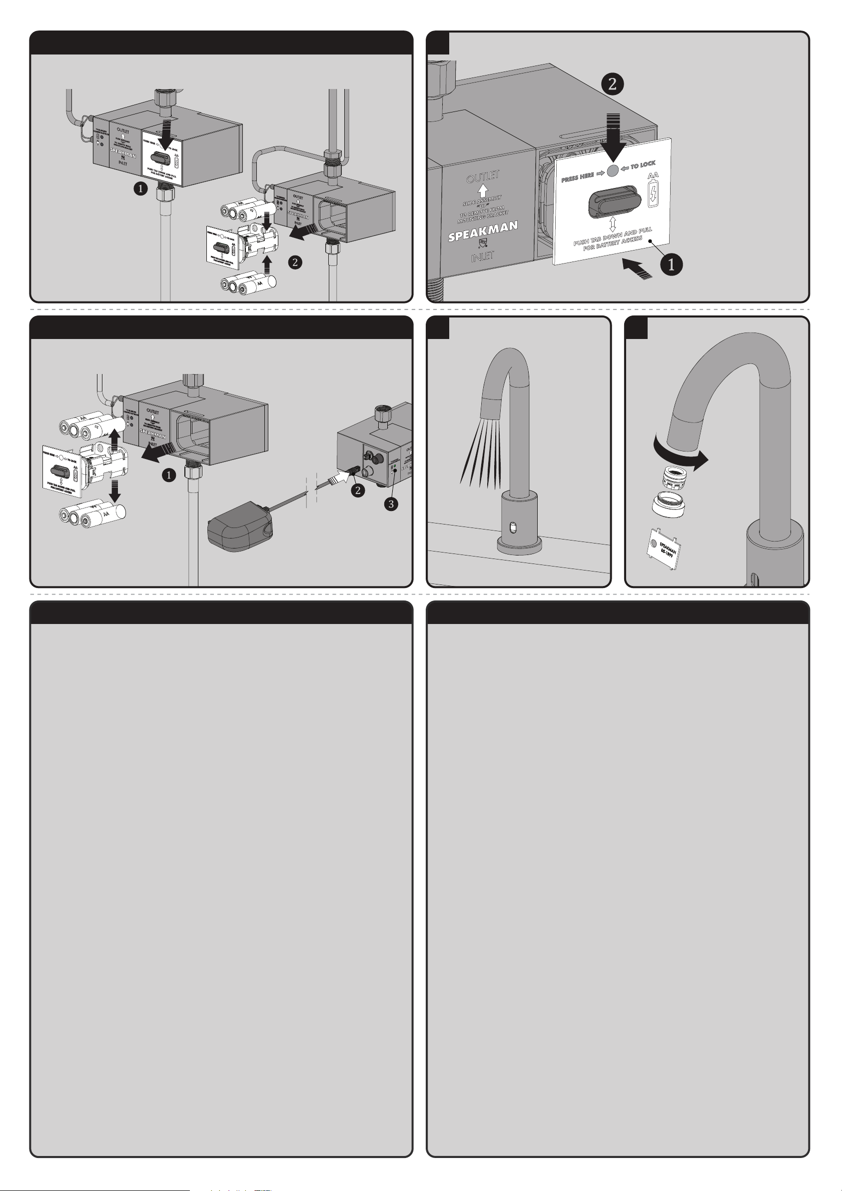
10 FOR BATTERY MODEL (SF-9100)
Access the interior Battery Enclosure by pressing down on the tab to release the tray holding the batteries (1).
Pull out Battery Tray (2). Insert or replace the batteries with six (6) new standard 1.5v AA batteries. Ensure the
position of the new batteries are aligned to the plus (+) and minus (-) symbols within the battery holder.
11
Reinstall the Battery Tray (1). Make sure to press the indicated location until the battery door is fully seated and
locks into position (2).
12 FOR A/C MODEL (SF-9200)
Verify that no batteries are present within the battery enclosure (1). Connect the A/C Adapter to the Solenoid
Body (2). Plug the A/C Adapter into the wall outlet. The A/C light (3) should illuminate.
13
Turn on water supplies. Activate faucet by
waving your hand across the Sensor Eye to flush
the water for 1 minute.
14
Install Aerator. Tighten with included Aerator
Wrench.
SF-9100 / SF-9200 TROUBLESHOOTING
If water flow from the Faucet decreases:
1) Make sure the supply stops are open.
2) Remove the Aerator from the spout using the outlet wrench. Operate the Faucet with
outlet device removed. If water flow is acceptable, disassemble the outlet device and rinse
components with clean water.
If no water flows from the Faucet, and
If you can hear a clicking sound of Solenoid opening, but no water flows:
1) Verify that the HOT and COLD wall stops are completely open.
2) If the Battery Light within the Sensor Eye or Solenoid blinks continuously, even when
the Faucet is not in use, the batteries within the Solenoid have low voltage and need
replacement.
If you do not hear a clicking sound of Solenoid opening and no water flows:
1) If the Battery Light within the Sensor Eye blinks continuously, even when the Faucet is
not in use, the batteries within the Solenoid have low voltage and need replacement.
2) Unplug connections to Solenoid for 2 minutes. Plug connections back in. The red light
on the Sensor should turn on for several seconds before becoming operational. If not,
check power supplies and connections.
3) Disconnect the existing Solenoid Assembly and connect a new Solenoid Assembly.
Activate the Sensor and check for water flow. If the water flows, the existing Solenoid
Assembly should be replaced.
If the batteries have been replaced, but the Faucet still does not operate:
1) Check the battery polarity and electrical connections. Make sure all electrical
connections are fully inserted.
2) If the Faucet does not operate, replace the existing Solenoid Assembly with one you
know to be functioning.
If the Faucet activates, but the water will not shut off:
1) Hold a hand in front of the Sensor at up to 7" away for more than 1 minute until the
water flow stops. Once the water stops, remove your hand and wait 15 seconds. Then
place your hand in front of the Sensor and verify that it is operating properly.
2) If the Faucet still does not shut off, cover the front of the sink with a towel. This will
eliminate the potential of reflections activating the Sensor.
3) If it is a new installation and still not working, replace the Solenoid Assembly.
SF-9100 / SF-9200 QUESTIONS & ANSWERS
Q. How does the Sensorflo® Faucet work?
A. It uses laser technology. The Sensor emits a non-visible beam of light. When an object
enters the detection area, the Sensor signals the Solenoid Valve to open for water to flow.
When an object leaves the detection area, the Sensor signals the valve to close.
Q. Is the Sensorflo
®
Faucet sensor beam adjustable?
A. No, the Sensorflo
®
Faucet sensor beam is not adjustable. It has been factory set to
factory specifications for these Faucets.
Q. What about water conservation?
A. The Sensorflo
®
design directly addresses water conservation. Water savings of up to
85% are not unusual. Additional energy savings are realized by conserving hot water.
Q. Does Sensorflo® reduce maintenance?
A. By elimination of on/off handles, control components are reduced and fittings stay
cleaner longer. Only a light rinsing and wiping is required to restore the beauty of the
Sensorflo
®
Faucets. Drip stains are eliminated. Fingerprints and soap spots on sinks and
fittings are avoided. Finishes last longer and wash areas stay cleaner. Germs and
bacteria are not transferred as easily making for a healthier environment.
Q. The chrome finish on my Faucet seems to be deteriorating. What can I
do to prevent this from happening?
A. Many commercial cleaning products contain harsh chemicals and abrasives. These
products should not be used on any chrome-plated plumbing products. Please use only
mild soap and water to clean the Faucet. Dry immediately with a soft cloth.
Q. Does the Sensorflo
®
system shut off immediately when an object leaves
the sensing area?
A. A very short delay of approximately 0 to 1.5 seconds occurs before water is shut off.
Q. Is my Faucet protected from power surges?
A. Yes, Sensorflo
®
has been designed to have built-in power surge protection.
Q. If we lose power, do I have to do something to get the Faucet to
operate again?
A. After a power outage, the Faucet is automatically ready for operation as soon as the
power comes back on.
Q. If I call a plumber to come and install this Faucet, will they know
enough to hook it up?
A. Our installation diagrams are very easy to follow.
Page 3
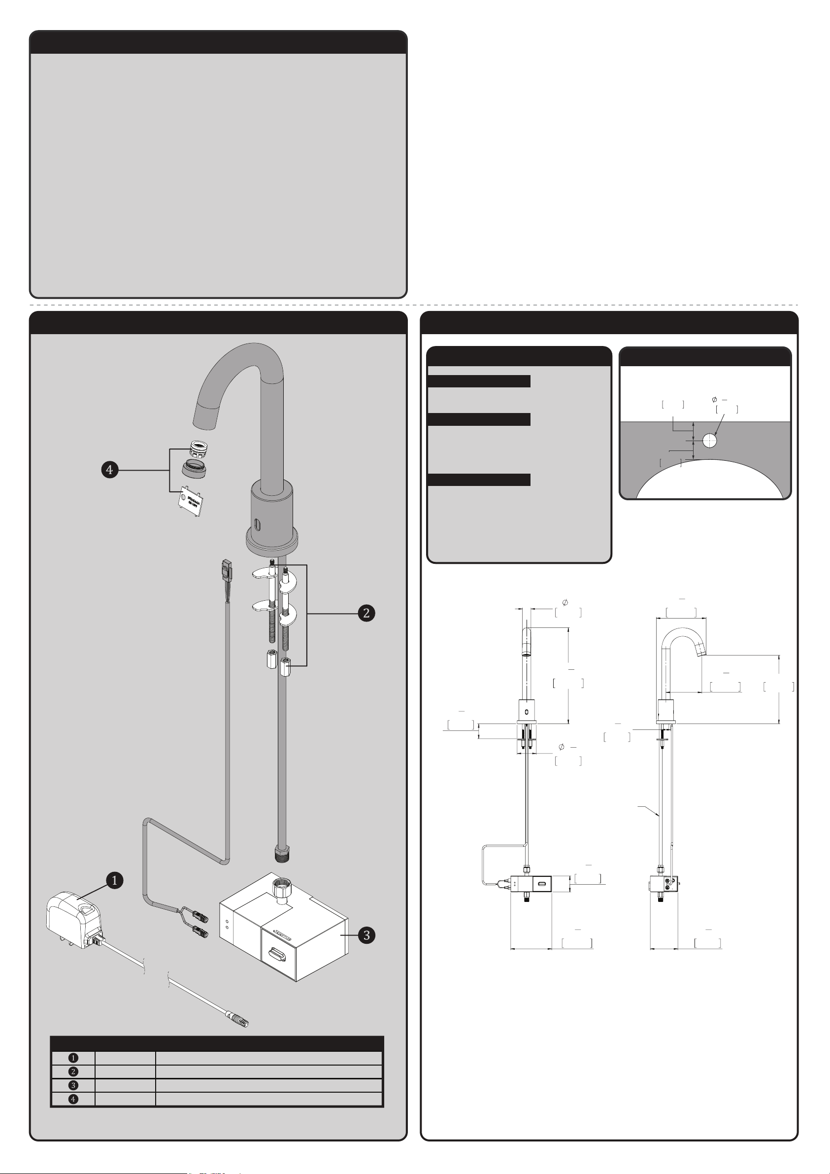
SF-9100 / SF-9200 REPAIR PARTS
SPEAKMAN
®
ITEM NO. PART NO. DESCRIPTION
RPG76-107259 TRANSFORMER 120VAC TO 6VDC
RPG45-110196 MOUNTING HARDWARE GROUP
RPG76-108060 SOLENOID ASSEMBLY (NO BATTERY)
RPG05-108059 0.5 GPM AERATOR REPAIR KIT
NOTES:
COMPLIANCE:
CONNECTIONS:
ASME A112.18.1/CSA B 125.1
Supply Connection:
9/16"-24 UNF Connection
FLOW DATA:
• 0.5gpm (1.9 L/min)
2"
MIN. TO LEDGE
51mm
2"
MIN. TO WALL
51mm
LAVATORY ROUGH-IN
29mm
1
1
8
"
MIN
SF-9100 / SF-9200 ROUGH-IN DIAGRAM
SPEAKMAN
®
ALL DIMENSIONS ARE IN INCHES (MILLIMETERS) UNLESS
OTHERWISE SPECIFIED. DIMENSIONS SUBJECT TO
CHANGE WITHOUT NOTICE.
SF-9100 / SF-9200 CARE AND CLEANING
1) Your SENSORFLO® Faucet is designed and engineered in accordance with the highest
quality and performance standards. With proper care, it will provide years of hygienic
and trouble-free service.
2) Periodically, the Faucet will require some minor maintenance to keep it at peak
performance. There are 2 low battery indicator lights. One located on the Sensor on the
Faucet body and the other located on the Solenoid Box. When the low battery light on the
Sensor blinks, it indicates that the battery is low. However, the Solenoid can still function
at this point. When the low battery light on the Solenoid blinks, the Solenoid will stop
functioning at this point and the batteries need to be replaced immediately. To replace the
batteries, follow the installation instructions in the electrical connections section of this
document.
3) The polished chrome finish of your Faucet should be cleaned using mild soap and
warm water.
4) Dry immediately with a soft, clean cloth for best results.
5) NEVER use abrasive cleaners, chemicals, alcohol or other solvents. They may damage
the surfaces of the non-chrome plated finishes.
7
5
1"
25mm
"
8
148mm
ACCOMODATES
3
1
"
4
44mm
DECK THICKNESS
1
11
4
285mm
1
2
4
57mm
4
122mm
"
FAUCET FITS
29mm
"
HOLE
24" SOLENOID
HOSE
7
1
"
8
48mm
3
"
4
1
4
"
4
107mm
1
1
"
8
1
3
"
4
82mm
8"
204mm
Page 4
INSTRUCTIONS FOR MODELS
92-G04-111563-01
For additional assistance or service please contact:
SPEAKMAN
®
800-537-2107
www.speakman.com
G04-111563
STAND ALONE MANUAL OVERRIDE
* MODEL SHOWN WITH SPEAKMAN SF-9100
GOOSENECK SENSOR FAUCET. WHILE YOUR
PRODUCTS MAY DIFFER IN APPEARANCE TO ITEM
SHOWN, IT WILL INSTALL WITH IN THE SAME
MANNER.
TOOLS AND SUPPLIES
Phillips
Screwdriver
Adjustable
Wrench
5 Gallon
Bucket
Warranty information can be found at:
www.speakman.com
WARRANTY
MAINTENANCE
Cover your drain to prevent loss of parts. Be sure to
wear eye protection while cutting pipe.
SAFETY TIPS
IMPORTANT
• Be sure to read instructions thoroughly before
beginning installation.
• Do not over-tighten any connections or damage
may occur.
Your new Speakman Product is designed for years of
trouble-free performance. Keep it looking new by
cleaning it periodically with a soft cloth. The use of harsh
chemicals and abrasives may damage the finish and
void the product warranty. Please be sure to only use
approved cleaners. Please contact Speakman for any
clarification of acceptable cleaners.
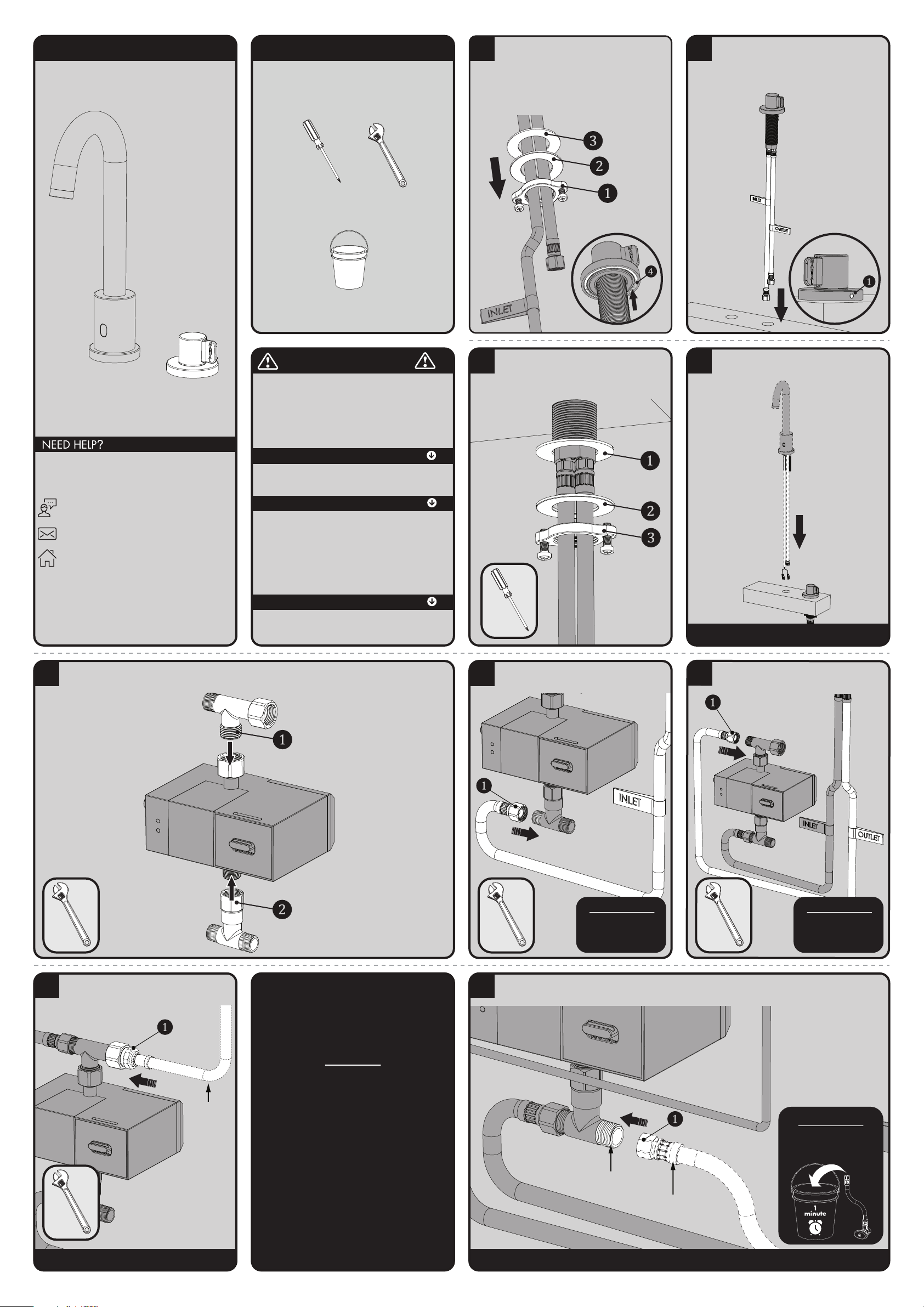
1
Remove Mounting Nut (1), Metal Washer (2),
and Rubber Washer (3) from Manual Override
Valve Assembly and slide them down to the
base of the Hoses. Then pull the Hose Ends
through one at a time. Verify that the Rubber
Gasket (4) is in position and aligned to the
base of the Valve Assembly.
2
Place Manual Override hoses thru the
appropriate hole in the counter top one at a
time. Align the valve assembly so the Rubber
Access Plug (1) is facing the rear and install
Valve Assembly through mounting hole.
3
From below, reinstall the Rubber Washer (1),
Metal Washer (2), and Mounting Nut (3). Hand
tighten until snug. Final tighten by using a Phillips
Screwdriver to turn each screw clockwise.
4
Install the Sensor Faucet onto the desired mounting
surface following the Faucet Installation Guide.
SHOWN WITH SPEAKMAN SF-9100
GOOSENECK SENSOR FAUCET.
5
Verify that all Rubber Seals are present in the swivel connections. Connect Tee #1(with check) (1) on the
“OUTLET” of the Solenoid Box. Then connect Tee #2 (without check) (2) to the “INLET” of the Solenoid Box.
INLET
TEE #2
TEE #1
OUTLET
6
Connect the Manual Override "INLET" Hose to
Tee #2. Wrench Tighten.
IMPORTANT
Dry Connection Only!
Do not use any
sealant on this
connection.
7
Connect the Manual Override "OUTLET" Hose to
Tee #1. Wrench Tighten
IMPORTANT
Dry Connection Only!
Do not use any
sealant on this
connection.
8
Connect the Faucet Inlet Hose (1) from your
Sensor Faucet model to the Swivel Nut on Tee #1.
SHOWN WITH SPEAKMAN SF-9100
GOOSENECK SENSOR FAUCET.
FAUCET
INLET
HOSE
NOTE:
Complete Mounting
and Electrical
Connections of the
Solenoid Box following
the Installation Manual
included with your
Sensor Faucet.
9
Flush the supply line for 1 min. then connect the Cold/Mixed Water Inlet (not supplied) (1) to Tee #2.
Wrench tighten all connections.
SHOWN WITH SPEAKMAN SF-9100 GOOSENECK SENSOR FAUCET.
IMPORTANT
Flush Inlet Water Supply
Line into a Bucket for 1
Minute prior to making
connection.
INLET WATER
SUPPLY LINE
9/16-24 UNEF
Page 5
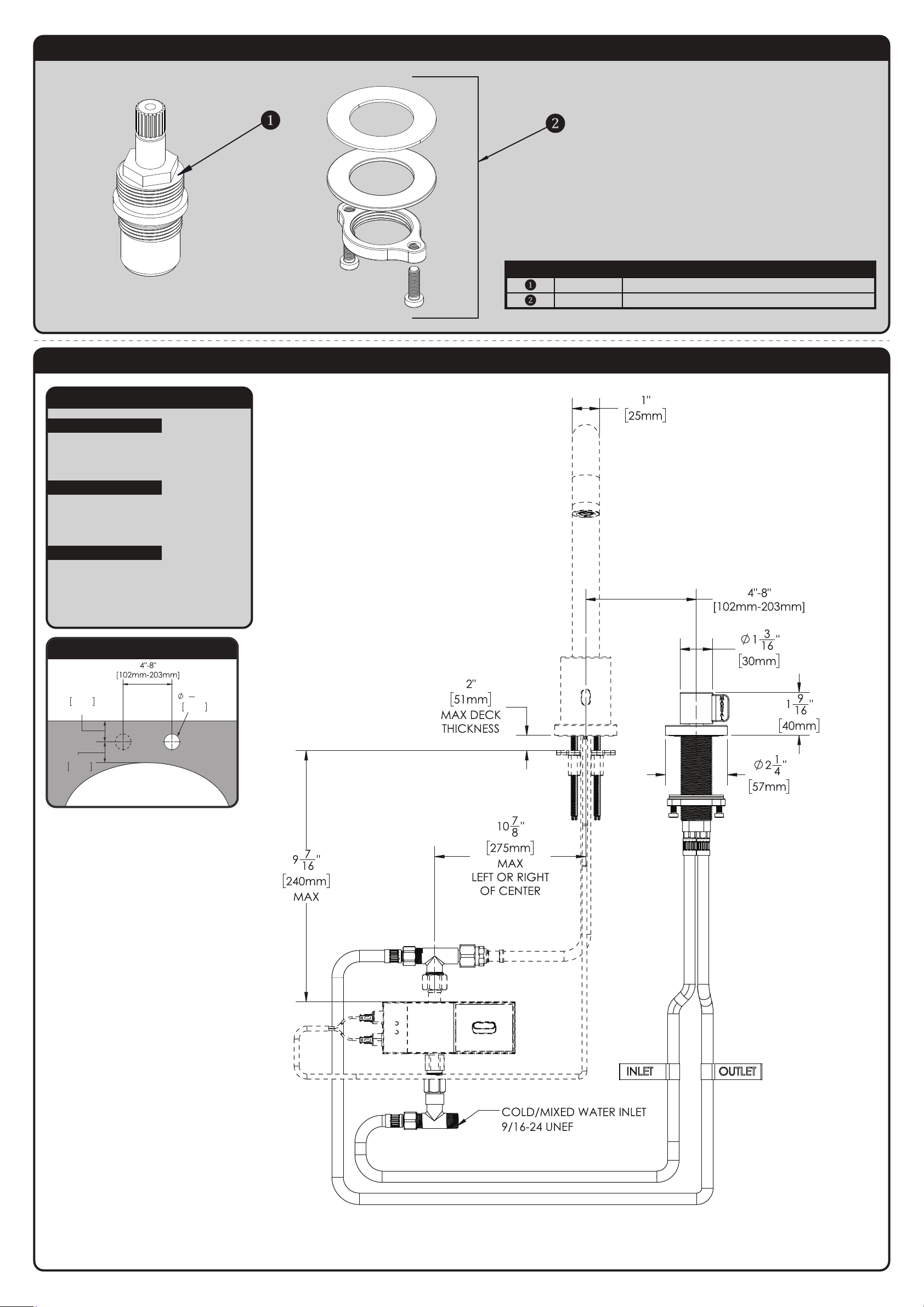
G04-111563 REPAIR PARTS
SPEAKMAN
®
ITEM NO. PART NO. DESCRIPTION
RPG05-106851 CARTRIDGE ASSEMBLY, BLUE
RPG05-112184 MANUAL OVERRIDE MOUNTING HARDWARE GROUP
G04-111563 ROUGH-IN DIAGRAM
SPEAKMAN
®
ALL DIMENSIONS ARE IN INCHES (MILLIMETERS) UNLESS
OTHERWISE SPECIFIED. DIMENSIONS SUBJECT TO
CHANGE WITHOUT NOTICE.
2"
MIN. TO LEDGE
51mm
2"
MIN. TO WALL
51mm
LAVATORY ROUGH-IN
29mm
1
1
8
"
MIN
NOTES:
COMPLIANCE:
CONNECTIONS:
ASME A112.8.1/CSA B 125.1
NSF372
NSF61
Supply Connection:
9/16"-24 UNF Connection
Contractor to supply necessary inlet
connections.
FLOW DATA:
• DETERMINED BY FAUCET MODEL.
REFER TO INSTRUCTION MANUAL
OF YOUR FAUCET MODEL.
 Loading...