

Page 1
INSTRUCTIONS FOR MODELS
92-SE-4330-01
For additional assistance or service please contact:
SPEAKMAN
®
Company
400 Anchor Mill Road
New Castle, DE 19720
800-537-2107
www.speakman.com
SE-4330
GRAVITYFLO
™
Portable Eyewash
with Heated Jacket
HELPFUL TOOLS & SUPPLIES:
TOOLS AND SUPPLIES
Flat Tip
Screwdriver
Adjustable
Wrench
Socket
Wrench
Phillips
Screwdriver
Pencil Level
Drill Drill Bit
Measuring
Tape
Safety
Glasses
Slip Joint
Wrench
3 Year Limited Warranty
1 Year on the Control Unit/pads/jacket
Additional warranty information can be found at:
www.speakman.com
WARRANTY
Be sure to wear eye protection.
SAFETY TIPS
IMPORTANT
Product is designed to be used indoorsProduct is designed to be used indoors
and outdoors.and outdoors.
When mounted in outdoor conditions, product must be When mounted in outdoor conditions, product must be
in a covered area and not directly exposed to outdoor in a covered area and not directly exposed to outdoor
elements such as rain and snow.elements such as rain and snow.
ANSI Z358.1 requires that all self-contained eyewash
shall be visually inspected weekly, unless the product
is placed in environments with extreme conditions that
may affect the form, fit, or function of the unit
(temperature, dirt, etc.). If this is the case, then the
inspection should be conducted more often as the end
user deems necessary. Speakman Company furnishes
a testing record tag (91-0635) with each unit. On this
tag, the date of inspection and the inspectors’ initials
should be noted. ANSI Z358.1 specifies that the
height of the spray heads is to be between 33” - 45”
from the floor. The SE-4330 unit weighs approximately
185 lbs filled. Ensure the mounting surface (wall, etc.)
and mounting hardware can safely hold a minimum
vertical load of 300 lbs. Be sure to read instructions
thoroughly before beginning installation. Do not
overtighten any connections or damage may occur.
The unit should be full at all times, to achieve the
minimum 15 minute run time as stated by ANSI, in
case of an emergency. Refill the tank to a full level
after each activation. Before refilling tank dry and
clean outside of spray heads, and inside of pull strap
to remove debris, and to assure proper sealing.
WARNING: This units maintains the water
1
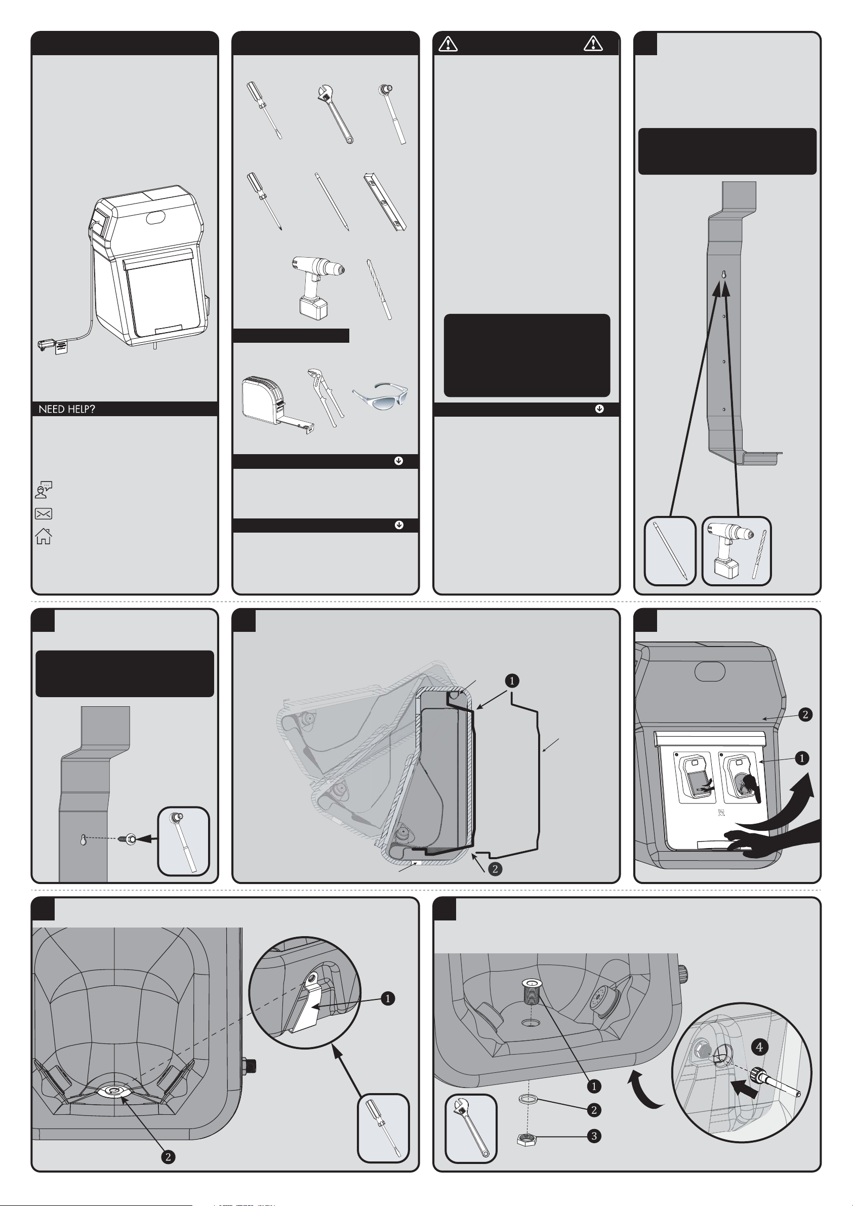
Select a suitable location for the SE-4330.
When mounted in outdoor conditions, product
must be must be in a covered area and not directly in a covered area and not directly
exposed to outdoor elements such as rain and exposed to outdoor elements such as rain and
snow.snow. After confirming the Spray Head height,
refer to the rough-in diagram for Wall Bracket
height measurements to determine mounting hole
locations for the bracket. Making sure the
bracket is level, mark and drill holes in the
mounting structure.
Note: Mounting hardware not included. Ensure
the mounting surface (wall, etc.) and mounting
hardware can safely hold a minimum vertical
load of 300 lbs.
2
Mount the Wall Bracket using appropriate
hardware, making sure to torque to
manufacturer’s specifications, if applicable.
Note: Mounting hardware not included. Ensure
the mounting surface (wall, etc.) and mounting
hardware can safely hold a minimum vertical
load of 300 lbs.
3
Install empty Tank to Wall Bracket by first inserting “hook” on the top of the bracket through the
Jacket Slot located at the upper rear of jacket and into the handle of the Tank (1). Lower the Tank
inserting the lower bracket section through the Jacket Slot and under the Tank. Push the Tank
towards the bracket until the Wall Bracket snaps into the recess at the bottom of the Tank (2).
*CROSS SECTION VIEW
HANDLE
WALL
BRACKET
DRAIN
4
CERTIFIED TO ANSI/ISEA Z358.1
Remove the Front Access Panel (1) from
the Jacket (2).
5
Use a flat head screw driver to ensure that the Bracket (1) and the tank's Drain Hole (2) align. The
Front Access Panel will need to be removed for this process.
* VIEW FROM
UNDER THE TANK
6
Insert Drain Fitting (1) through openings in the Tank and Wall Bracket. From below, reaching
between the Jacket and the Tank, install Drain Washer (2) and Drain Nut (3) to threaded portion
of Drain. Wrench tighten. Take care to not over tighten or damage may occur. Retrieve Drain
Hose (4) from parts accessory bag. Slide threaded Drain Hose (4) through hole in Jacket bottom
and secure to Drain Fitting (1). Hand tighten only.
* VIEW FROM UNDER THE TANK
temperature within the tepid range of 60-90 F.
Depending on the water temperature within the tank
and the ambient conditions, it may take up to
24 hours for the water temperature to reach the
tepid range during initial start-up. If noted during
inspection the water temperature is outside that
range, the product should be taken out of service
and the condition troubleshooted.
MAINTENANCE
Always disconnect power while servicing the unit and
allow the unit to cool down before filling with water.
Occasional cleaning and disinfection is recommended.
To clean the inside of the unit, add 1/2 cup (4 fluid
oz.) of Clorox (liquid bleach) to a full tank of potable
water. Allow the mixture to penetrate for 15 minutes.
Drain tank, and rinse thoroughly several times with
potable water. Take care to not overtighten drain cap
as damage may occur. For further information about
Clorox, call toll-free at 1-800-292-2200. Follow
refilling instructions in this manual and place the tank
back in service. Should any repair part be required,
use only genuine SPEAKMAN parts for repair or
replacement. See available replacement parts in this
document, to order parts call 1-800-537-2107.
As part routine inspection, the unit shall be checked for
adequate water level. (Within 5" of the top cap)
Page 2
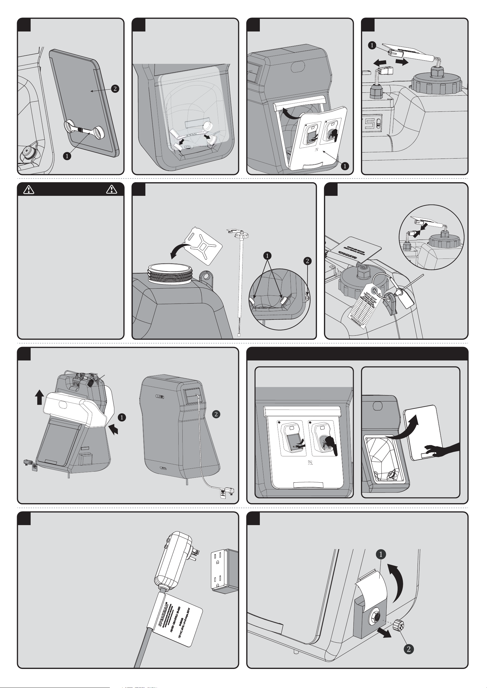
7
Retrieve the Activation Pull Strap (1) from
the accessory bag. Secure Activation Pull
Strap to backside of Front Access Panel (2)
as shown below using the Velcro straps.
8
Install the cups of the Activation Pull Strap
over the Spray Heads individually, pressing
firmly until they are fully seated. Ensure that
the Activation Pull Strap is still connected to
the Front Access Panel as shown in previous
step.
9
C
ERT
I
FI
E
D
T
O ANSI/I
SEA Z3
5
8.1
Realign front removable Panel (1) to Jacket
from the bottom up. Tuck the top edge of
the panel under the Jacket Flap.
10
Unzip upper portion of Jacket to fill Tank.
Disconnect Wiring Harness (1) from
Controller.
IMPORTANT
Self-contained eyewash equipment shall be visually
11
Remove Fill Cap in it’s entirety from the Tank. Do not damage any of the wires
upon removal. Fill the Tank with potable water (approximately 20 gallons).
Failure to use potable water can result in emergency units producing impure or
contaminated water, possibly causing further injury. Pull back top corner of
Activation Panel Flap and inspect Spray Head (1) area for leaks. Inspect Side
Drainage Plug (2) for leaks.
H20
12
Reinstall Fill Cap and secure it with the tamper-evident Seal
Tie. Reconnect Wiring Harness from STEP 10. Update and
secure the Maintenance Tag to the Tank in a location where
it can be easily checked.
13
Zip up open portion of Jacket (1). Verify all wiring is within Jacket and not kinked. Verify
AC Plug Adapter is fully extended through the Jacket (2). Velcro close the flap.
ACTIVATION INSTRUCTIONS
STEP 1: Follow instructions shown on the
front of the jacket Access Panel.
CERTIFIED TO ANSI/ISEA Z358.1
STEP 2: To activate the flow of water,
firmly remove the front panel as shown.
Fully removing both covers from the Spray
Heads.
14
Plug the unit into the power supply.
AC Electrical Supply
The Ground Fault Circuit Interrupter (GFCI) plug
is to be used in accordance with appropriate
electric codes and regulations. Use this device
with a grounded circuit receptacle rated at
120VAC, 15A.
The GFCI device protects against current
leakage caused by ground faults only. It does
not protect against over current or short circuits.
TEST INSTRUCTIONS
1. Plug device into receptacle.
a. AUTO-RESET devices: Pilot light goes ON.
2. Press test button – Pilot light must go OFF.
3. Press reset button and release – Pilot light
must go ON for use.
CAUTION: Do not use this device if above test
fails. Test unit before each use.
15
For Draining and Maintenance:For Draining and Maintenance:
To periodically drain the unit, Lift Flap (1) and velcro in place. Remove the Drain Plug (2). Once
all water is removed, reinstall the Drain Plug and hand tighten into position. Take care to not over
tighten or damage may occur.
See Maintenance Section for further detail.
checked frequently to determine if flushing fluid
needs to be changed or supplemented. Frequency
of these inspections is dependent on environment
conditions, but at a minimum weekly. Failure to
conduct visual checks could lead to further injury.
Customer shall take precautions to help prevent
the growth of potentially harmful bacteria in
eyewash tanks. Either of the following procedures
is recommended.
Procedure 1: Use suitable Bacteriostatic
preservative to help prevent growth of bacteria in
eyewash tank. Eyewash tank should be drained,
flushed and refilled with clean potable water and
Bacteriostatic preservative added as directed by
the preservative’s manufacturer.
Procedure 2: Drain, flush and refill units with
clean potable water at least once every week
unless site conditions require more frequent
changing. Thoroughly cleanse tank at least once
every month. See “Maintenance” Section for
further information of cleaning unit.
Page 3
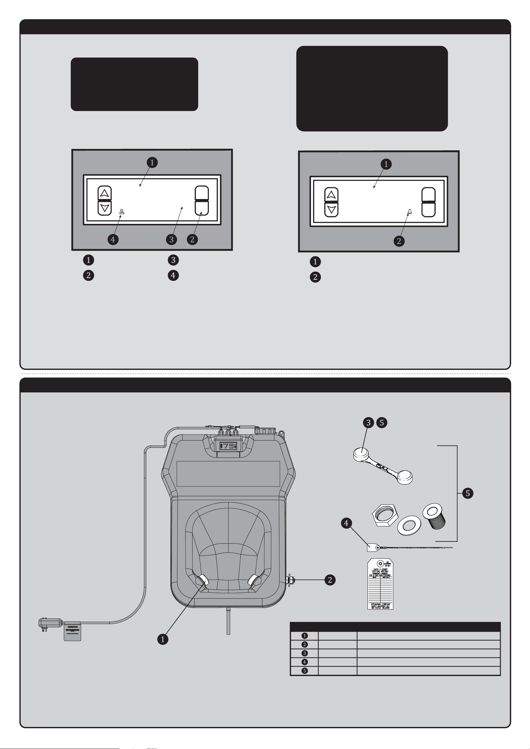
SE-4330 CONTROLLER INTERFACE
69.5
SE-4330 REPAIR PARTS
SPEAKMAN
®
RPG38-0433 (2) SPRAY HEAD ASSEMBLIES
08-105614 1/2" NPT MALE PLUG
RPG56-0039 PULL STRAP ACTIVATOR
RPG05-0935 (3) 12" TAMPER EVIDENT SEAL TIES
RPG05-0901 PULL STRAP ACTIVATOR & DRAIN BULKHEAD FITTING
ITEM NO. PART NO. DESCRIPTION
Heater Temperature Controller Model ED330
SPEAKMAN
®
* CONTROLLER SETTINGS ARE PRE-SET FROM FACTORY *
NOTE: During initial startup, the water temperature may
not be in the tepid range (60-90 F). Once plugged in, the
heating unit will warm the temperature up to the tepid
range. Depending on the water temperature within the
tank and the ambient conditions, it may take up to 24
hours for the water temperature to reach the tepid range.
NORMAL DISPLAY MODE
°F
SET
AC Electrical Supply
The Ground Fault Circuit Interrupter (GFCI) plug is to be used in
accordance with appropriate electric codes and regulations. Use this
device with a grounded circuit receptacle rated at 120VAC, 15A.
The GFCI device protects against current leakage caused by ground
faults only. It does not protect against over current or short circuits.
TEST INSTRUCTIONS
1. Plug device into receptacle.
a. AUTO-RESET devices: Pilot light goes on.
2. Press test button – Pilot light must go off.
3. Press reset button and release – Pilot light must go ON for use.
CAUTION: Do not use this device if above test fails. Test unit before
each use.
FAILURE MODE
°F
LL
SET
Default Settings:
SET Point = 75° F
Lower Limit = 60° F
Upper Limit = 90° F
Turn unit on: Current / Actual water temperature
will be displayed (1).
Temperature units to be in Fahrenheit (°F) (3).
Heating function indicator displayed means heater
is on (4).
CURRENT WATER TEMPERATURE
TEMPERATURE SET BUTTON
TEMPERATURE UNITS
HEATER ON INDICATOR
FAILURE INDICATOR DISPLAY
FLASHING ALARM INDICATOR
When the thermostat is disconnected or open
circuit is detected, “LL” (1) is displayed and alarm
LED (2) will flash.
TROUBLESHOOT
Confirm wiring connectors from heater pad to
controller are mated properly.
Confirm wiring connectors from thermostat to
controller are mated properly.
Page 4
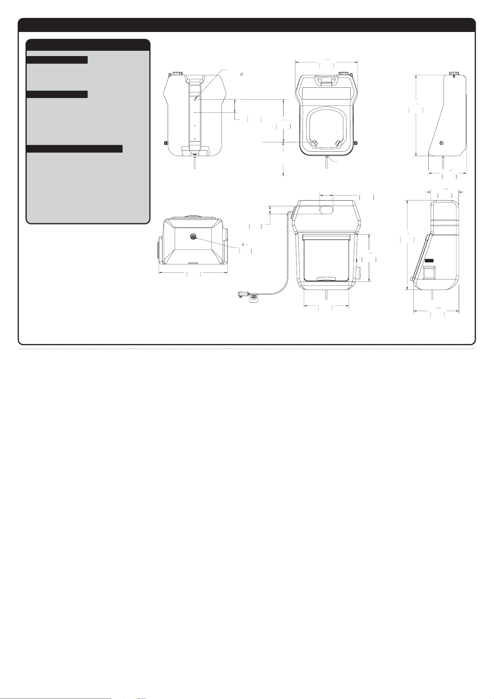
SE-4330 ROUGH-IN DIAGRAM
SPEAKMAN
®
DIMENSIONS SUBJECT TO CHANGE WITHOUT NOTICE.
NOTES:
COMPLIANCE:
FLOW DATA:
ANSI Z358.1
MAX ELECTRICAL RATINGS:
120VAC, 60Hz.
15A, 220W
RUN TIME (FULL TANK):
15 MINUTES (minimum)
FLOW RATE IN gpm (L/min):
.4 (1.5) MINIMUM
Contractor to supply necessary inlet
connections.
3"
76mm
17"
432mm
17
7
8
"
455mm
5"
127mm
33
7
8
"
861mm
10
9
16
"
269mm
17
3
16
"
436mm
3
4
"
18mm
26"
660mm
23
11
16
"
602mm
3/4in GHT MALE DRAIN OUTLET
(UNDERSIDE OF TANK)
33-45in
[833-1143mm]
TO FLOOR
5"
127mm
(TYP. 3 PLACES)
16
3
16
"
411mm
WALL BRACKET MOUNTING
HOLES
1/4" THRU HOLE
(TYP. 4 PLACES)
30
5
8
"
777mm
14
3
8
"
365mm
 Loading...