

Page 1
INSTRUCTIONS FOR MODELS
SC-3044-LD
SC-3044-LD-E
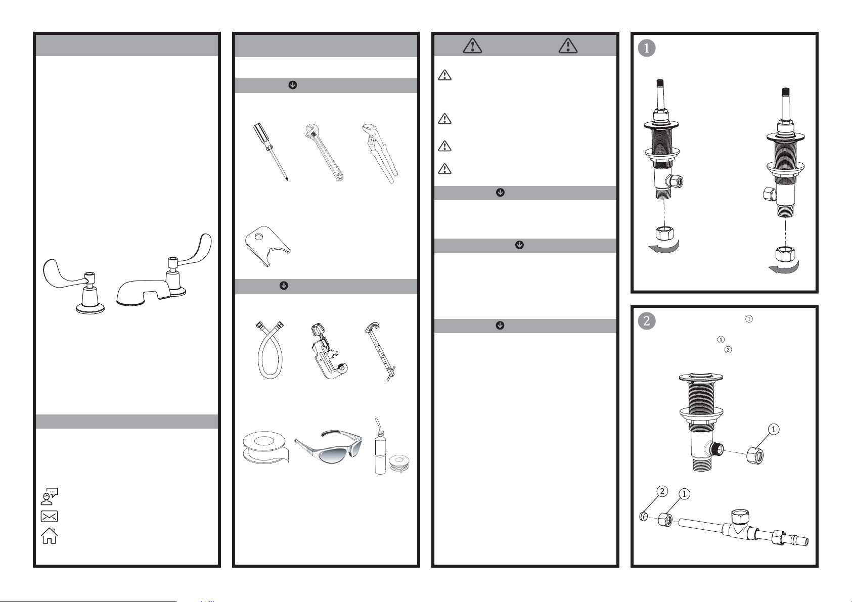
TOOLS AND SUPPLIES
REQUIRED
Phillips
Screwdriver
Adjustable
Wrench
Slip Joint
Wrench
IMPORTANT
This installation manual covers several models.
While the appearance of your faucet may vary, the
installation steps required are the same as shown in
this manual.
Be sure to read instructions thoroughly before
beginning installation.
Do not overtighten any connections or damage
may occur.
This faucet has an operating range of 20-80 psi.
Remove the Compression Nuts from the inlets
of the end body valves.
NEED HELP?
For additional assistance or service please contact:
SPEAKMAN
400 Anchor Mill Road
New Castle, DE 19720
®
Company
Aerator
Wrench
(supplied)
HELPFUL
Supply
Hoses
Thread Seal
Tape
Tubin g
Cutter
Safety
Glasses
Basin
Wrench
Solder
Kit
SAFETY TIPS
Cover your drain to prevent loss of parts. Be sure to
wear eye protection while cutting pipe.
MAINTENANCE
Your new Lavatory Faucet is designed for years of
trouble-free performance. Keep it looking new by
cleaning it periodically with a soft cloth. Avoid
abrasive cleaners, steel wool, and harsh chemicals
as these will dull the finish and void your warranty.
WARRANTY
Additional warranty information can be found at:
www.speakman.com
Remove Compression Nuts from End Bodies.
Retrieve the Tee Assembly bag group. Slide a
Compression Nut , followed by a
Compression Sleeve over the copper pipe of
each end of the Tee Assembly.
800-537-2107
www.speakman.com
92-SC-3044-LD-R2
Page 2
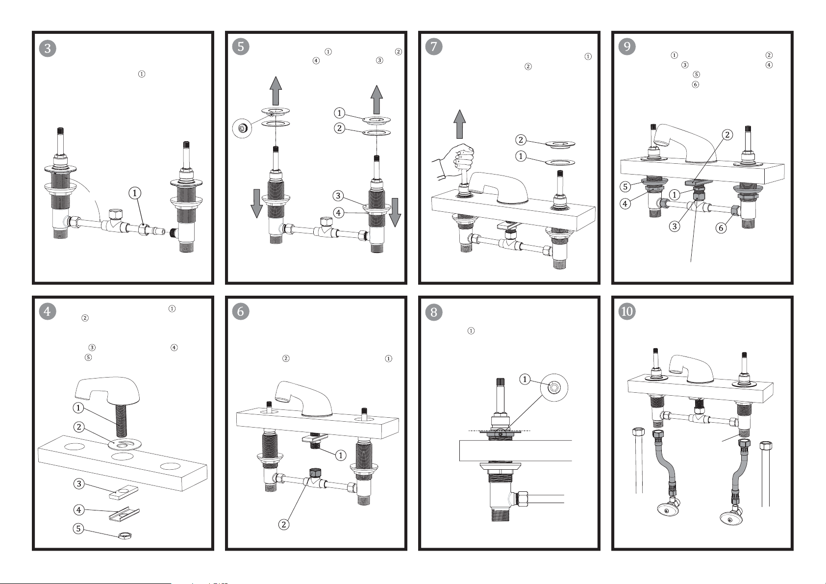
Bench assemble the Tee to the HOT and COLD
end body valves. Be sure to fully seat the copper
piping into the end body valves, and hand
tighten Compression Nuts to the outlet ports.
Be sure the end body valves are perpendicular
to the Tee assembly.
90°
Loosen the set screws and remove the end
body valve flange nuts and rubber washers
Screw the locknuts and cup washers
down on end body valves.
While lifting the end body with tee assembly
up by its spindles, replace the rubber washers
and screw the flange nuts back onto the end
body valves, with flat side up, till they are flush
with the tops of the 1-1/8”-16 UN threads of
the end body valves.
From below, wrench tighten the shank
flange nut with channel washer/spacer ,
tee swivel nut , end body valve locknuts
with cup washers , and two (2) tee
compression nuts at the outlets of the end
body valves to secure the entire unit and
prevent leaks.
NOTE: Do Not Overtighten Swivel Nut
Insert and position the Center Spout with
gasket down through the center hole of the
sink or counter top, being sure the cut out of the
gasket is aligned to the rear of the faucet. Assemble
Rubber Washer , Metal Channel Washer and
Mounting Nut to shank and thread only half way
up the shank.
From below the counter top, push the end body
with tee assembly up through the outer holes in
the sink or counter top. NOTE: Blue colored
end body (COLD) should be on the right side
of tee assembly, Red colored end body (HOT)
on the left. Hand tighten the tee assembly’s
swivel nut to the shank of the center spout
RED
(HOT)
BLUE
(COLD)
Ensure the Flange Nuts are flush with the tops
of the 1-1/8”-16 UN threads, then tighten set
screws .
Connect water supply lines to inlets (1/2”-14
NPSM male threads) of the end body valves
and wrench tighten coupling nuts to prevent
leaks.
1/2”-14 NPSM
NOTE: Flex Hoses and Shut Off Valves not included.
Page 3
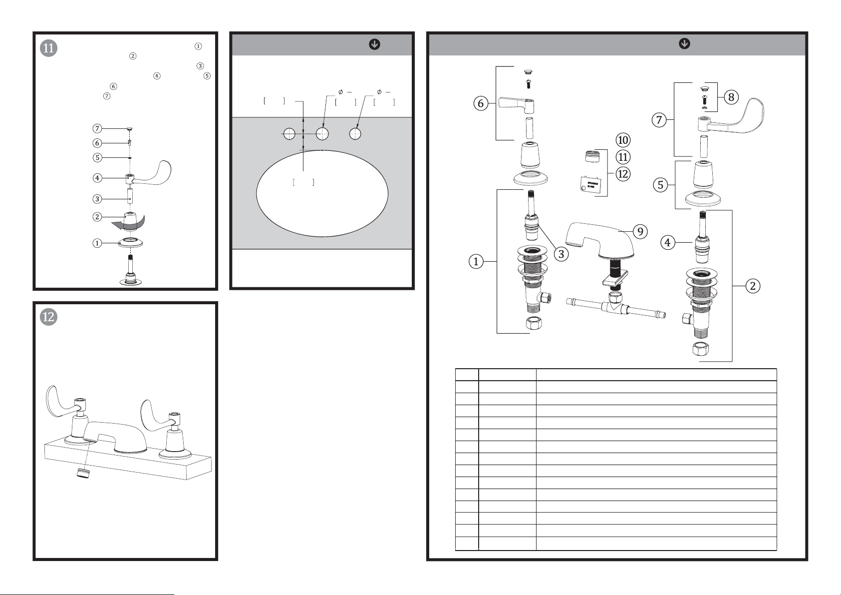
From above the sink, place decorative flange ,
then screw escutcheon onto end body valve
assemblies and hand tighten. Slip trim sleeves
onto spindles. Position handles , lock washers
and use screws to secure to spindles. Position
index buttons on handles (blue on right
handle, red on left handle) and press into place.
Turn on water supplies and flush both HOT and
COLD cartridges for one minute, while checking
for leaks. Once completed, install aerator into
spout end using supplied aerator wrench.
LAVATORY ROUGH IN
1
"
2"
51mm
MIN. TO WALL
MIN. TO LEDGE
2"
51mm
1
38mm
2
1
35mm
REPAIR PART GROUPS
3
"
8
⑬
⑭
ITEM PART NUMBER DESCRIPTION
1 RPG20-2011-CA END BODY ASSEMBLY (RED) W/ MOUNTING HARDWARE & HOSE ADAPTER
2 RPG20-2012-CA END BODY ASSEMBLY (BLUE) W/ MOUNTING HARDWARE & HOSE ADAPTER
3 RPG05-0534-CA PERFECT VALVE GROUP (RED) WITH TRIM SLEEVE & SCREW
4 RPG05-0535-CA PERFECT VALVE GROUP (BLUE) WITH TRIM SLEEVE & SCREW
5 RPG10-0070-PC TRIM COLLAR & FLANGE GROUP
6 RPG04-0320-PC METAL LEVER HANDLE GROUP
7 RPG04-0316-PC 4" WRIST BLADE HANDLE GROUP
8 RPG41-0285 RED,BLUE, & CHROME INDEXES WITH SCREWS & LOCK WASHERS
9 G18-0251-CA CENTER SPOUT ASSEMBLY (LESS LIFT ROD HOLE)
RPG05-0837-PC 1.5 GPM (5.7 L/min) AERATOR ASSEMBLY WITH WRENCH
10
RPG38-0128-PC BOCA FLOW OUTLET ASSEMBLY WITH WRENCH
11
RPG05-0851-PC 1.5 GPM (5.7 L/min) LAMINAR FLOW OUTLET ASSEMBLY WITH WRENCH
12
RPG05-40005 1.2 GPM (4.5 L/min) AERATOR ASSEMBLY WITH WRENCH
13
1.2 GPM (4.5 L/min) LAMINAR FLOW OUTLET ASSEMBLY WITH WRENCH14 RPG05-40015
Page 4
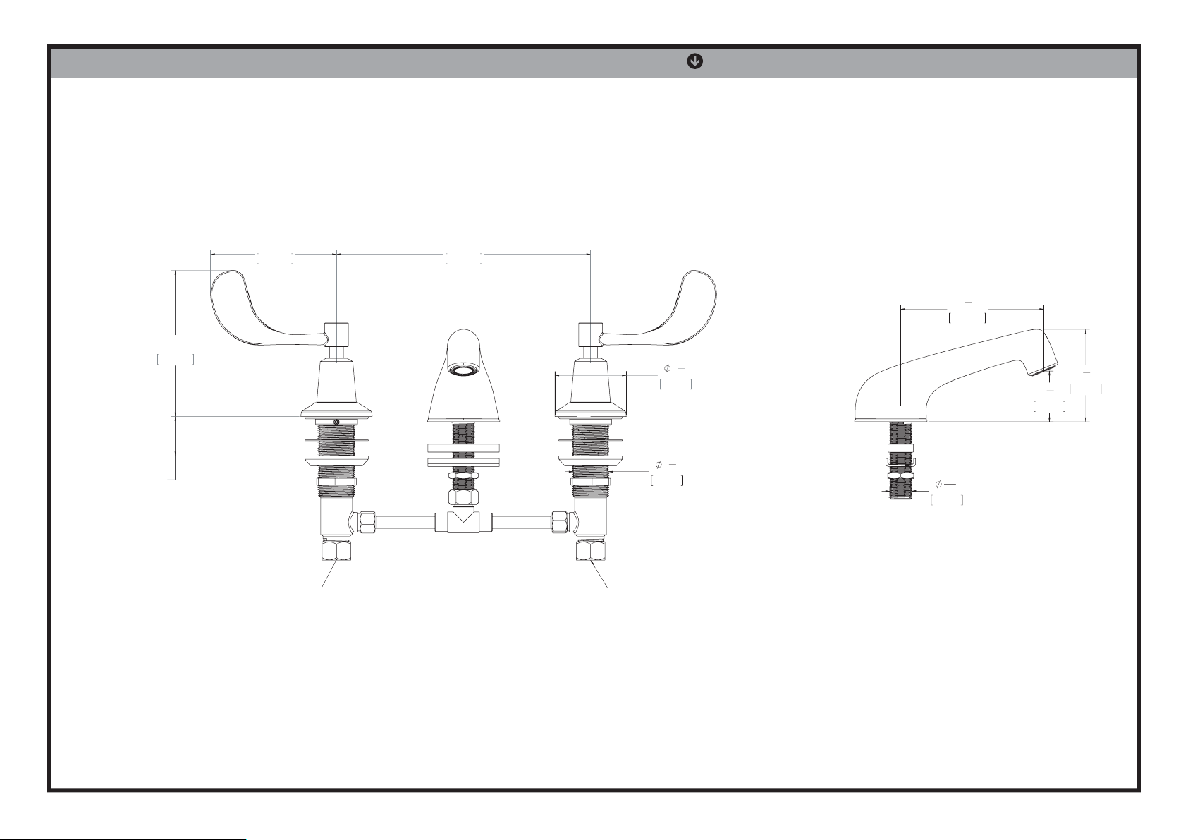
SC-3044-LD
ROUGH IN DIMENSIONS
1-1/2"
[38mm]
MAXIMUM
DECK THICKNESS
5
4
8
117mm
4"
101mm
"
HOT INLET
8"
203mm
29mm
COLD INLET
2
57mm
1
1
8
1
4
"
2
115mm
1
"
4
1
41mm
"
11
"
16
18mm
7
2
"
8
5
74mm
"
8
 Loading...