

Page 1
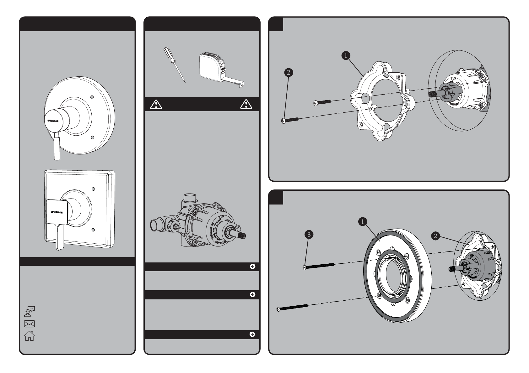
INSTRUCTIONS FOR MODELS
CPT-1000-TP
TOOLS AND SUPPLIES
1
Clean front surface of wall. Install Valve Mounting Plate (1) to Speakman Valve, using the 8-32 x
1-1/8” screws (2) provided. Take care to not over tighten mounting screws.
NOTE: The Valve Mounting Plate Assembly (1) should sit flush against the Speakman Valve when
installed correctly.
2
NOTE: The back surface of the Valve Mounting Plate Assembly (1) should sit flush against the wall when
installed correctly.
Secure the Wall Mounting Plate (1) to the Valve Mounting Plate (2) using the 8-32 X 2½” Screws
(3) provided.
CPT-1300-TP
Phillips
Screwdriver
Measuring
Tape
IMPORTANT
• Circular Trim Package shown for reference. While
the appearance of your trim may be different, the
installation steps are the same.
• This Trim Package is intended to mount to the
following Speakman valve. Please verify the model
of your valve prior to installation.
SPEAKMAN
CPV-5000 Thermostatic / Balance Pressure Valve
*NOT FOR USE WITH DIVERTER/VOLUME CONTROL MODELS
NEED HELP?
For additional assistance or service please contact:
SPEAKMAN
400 Anchor Mill Road
New Castle, DE 19720
800-537-2107
www.speakmancompany.com
®
Company
92-CPT-1000-TP-R1
SAFETY TIPS
Cover your drain to prevent loss of parts. Be sure to
always wear proper eye protection.
MAINTENANCE
Your new Valve Trim is designed for years of
trouble-free performance. Keep it looking new by
cleaning it periodically with a soft cloth. Avoid
abrasive cleaners, steel wool, and harsh chemicals as
these will dull the finish and void your warranty.
WARRANTY
Additional warranty information can be found at:
www.speakmancompany.com
®
SentinelPro
®
Page 2
3
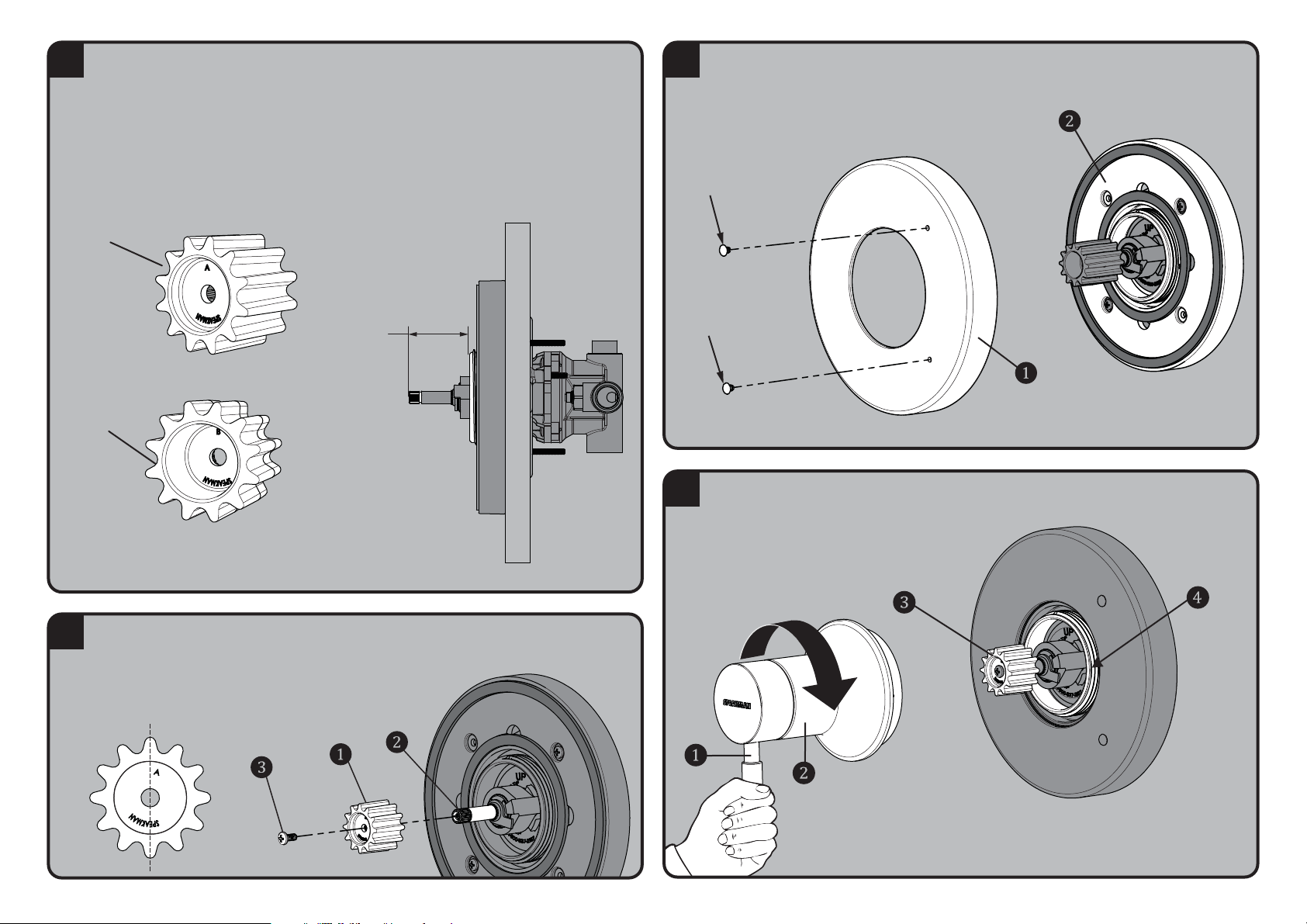
MEASURE
The Universal Valve Trim kit includes two Spindle Adapters that allow for both shallow and deep
valve mount installations. Measure the distance between the front lip of the Wall Mounting Plate
and the end of the Valve Spindle as shown below to determine correct selection of Spindle
Adapter.
• If the measurement falls between 1-7/8” to 2-1/2”, the Spline Adapter marked “A” is
needed for installation.
• If the measurement falls between 1-3/8” to 1-7/8”, the Spline Adapter marked “B” is
needed for installation.
A
B
4
VERTICAL
LINE
Confirm that the Valve is in the off position. Insert Spline Adapter (1) (Spline Adapter selection
determined in Step 3) over Valve Spindle (2). One set of splines on the adapter must be oriented
perfectly vertical when installed, as shown below. Secure the Spline Adapter with the 8-32 X 3/8”
Screw (3) provided.
5
RED
BLUE
Orient the Decorative Wall Plate (1) as shown below and insert the RED index button into the top
hole of the Wall Plate, and the BLUE index button into the lower hole. Slide Wall Plate Assembly
over Wall Mounting Plate (2).
6
Orient the Handle Assembly in a vertical position as shown below. Guide Handle Assembly onto
the Spline Adapter (3). While holding the Handle (1) stationary in the vertical position, thread the
Handle Escutcheon (2) onto the Wall Mounting Plate (4). Hand tighten until snug.
NOTE: This style of Valve uses a “Compression Stop”. After Handle Assembly
installation, rotate Handle clockwise to achieve full compression and closure of Valve.
If the Handle does not rest in a vertical position after full compression, repeat Steps 4
and 6 for proper Handle alignment.
Page 3
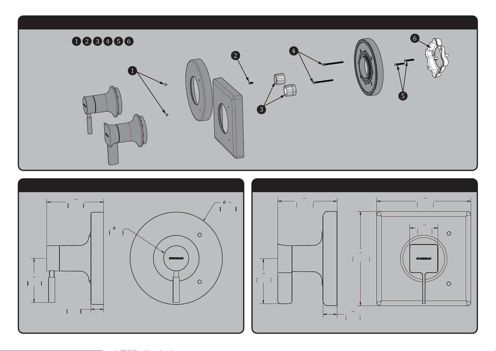
REPAIR PARTS
•RPG10-0118
ROUGH-IN DIMENSIONS: CPT-1000-TP
•Dimensions are subject to change without notice.
7
1
4
"
186mm
2"
51mm
4
1
2
"
114mm
3
1
2
"
89mm
1"
25mm
ROUGH-IN DIMENSIONS: CPT-1300-TP
•Dimensions are subject to change without notice.
7
1
4
"
186mm
7
1
4
"
186mm
2
1
4
"
56mm
3
1
2
"
89mm
4
5
8
"
117mm
1
1
8
"
28mm
 Loading...