

Page 1
INSTRUCTIONS FOR MODELS
OPTIMUS
™
SE-1200
SE-1250
SE-1255
STANDARD INSTALLATION
(FOR ADA INSTALLATION SEE PAGE 6)
NEED HELP?
For additional assistance or service please contact:
SPEAKMAN
400 Anchor Mill Road
New Castle, DE 19720
800-537-2107
www.speakmancompany.com
92-SE-1200-1255-R4
®
Company
TOOLS AND SUPPLIES
Level Adjustable
Wrench
7/16” Hex Key
Wrench
Strap
Wrench
Pipe
Wrench
Mounting
Hardware
(not included)
IMPORTANT
ANSI Z358.1 requires that all safety emergency
equipment shall be activated on a weekly basis to flush
the line and verify proper operation. SPEAKMAN
furnishes a testing record tag (91-0635) with each unit.
On this tag, the date of inspection and the inspector’s
initials should be noted. ANSI Z358.1 specifies that the
height of the spray heads is to be between 33” - 45”
from the floor. Use Thread Locker or Sealant on all
threaded connections. Be sure the Unit is level and
plum.
SAFETY TIPS
Cover your drain to prevent loss of parts. Always wear
eye protection.
MAINTENANCE
Should you need parts to repair this unit, please
reference the parts listing for correct repair part
number. Before any maintenance is done, be sure to
shut the water supply off. Use only genuine
SPEAKMAN parts when repairing or replacing
components. To order parts, call 1-800-537-2107.
WARRANTY
3 year limited warranty.
Additional warranty information can be found at:
www.speakmancompany.com
For ADA installation see Page 6.
Use Thread Locker or Sealant on ALL
threaded connections
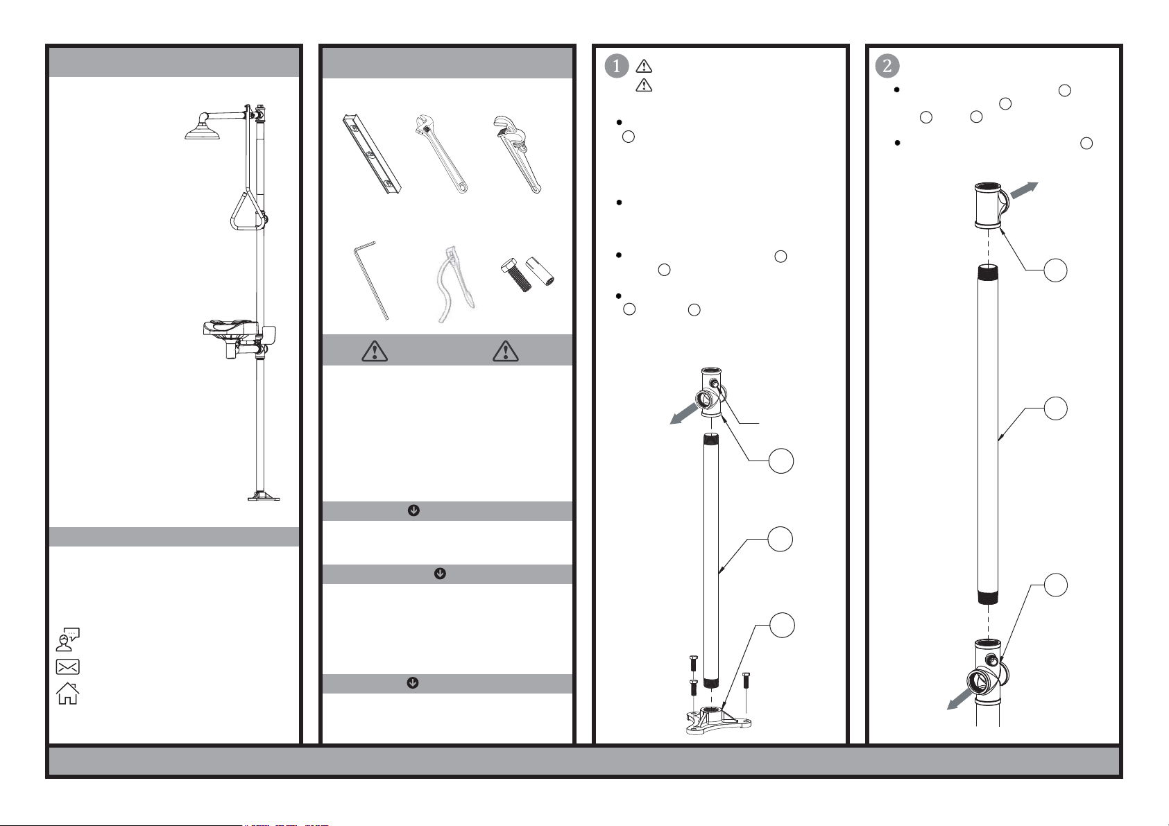
At desired location, mount Floor Flange
13
on a flat, level surface using suitable
anchors, making sure that one of the three
ears on the Floor Flange is positioned at
what will be the front of the Stanchion.
The Unit should be placed so that there is
sufficient unobstructed area around the
Stanchion.
Assemble
Flange .
Thread 1-1/4” x 1/2” Drain/Supply Cross
12
onto Pipe . Side Outlets should face
the front and back of the Unit, and the
1/2” male threaded outlet upward at 45°
to the right side of the Unit.
Front of Unit
1-1/4” x 32-3/8” Pipe to Floor
13
29
29
1/2” Male
Threading
12
29
13
Assemble 1-1/4” x 26-7/16” Pipe to
Drain/Supply Cross . Assemble
10
Tee to Pipe .
Assure the Side Outlet portion of Tee
is facing the rear of the Unit.
Front of Unit
12
11
11
1-1/4”
Rear of Unit
10
11
12
10
STANDARD INSTALLATION - FOR ADA INSTALLATION SEE PAGE 6 PG.1
Page 2
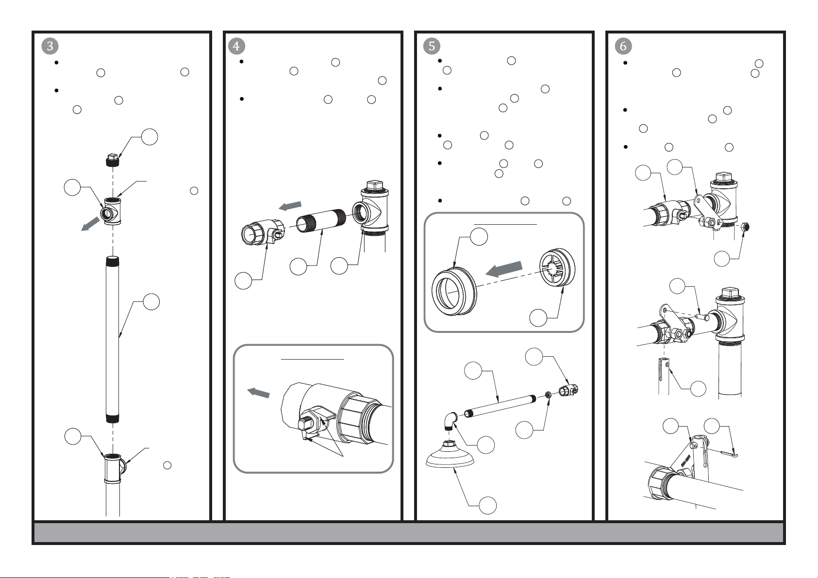
If water supply is coming from above Unit,
install Plug into side outlet of Tee .
7
If water supply is coming from behind
Unit, install Plug into top outlet of
8
Tee .
7
7
8
For Back Supply,
install Plug
here.
Front of Unit
Assemble 1” x 4-1/2” Pipe into Side
10
Outlet of Tee . Review View 4a below to
8
understand the orientation of Ball Valve .
6
5
Insert Flow Control into Floet Housing
3
, referring to Detail View 5a.
Insert Flow Control Assembly into end
1” x 17-5/8” Pipe , so that the flange
Assemble
1” Ball Valve onto Pipe .
5
6
Valve Stops must be aligned correctly in
order for the Pull Handle to operate
of
of Floet Housing is fully seated in the
end of Pipe.
properly.
Install Pipe with Flow Control Assembly
A
into Ball Valve .
Assemble Elbow to Pipe being sure
to orient Elbow so that the outlet is
4
2
3
2
5
1
1
A
2
Assemble the Lever Handle Assembly
to Ball Valve using Nylo-Hex Nut ,
5
being sure to orient the Handle as shown
below.
Insert the slot in the Pull Rod over the
Lever Handle Assembly and insert
18
Pin .
Secure Pin with Cotter Pin .
18
5
16
20
16
19
16
17
facing down.
7
To Showerhead
Assemble Showerhead to Elbow .
14
1
Detail View 5a
3
10
9
For Top Supply,
install Plug
7
here.
6
5
8
18
17
4
To Showerhead
Detail View 4a
2
5
20
A
18
19
1
Valve Stops
14
STANDARD INSTALLATION - FOR ADA INSTALLATION SEE PAGE 6 PG.2
Page 3
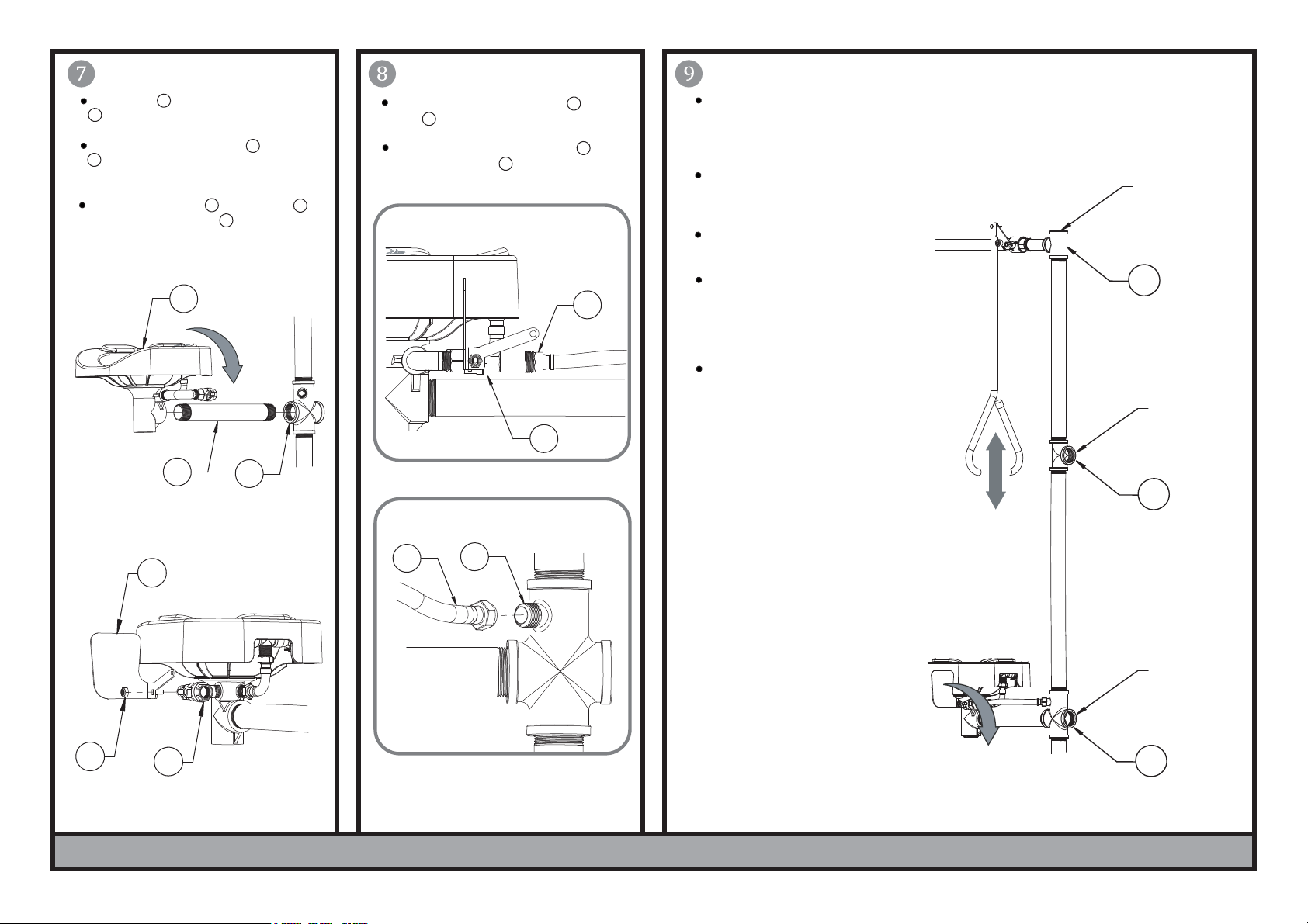
Thread Pipe into Drain/Supply Cross
12
.
Thread entire Bowl Assembly to Pipe
21
, being sure Bowl is level, plumb, and
horizontal when completely secured.
Install Paddle Handle to Ball Valve
using Nylo-Hex Nut Nut .
21
22
24
25
23
Assemble male end of Flex Hose to Ball
23
Valve (Detail View 8a).
Assemble female end of Flex Hose to
Drain/Supply Cross (Detail View 8b).
12
15
15
Detail View 8a
Connect an uninterruptible potable water
supply with a minimum of 30psi flowing
pressure to Water Inlet. Failure to use
potable water can result in further injury.
Connect an adequate drain to Drain
Outlet that complies with all local
plumbing codes.
Turn on water supply and check
connections for leaks.
Alternate
Water
Inlet
24
21
22
12
15
23
Detail View 8b
12
15
To test the Eye/Face Wash, and for
subsequent operation, push the Paddle
Handle forward 90°. The unit will operate
until the Paddle Handle is manually pulled
back to the OFF position.
To test the Shower, and for subsequent
operation, pull the Pull Rod down. The
unit will operate until the Pull Rod is
manually pushed back to the OFF position.
8
Standard
Water
Inlet
10
EMERGENCY
SHOWER
ACTIVATION
Drain Outlet
25
23
EYE/FACEWASH
12
ACTIVATION
STANDARD INSTALLATION - FOR ADA INSTALLATION SEE PAGE 6 PG.3
Page 4
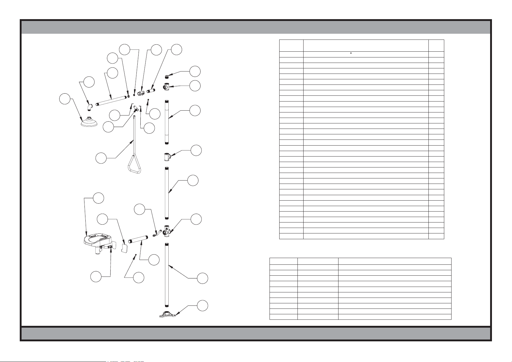
STANDARD INSTALLATION EXPLODED VIEW / REPAIR PART GROUPS
14
Item
46
5
3
2
1
19
16
17
18
7
8
9
10
20
11
22
15
24
12
No.
1
2
3
4
5.1
5.2
6
7
8
9
10
11
12
13
14
15
16.1
16.2
17
18
19
20.1
20.2
21
22
22.1
22.2
22.3
23
23.1
23.2
24
25
29
1" Chrome Plated Brass Ball Valve
1-1/4" x 22-1/4" Galv. Pipe, TBE
1-1/4" x 26-7/16" Galv. Pipe, TBE
1-1/4" x 1/2" Galv. Drain/Supply Cross
Stainless Steel Flexible Supply Hose
Lever Handle w/Spring Plunger (SE-1200/SE-1250)
Lever Handle w/Spring Plunger (SE-1255)
7/16-20 UNF Stainless Steel Nylo-Hex Nut
1-1/4" x 11-5/8" Galv. Pipe, TBE
Plastic Bowl, Chrome Plated Brass Ball Valve (SE-1
S/S Bowl, Chrome Plated Brass Ball Valve
S/S Bowl, Stainless Steel Ball Valve
1/2" Chrome Plated Brass Ball Valve (SE-1200/1250)
1/2" Stainless Steel Ball Valve (SE-1255)
3/8" Stainless Steel Nylo-Hex Nut
1-1/4" x 32-3/8" Galv. Pipe, TBE
Description
1" x 90
Galv. Street Elbow
1" x 19-3/8" Galv. Pipe, TBE
Rubber Floet Housing
20 GPM Flow Control
1" Stainless Steel Ball Valve
1" 4-1/2" Galv. Pipe, TBE
1-1/4" Galv. Plug
1-1/4" x 1-1/4" x 1" Galv. Tee
1-1/4" Galv. Tee
1-1/4" Galv. Floor Flange
8" Deluge Showerhead
Clevis Pin
Cotter Pin
29" Aluminum Pull Rod
29" Stainless Steel Pull Rod
Eyewash Unit
1/2" Ball Valve
Paddle Handle
Qty.
1
1
1
1
1
1
1
1
1
1
1
1
1
1
1
1
1
1
1
1
1
1
1
1
1
1
1
1
1
1
1
1
1
23
REPAIR PARTS
21
25
29
13
STANDARD INSTALLATION - FOR ADA INSTALLATION SEE PAGE 6 PG.4
Item No.
5
5
14
14
20.1
20.2
22.1
22.2
22.3
15
Part No.
SE-911
SE-911-SS
SE-870
SE-880
RPG47-0046
RPG47-0044
SE-1000
SE-1050 S/S Bowl, Chrome Plated Brass Ball Valve
SE-1055
RPG63-0094
1" Stainless Steel Ball Valve SE-1255 Only
Aluminum Pull Rod (With ADA Extension)
S/S Pull Rod (With ADA Extension)
PlasticBowl, Chrome Plated Brass Ball Valve
S/S Bowl, Stainless Steel Ball Valve (SE-1255 only)
Description
1" Ball Valve
8'' Plastic Showerhead
8'' Stainless Steel Showerhead
Stainless Steel Supply Hose
Page 5
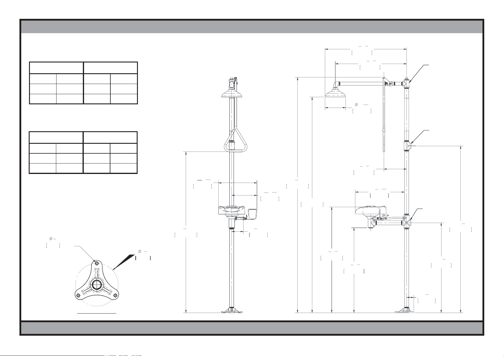
SE-1200/1250/1255
SHOWER FLOW DATA
PRESSURE
psi
30
60
bar
2.07
4.14
FLOW RATE
gpm
20
25
L/min
75
94
SE-1200/1250/1255
EYE/FACEWASH FLOW DATA
PRESSURE
psi
30
60
bar
2.07
4.14
NOTE: ALL UNITS MEET EXISTING ANSI Z358.1 STANDARDS
AND OSHA RULES. PRODUCT IMPROVEMENTS MAY CAUSE
SPECIFICATION AND DIMENSIONAL CHANGES WITHOUT
NOTICE.
1
"
2
13mm
(TYP. 3 PLACES EQUALLY
SPACED 120º APART)
FLOW RATE
gpm
4.9
5.0
L/min
18.5
18.9
7
200mm
7
"
8
STANDARD INSTALLATION ROUGH-IN DIMENSIONS
5
"±1"
62
8
1592mm±25
15
14
16
380mm±5
3
"±
"
16
3
13
"±
"
9
16
16
250mm±5
1
"±.19
4
2
116mm±5
5
"±1"
91
8
2329mm±25
2134mm±25
84"±1"
1
"±
41
8
1046mm±13
1
"
2
1
33
8
840mm±10
5
3
"±
31
8
4
806mm±16
27
705mm±19
1
8"±
16
203mm±2
7
"±
8
8
225mm±10
3
"±
"
8
"
3
"±
4
"
3
"
8
19
486mm±9
3
"
4
11
1
"±
"
32
8
1-1/4" NPT (TOP)
FEMALE INLET
1-1/4" NPT
FEMALE INLET
1-1/4 NPT
FEMALE OUTLET
35"±
890mm±10
1651mm±16
3
"
8
5
"
65"±
8
FLOOR FLANGE DETAIL
3
"
2
4
69.85mm
STANDARD INSTALLATION - FOR ADA INSTALLATION SEE PAGE 6 PG.5
Page 6
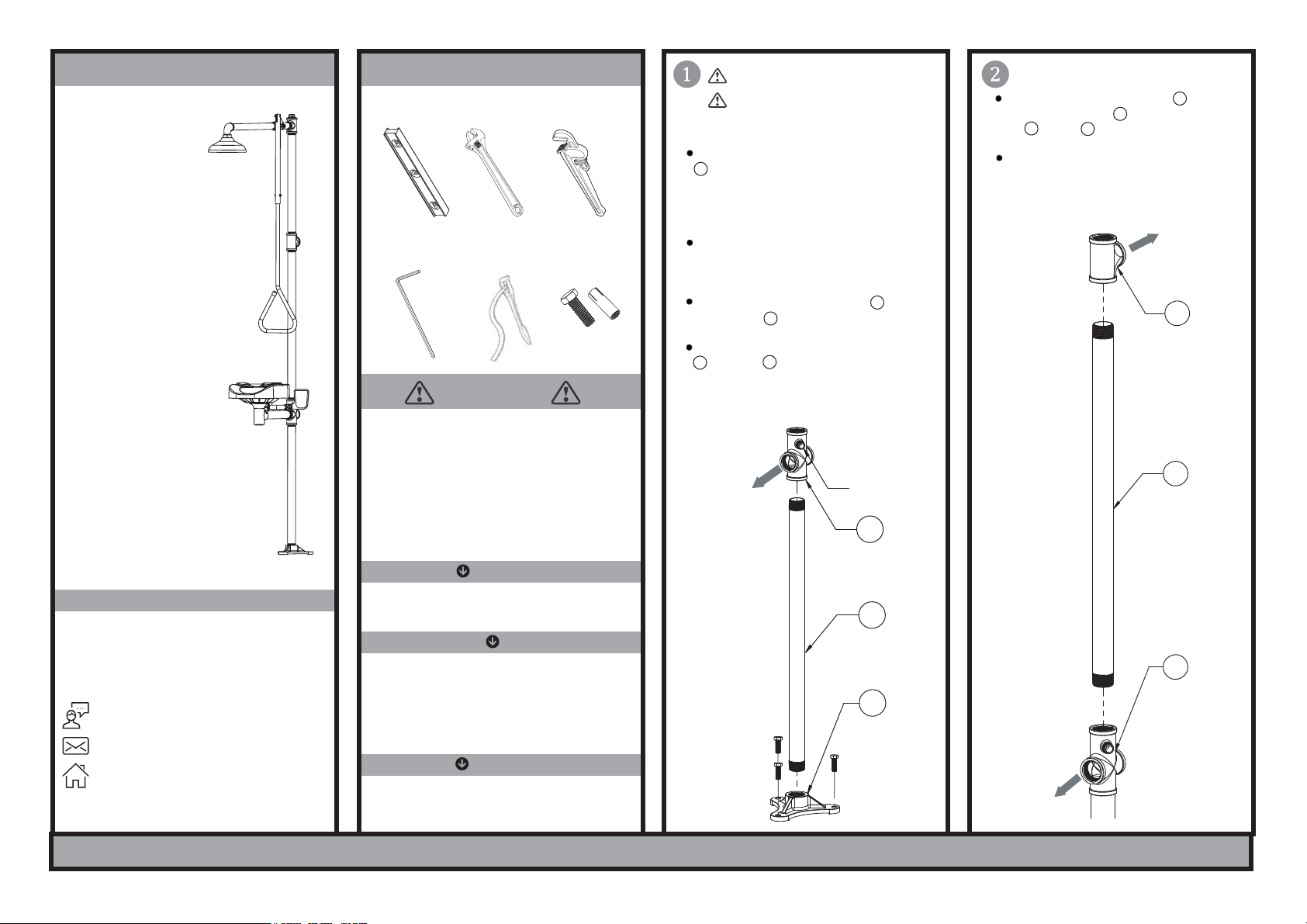
INSTRUCTIONS FOR MODELS
OPTIMUS
™
SE-1200
SE-1250
SE-1255
TOOLS AND SUPPLIES
Level Adjustable
Wrench
Pipe
Wrench
For Standard installation see Page 1.
Use Thread Locker or Sealant on ALL
threaded connections
At desired location, mount Floor Flange
13
on a flat, level surface using suitable
anchors, making sure that one of the three
ears on the Floor Flange is positioned at
what will be the front of the Stanchion.
Assemble 1-1/4” x 32-3/8” Pipe to
Drain/Supply Cross . Assemble
10
Tee to Pipe .
Assure the Side Outlet portion of the Tee
is facing the rear of the Unit.
12
29
29
1-1/4”
ADA INSTALLATION
(FOR STANDARD INSTALLATION SEE PAGE 6)
NEED HELP?
For additional assistance or service please contact:
SPEAKMAN
400 Anchor Mill Road
New Castle, DE 19720
800-537-2107
www.speakmancompany.com
®
Company
92-SE-1200-1255-R2
7/16” Hex Key
Wrench
Strap
Wrench
Mounting
Hardware
(not included)
IMPORTANT
ANSI Z358.1 requires that all safety emergency
equipment shall be activated on a weekly basis to flush
the line and verify proper operation. SPEAKMAN
furnishes a testing record tag (91-0635) with each unit.
On this tag, the date of inspection and the inspector’s
initials should be noted. ANSI Z358.1 specifies that the
height of the spray heads is to be between 33” - 45”
from the floor. Use Thread Locker or Sealant on all
threaded connections. Be sure the Unit is level and
plum.
SAFETY TIPS
Cover your drain to prevent loss of parts. Always wear
eye protection.
MAINTENANCE
Should you need parts to repair this unit, please
reference the parts listing for correct repair part
number. Before any maintenance is done, be sure to
shut the water supply off. Use only genuine
SPEAKMAN parts when repairing or replacing
components. To order parts, call 1-800-537-2107.
WARRANTY
3 year limited warranty.
Additional warranty information can be found at:
www.speakmancompany.com
The Unit should be placed so that there is
sufficient unobstructed area around the
Stanchion.
Assemble
Floor Flange .
Thread
12
onto Pipe . Side Outlets should face
the front and back of the Unit, and the
1/2” male threaded outlet upward at 45°
to the right side of the Unit.
Front of Unit
1-1/4” x 26-7/16” Pipe to
13
1-1/4” x 1/2” Drain/Supply Cross
11
11
1/2” Male
Threading
12
11
13
Rear of Unit
10
29
12
Front of Unit
ADA INSTALLATION - FOR STANDARD INSTALLATION SEE PAGE 1 PG.6
Page 7
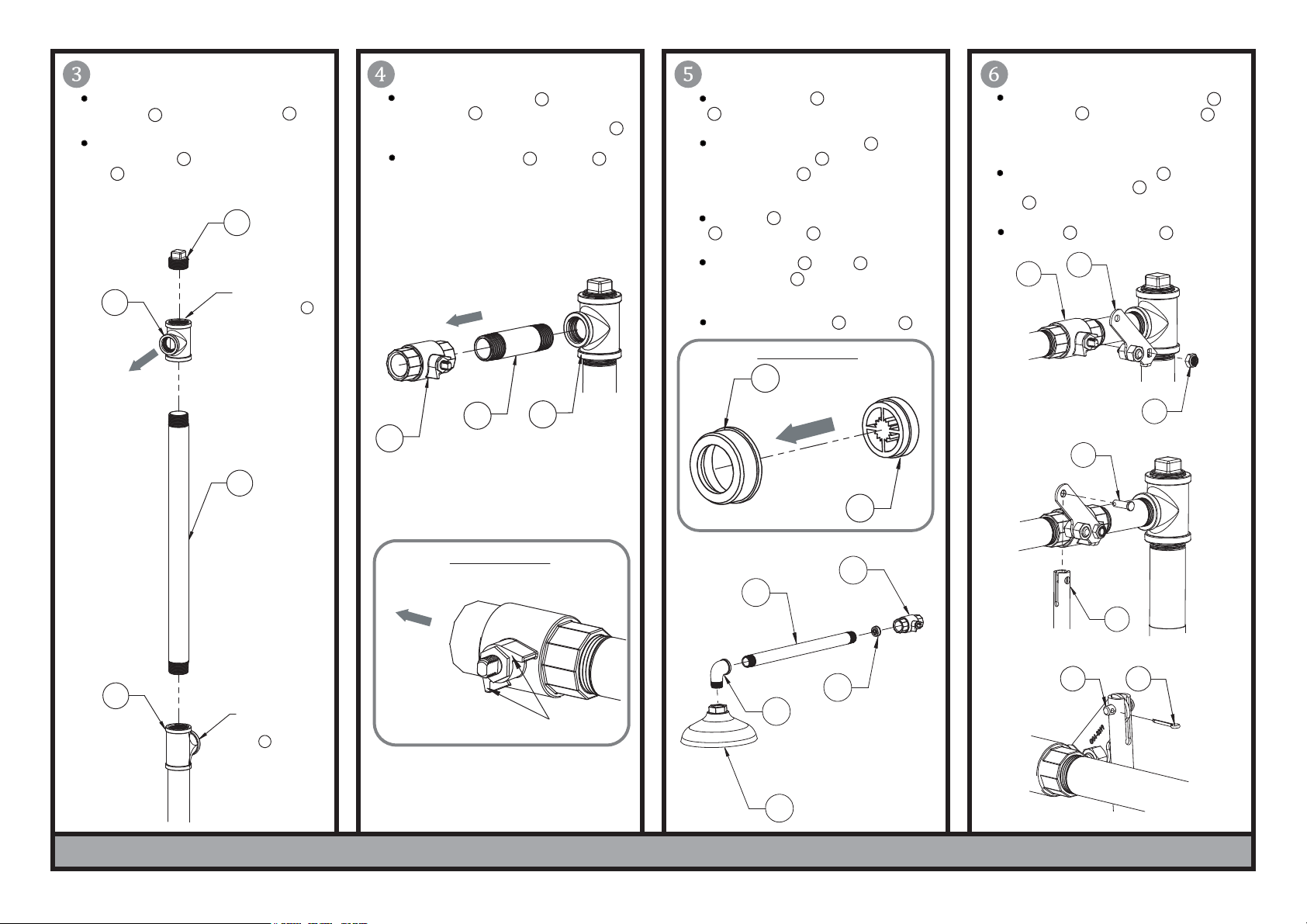
If water supply is coming from above Unit,
install Plug into side outlet of Tee .
7
10
If water supply is coming from behind
Unit, install Plug into top outlet of
8
Tee .
7
7
Assemble 1” x 4-1/2” Pipe into Side
Outlet of Tee . Review View 4a below to
8
understand the orientation of Ball Valve .
Assemble
1” Ball Valve onto Pipe .
6
5
5
6
Valve Stops must be aligned correctly in
order for the Pull Handle to operate
properly.
Insert Flow Control into Floet Housing
3
, referring to Detail View 5a.
Insert Flow Control Assembly into end
1” x 17-5/8” Pipe , so that the flange
of
of Floet Housing is fully seated in the
4
A
2
3
end of Pipe.
Install Pipe with Flow Control Assembly
A
into Ball Valve .
2
5
Assemble the Lever Handle Assembly
to Ball Valve using Nylo-Hex Nut ,
5
16
17
being sure to orient the Handle as shown
below.
Insert the slot in the Pull Rod over the
Lever Handle Assembly and insert
18
Pin .
Secure Pin with Cotter Pin .
18
20
16
19
8
Front of Unit
10
For Back Supply,
install Plug
7
here.
9
For Top Supply,
install Plug
7
here.
To Showerhead
5
To Showerhead
6
Detail View 4a
Valve Stops
Assemble Elbow to Pipe being sure
to orient Elbow so that the outlet is
1
1
2
16
5
facing down.
Assemble Showerhead to Elbow .
14
1
Detail View 5a
3
8
18
4
5
2
A
18
1
17
20
19
14
ADA INSTALLATION - FOR STANDARD INSTALLATION SEE PAGE 1 PG.7
Page 8
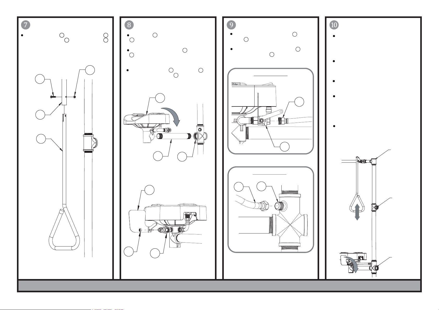
Assemble Pull Rod to Pull Rod Extension
using Machine Screw and Nylo-Hex Nut .
20
27 28
26
28
27
Thread Pipe into Drain/Supply Cross
12
.
Thread entire Bowl Assembly to Pipe
21
, being sure Bowl is level, plumb, and
21
22
horizontal when completely secured.
Install Paddle Handle to Ball Valve
using Nylo-Hex Nut Nut .
24
25
23
Assemble male end of Flex Hose to Ball
23
Valve (Detail View 8a).
Assemble female end of Flex Hose to
Drain/Supply Cross (Detail View 8b).
12
15
15
Detail View 8a
Connect an uninterruptible potable water
supply with a minimum of 30psi flowing
pressure to Water Inlet. Failure to use
potable water can result in further injury.
Connect an adequate drain to Drain
Outlet that complies with all local
plumbing codes.
Turn on water supply and check
connections for leaks.
26
20
24
21
22
12
15
23
Detail View 8b
12
15
To test the Eye/Face Wash, and for
subsequent operation, push the Paddle
Handle forward 90°. The unit will operate
until the Paddle Handle is manually pulled
back to the OFF position.
To test the Shower, and for subsequent
operation, pull the Pull Rod down. The
unit will operate until the Pull Rod is
manually pushed back to the OFF position.
Alternate
Water
Inlet
Standard
Water
Inlet
25
23
Drain
Outlet
ADA INSTALLATION - FOR STANDARD INSTALLATION SEE PAGE 1 PG.8
Page 9
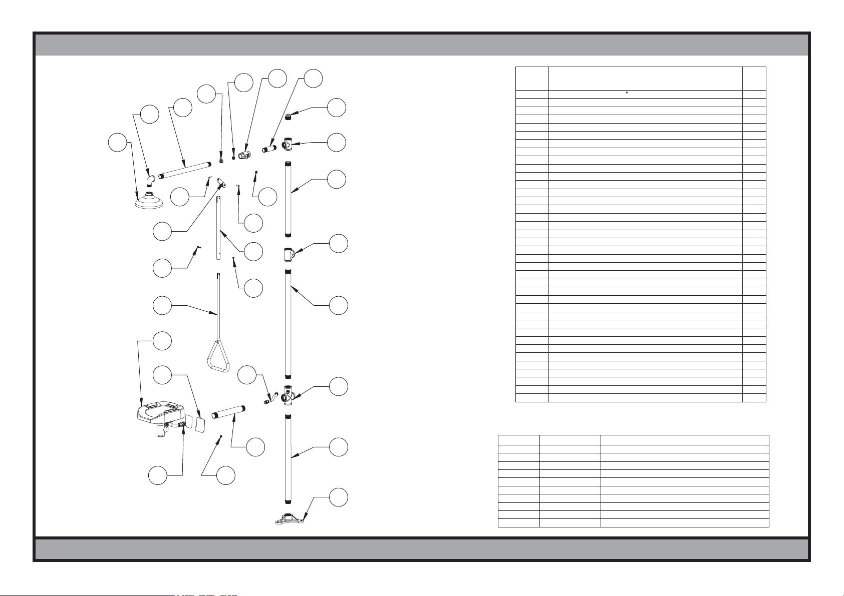
ADA INSTALLATION EXPLODED VIEW / REPAIR PART GROUPS
14
4
5
6
3
1
2
7
8
9
19
17
18
16
10
26
27
28
20
29
22
24
15
12
Item
No.
1
2
3
4
5.1
5.2
6
7
8
9
10
11
12
13
14
15
16.1
16.2
17
18
19
20.1
20.2
21
22
22.1
22.2
22.3
23
23.1
23.2
24
25
26.1*
26.2*
27*
28*
29
*ADA Installation only
Lever Handle w/Spring Plunger (SE-1200/SE-1250)
7/16-20 UNF Stainless Steel Nylo-Hex Nut
Plastic Bowl, Chrome Plated Brass Ball Valve (SE-1
1/2" Chrome Plated Brass Ball Valve (SE-1200/1250)
Aluminum Pull Rod Extension (SE-1200/SE-1250 ADA Only)
Stainless Steel Pull Rod Extension (SE-1255 ADA only)
1" Chrome Plated Brass Ball Valve
1-1/4" x 26-7/16" Galv. Pipe, TBE
1-1/4" x 1/2" Galv. Drain/Supply Cross
Stainless Steel Flexible Supply Hose
Lever Handle w/Spring Plunger (SE-1255)
S/S Bowl, Chrome Plated Brass Ball Valve
S/S Bowl, Stainless Steel Ball Valve
1/2" Stainless Steel Ball Valve (SE-1255)
3/8" Stainless Steel Nylo-Hex Nut
1-1/2" Long 1/4-20 Machine Screw
1/4-20 Stainless Steel Nylo-Hex Nut
Description
1" x 90
Galv. Street Elbow
1" x 19-3/8" Galv. Pipe, TBE
Rubber Floet Housing
20 GPM Flow Control
1" Stainless Steel Ball Valve
1" 4-1/2" Galv. Pipe, TBE
1-1/4" Galv. Plug
1-1/4" x 1-1/4" x 1" Galv. Tee
1-1/4" x 22-1/4" Galv. Pipe, TBE
1-1/4" Galv. Tee
1-1/4" Galv. Floor Flange
8" Deluge Showerhead
Clevis Pin
Cotter Pin
29" Aluminum Pull Rod
29" Stainless Steel Pull Rod
1-1/4" x 11-5/8" Galv. Pipe, TBE
Eyewash Unit
1/2" Ball Valve
Paddle Handle
1-1/4" x 32-3/8" Galv. Pipe, TBE
Qty.
1
1
1
1
1
1
1
1
1
1
1
1
1
1
1
1
1
1
1
1
1
1
1
1
1
1
1
1
1
1
1
1
1
1
1
1
1
23 25
REPAIR PARTS
21
11
13
Item No.
5
5
14
14
20.1 RPG47-0046
20.2 RPG47-0044
22.1
22.2
22.3
15
Part No.
SE-911
SE-911-SS
SE-870
SE-880
SE-1000
SE-1050
SE-1055
RPG63-0094
Description
1" Stainless Steel Ball Valve SE-1255 Only
Aluminum Pull Rod (With ADA Extension)
S/S Pull Rod (With ADA Extension)
PlasticBowl, Chrome Plated Brass Ball Valve
S/S Bowl, Chrome Plated Brass Ball Valve
S/S Bowl, Stainless Steel Ball Valve (SE-1255 only)
1" Ball Valve
8'' Plastic Showerhead
8'' Stainless Steel Showerhead
Stainless Steel Supply Hose
ADA INSTALLATION - FOR STANDARD INSTALLATION SEE PAGE 1 PG.9
Page 10
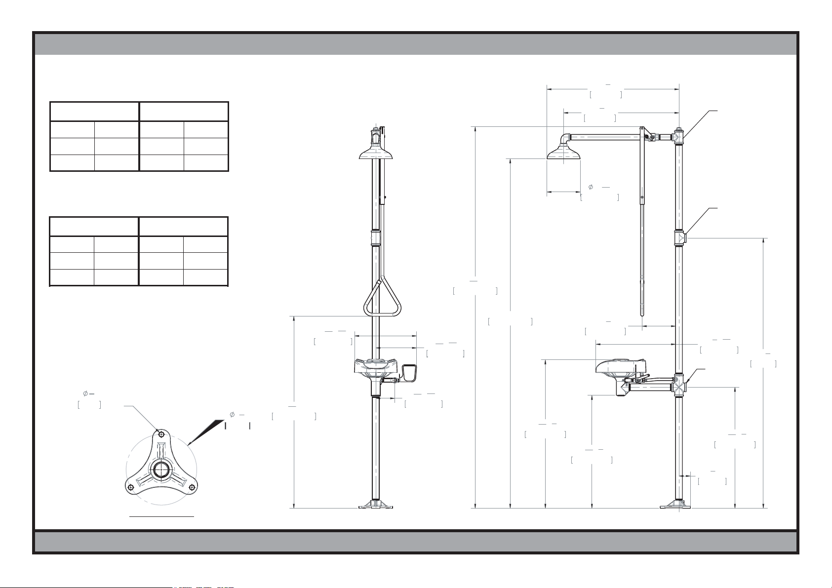
ADA INSTALLATION ROUGH-IN DIMENSIONS
SE-1200/1250/1255
SHOWER FLOW DATA
PRESSURE
psi
30
60
bar
2.07
4.14
FLOW RATE
gpm
20
25
L/min
75
94
SE-1200/1250/1255
EYE/FACEWASH FLOW DATA
PRESSURE
psi
30
60
bar
2.07
4.14
NOTE: ALL UNITS MEET EXISTING ANSI Z358.1 STANDARDS
AND OSHA RULES. PRODUCT IMPROVEMENTS MAY CAUSE
SPECIFICATION AND DIMENSIONAL CHANGES WITHOUT
NOTICE.
1
"
2
13mm
(TYP. 3 PLACES EQUALLY
SPACED 120º APART)
FLOW RATE
gpm
4.9
5.0
L/min
18.5
18.9
7
200mm
7
"
8
3
"±1"
46
16
1172.82mm±25
29
"±
14
32
378.58mm±5
3
"
31
4
806.32mm
3
"
27
4
704.72mm
1
"
8"±
16
203.20mm±2
23
"±1"
32
84"±1"
2133.98mm±25
11
"±
35
16
906.67mm±13
1
"
2
203.53mm±10
5
27
32
689.67mm±10
3
"
8"±
8
3
"±
"
8
91
2329.92mm±25
3
"
16
9
4
16
115.57mm±5
13
9
16
249.10mm±5
3
"±
"
16
3
"±
"
16
1-1/4" NPT (TOP)
FEMALE INLET
1-1/4" NPT
FEMALE INLET
1
"±
19
8
485.91mm±9
1-1/4" NPT
FEMALE OUTLET
738.95mm±10
3
"
2
4
69.85mm
11
"
32
3
"±
29
32
3
"
8
65"±
1651±16
5
"
8
FLOOR FLANGE DETAIL
ADA INSTALLATION - FOR STANDARD INSTALLATION SEE PAGE 1 PG.10
Page 11
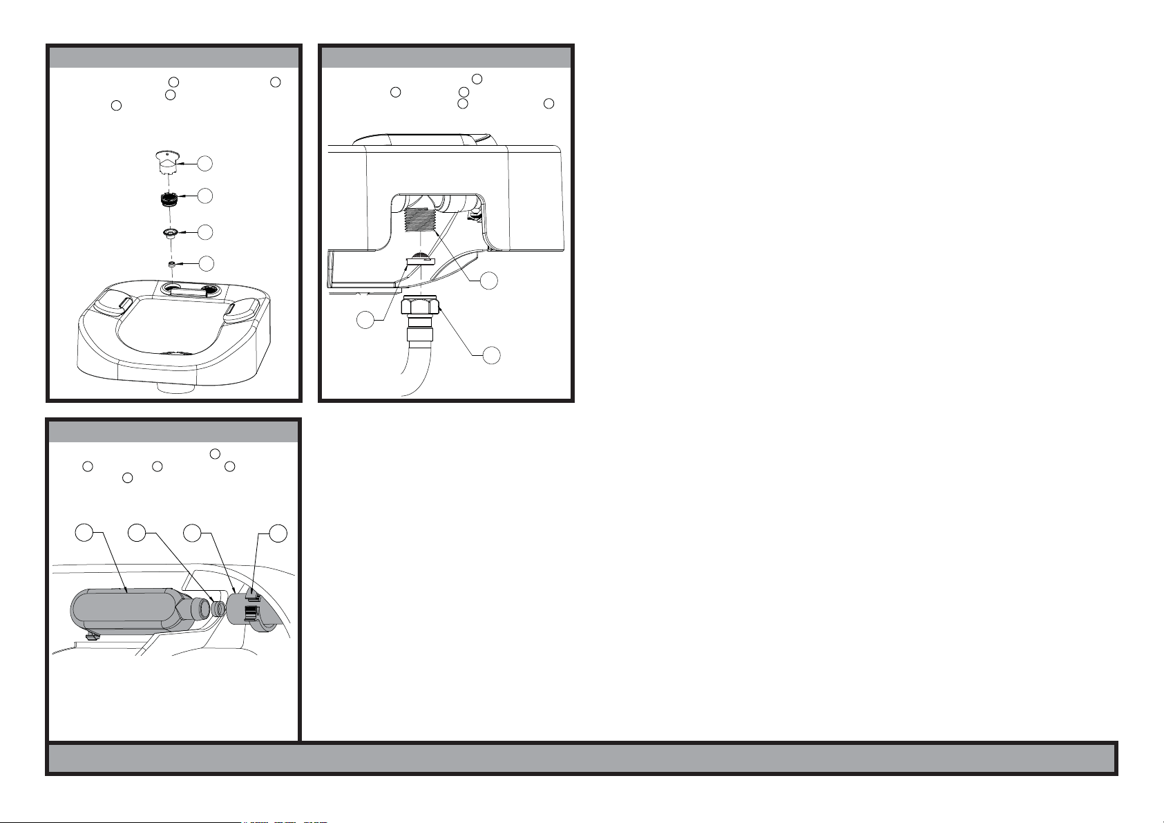
To Clean the Aerated Outlets:
Using the Aerator Wrench , remove the Aerator .
The Flow Control Housing will come out next, with the
Flow Control inside of it. Remove the Flow Control
4
1
3
and check for debris surrounding the o-ring. Flush with
clean water. Check the mesh on the back of the Aerator
for debris. Flush with clean water.
1
2
3
4
2
To Clean the Non-Aerated Outlets:
Begin by removing the Hose Clamp , then remove
2
Hose from Housing . Flow Control can be seen
inside Housing at this point. Remove Flow Control
4
4
and check for debris surrounding the o-ring. Flush with
clean water.
1
3
To Clean the In-Line Strainer:
Begin by removing Supply Hose from Hose
Manifold Tee . The Strainer will be located inside
1
the threading of Supply Hose . Remove Strainer
and check for debris. Flush with clean water.
2
3
2
3
1
3
2
4
3
2
1
CLEANING INSTRUCTIONS PG.11
 Loading...