

Page 1
Instructions for Series:
S-1495
What You Need To Know:
Tools:
Required:
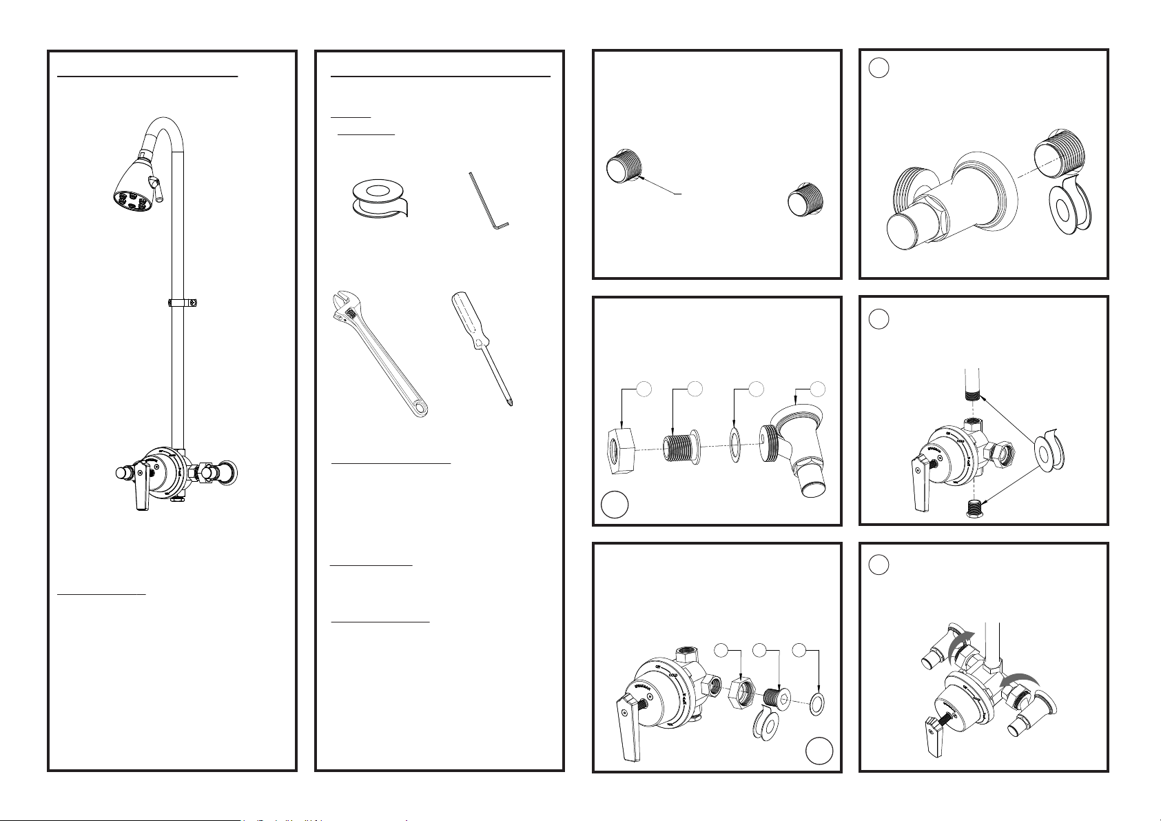
Install the HOT and COLD supply lines for the
①
Valve, either through the wall, from the ceiling,
or from the floor. For ceiling and floor mounts,
hold 1” from finished wall to center of supply
lines. See rough-in diagram on last page.
Retrieve the Union Body. After the application
4
of Thread Seal Tape, thread the Union Body
onto the COLD supply line and tighten with
the Adjustable Wrench. Repeat for HOT supply.
Note:
S-1495-2-AF pictured. Showerhead
will vary between models.
Need Help?
For additional assistance or service call:
SPEAKMAN Company
400 Anchor Mill Road
New Castle, DE 19720
PHONE: 800-537-2107
EMAIL: [email protected]
WEB: www.speakmancompany.com
92-S-1495-R1
*Thread Seal
Tape
*Adjustable
Wrench
*1/2” Allen Wrench
*Phillips Head
Screwdriver
Important Notes:
Be sure to read instructions thoroughly before beginning
installation. Do not overtighten any connections or damage
may occur. Showerhead has a flow control device that
reduces flow to 2.5 GPM / 9.46 L/min maximum to meet
existing ANSI A112.18.1M Standard. Vandal Resistant
standard. Meets ASSE 1016, 1989 Standard.
Safety Tips:
Cover your drain to prevent loss of parts. Always wear eye
protection.
Maintenance:
The Regency Valve relies on ceramic components, quad-rings,
and o-rings for sealing. There are no seat washers or packings
to repair, which reduces the need for routine maintenance.
The valve contains two easily replaceable modules. They are
the balancing module and the regulating module. After
shutting off the water supplies to the valve, simply remove the
trim and unscrew the valve bonnet. When replacing the
balancing module, make sure that the quad-ring seals are
properly installed within the module and that the module is
installed with the seals directly over the body inlet ports. The
gleaming finish of your SPEAKMAN Regency shower can be
cleaned using mild soap and warm water. Dry immediately
with a soft, clean cloth for best results.
1/2” NPT Connection
Disassemble the two Unions. Start by loosening
②
the Union Nut (1). The Union Adapter (2) and
Union Washer (3) usually stay affixed to the
Union Nut. Place the Union Body (4) to the side.
1
2
3
4
Apply Thread Seal Tape to both ends of Shower
5
Arm Gooseneck, and Bottom Plug. Thread
Shower Arm Gooseneck into Valve Body being
sure to properly align outlet. Install Plug into
bottom port of Valve Body and wrench tighten.
2x
If the components in Step 2 did not stay
③
together, insert the Union Adapter (2) into the
Union Nut (1), followed by the Union Washer(3).
After applying Thread Seal Tape to the Union
Adapter, thread the assembly into the COLD
Inlet. Tighten with a 1/2” Allen Wrench. Repeat
for HOT
Inlet.
2
1
3
Insert the Valve Assembly between the installed
6
Union Bodies. Thread Union Nuts onto Valve
Body and wrench tighten, being sure Shower
Arm Gooseneck is in a true vertical position.
Turn on water supply and check for leaks.
2x
Page 2
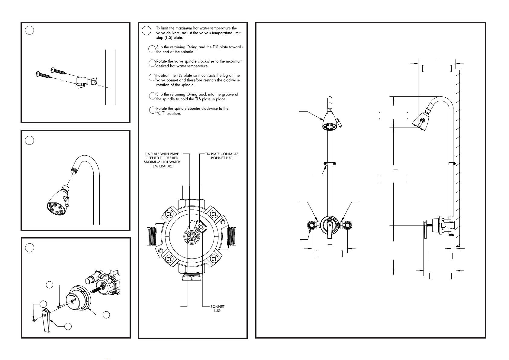
Install Wall Bracket using Supplied Screws.
2
1
3
4
7
Mounting location is optional. In drywall or tile
applications, be sure to use appropriate
hardware.
10
ROUGH-IN DIAGRAM
1
"
1
2
3
4
7
184.29mm
4
Retrieve the Showerhead. Thread onto the
8
Gooseneck and wrench tighten.
Note: Showerhead may differ from illustration.
The Handle and Dial Cap must be removed to
9
adjust the Temperature Limit Stop. Remove the
Handle Screw (1), then slide the Handle (2) off.
Remove the Dial Cap Screw (3) followed by
sliding off the Dial Cap.
6"
7
"
8
1"
25.4mm
5"
127mm
Cold Inlet
Union
152.24mm
18
479.59mm
4'-6"
(1.37 meters)
To Floor
5
S-2252
Pipe Strap
W/ Screws
(Location
Optional)
Hot Inlet
Union
Loose Key
Angle Stop
(2 Places)
7
190.5mm
1
"
2
Notes:
O-RING
1. Dimensions shown are for S-2252 Showerhead.
2. Dimensions are subject to change without notice.
3. Unit can be also be installed in a ceiling or floor supply.
 Loading...