

Page 1

®
SPEAKMAN
S-1590
Installation, Maintenance & Operation Instructions
SENTINEL MARK II® ROYALE™ SHOWERPAC®
DESCRIPTION
Speakman Sentinel Mark II® Royale™ SHOWERPAC® exposed anti-scald balanced pressure SHOWERPAC®.
• 18 gauge stainless steel outer shielding.
• Stainless steel self-draining soap dish.
• Chrome plated brass lever handle.
• Adjustable temperature limit stop.
• Brass valve body.
• Integral spring check stops.
• ROYALE™ Pressure balancing module.
• Concealed integral mounting lugs.
S-2292 showerhead with flow control device reduces flow to 2.5 GPM/9.46 L/min maximum to meet existing
ANSI A112.18.1M Standard. Standard ½” copper tube inlets through the wall or dropped from the ceiling.
Vandal resistant construction. Meets ASSE 1016.
SpecificAtions
SUPPLY: ½” COPPER TUBE INLETS
FLOW RATE: SHOWERHEAD, 2.5 GPM/9.46 L/min MAX
Options:
LH
VPC-2
Less Showerhead
Stainless steel vertical pipe
cover, 2 ft. (610mm) sections.
(Must order as separate item.)
2 – S-2252
3 – S-2253
INSTALLATION
Note: Refer to the complete installation/rough-in literature supplied with the valve.
1. Remove the complete unit from the box. Remove the shield assembly from the valve unit
by removing the screw above the showerhead elbow and the screw near the dial cap.
Save the two (2) screws.
2. Determine the horizontal positioning of the valve unit. Determine the floor to showerhead heights
from the Recommended Head Heights chart.
3. Holding the unit against the finished wall in the proper position, mark the location of the top mounting
bracket holes (2), and the bottom mounting bracket hole (1). Remove unit from the wall and install
any mounting anchors (not provided), as detailed by the individual room specifications.
4. Position the unit against the wall, secure top mounting bracket screws (2) (not provided). Secure
bottom mounting bracket screw (1) (not provided). Be sure to select hardware appropriate for
the material you are mounting to. (I.E. wood screws, anchors, etc.)
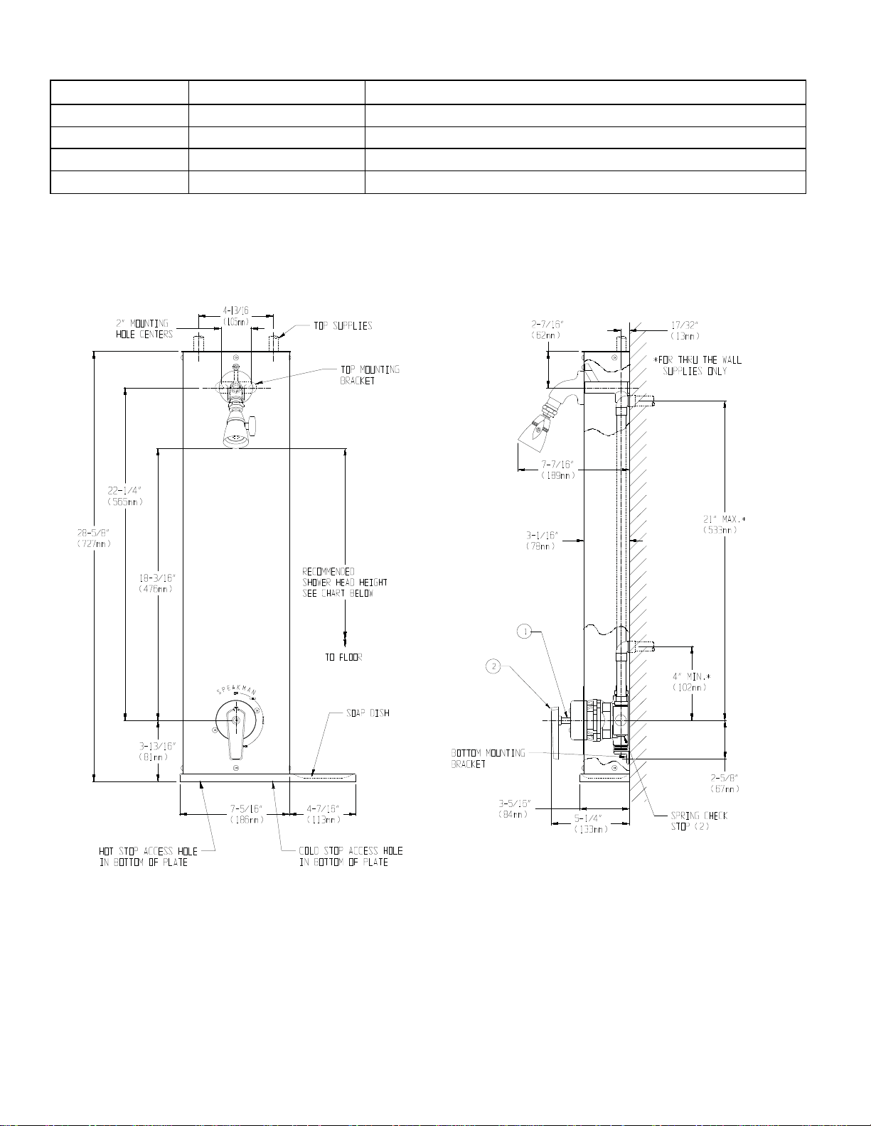
5. Connect the supply lines to the inlets of the units. Supply lines must be on 4-13/16” centers. If unit
has top supply lines they must also be 17/32” from center of lines to finished wall. Do not secure top
supply lines to wall until complete Showerpac® unit with shielding has been installed. Place handle on
valve spindle and rotate counter-clockwise. Remove handle, turn both supplies on and check supply
line connections for leaks.
6. Attach bottom/soap dish plate to shield with three (3) 3/8” long screws provided. Make sure back
edge of plate is flush with side edges of shield. Tighten screws with 1/8” Allen wrench (provided).
Attach top cover plate to shield same as above on unit without a vertical pipe cover (VPC-2).
Unit with a VPC-2 does not use the top cover plate.
ANYSTREAM® Shower head
ANYSTREAM® Shower head
SPEAKMAN®
400 Anchor Mill Rd. New Castle, DE 19720 Phone: 800-537-2107 Fax: 800-977-2747
09/01/15 www.speakman.com 92-S-1590-R2
Page 2

7. Attach shield assembly to valving unit by positioning shower head elbow of shield with top flange
O-ring and lower large hole of shield with dial cap of unit. Slide shield into place against finish wall.
Secure shield to unit with (3) screws provided. Use the 3/8” long screw for the top mounting hole
above the showerhead elbow and the two (2) 1-1/4” long screws for the lower mounting holes near
the dial cap. Tighten screws with Allen wrench provided.
8. Apply pipe thread sealant or tape to shower head elbow threads of shield. Attach shower head
to elbow. Wrench tighten. Properly position handle in the “OFF” position and secure with ½” long
screw provided.
9. With spring check stops fully opened, turn handle to the warm position and check shower head
connection for leaks. Turn valve off.
10. To adjust the temperature limit stop, remove the handle and dial cap from the valve. Remove the
rubber retaining ring and the first temperature limit stop (TLS) plate. The second TLS plate should
be adjusted so that it comes into contact with the lower side of the bonnet post when the valve is in
the “OFF” position. Now turn the valve on to the desired maximum hot water discharge temperature,
assemble the first TLS plate so that it contacts the upper side of the bonnet post. Turn valve off and
reassemble the retaining ring, cap and handle. Because of fluctuations in the hot and cold water
temperatures, it is not recommended that the temperature limit stop be used to preset the unit for
showering temperatures.
11. Back to Back Installation: On this type of installation the regulating disc must be rotated 180° on the
valve on which the hot and cold inlets were reversed. Refer to the complete installation/rough-in
literature supplied with the valve and see “Maintenance” for additional instructions.
OPERATION
Note: Both the hot and cold water must be on for the valve to operate properly. The handle of the valve
is rotated clockwise to the desired temperature and then counter clockwise to turn the valve off.
MAINTENANCE
The ROYALE™ valve relies on plastic and rubber components, quad-rings and O-rings for sealing. There are
no seat washers or packings to repair, which reduces the need for routine maintenance. The valve contains
a plastic regulating disc with rubber seal and a balancing module. After shutting off the integral stops
through the access holes in the bottom/soap dish plate simply remove the valve handle and the shield
assembly (total of four (4) screws) from the unit. Unscrew four (4) bonnet screws and remove bonnet
assembly. When replacing the balance module, make sure that the quad-ring seals are properly installed
within the module and that the module is installed with the seals directly over the body inlet ports. When
replacing the regulating disc refer to the complete installation/rough-in literature supplied with the valve.
It is suggested that the Temperature Limit Stop (TLS) be seasonally adjusted because of variations in
the cold supply temperature to ensure the safety and comfort of the users.
Note: When servicing these modules and adjusting the TLS refer to the installation sheet supplied with
the valve.
RECOMMENDED HEAD HEIGHTS
MEN 6’0”
BOYS, SENIOR HIGH 5’10”
BOYS, JUNIOR HIGH 5’6”
BOYS, ELEMENTARY
WOMEN 5’8”
GIRLS, SENIOR HIGH 5’6”
GIRLS, JUNIOR HIGH 5’4”
GIRLS, ELEMENTARY 5’2”
5’4”
SPEAKMAN®
400 Anchor Mill Rd. New Castle, DE 19720 Phone: 800-537-2107 Fax: 800-977-2747
09/01/15 www.speakman.com 92-S-1590-R2
Page 3
REPAIR/REPLACEMENT PARTS (SEE ROUGH-IN)
ITEM NUMBER PART NUMBER DESCRIPTION
1 RPG03-0371 SPINDLE ASSEMBLY W/ O-RINGS & WASHERS
NOT SHOWN G05-0412-MO CERAMIC REGULATING MODULE ASSEMBLY W/ O-RINGS
NOT SHOWN G05-0413 BALANCING MODULE ASSEMBLY W/ QUAD RINGS
2 RPG04-0367-PC
HANDLE WITH SCREW
ROUGH-IN DIMENSIONS
NOTES:
1. ALL DIMENSIONS ARE IN INCHES (MILLIMETERS) AND SUBJECT TO CHANGE WITHOUT NOTICE.
2. UNIT CAN BE INSTALLED WITH TOP OR THROUGH THE WALL SUPPLIES.
3. ½” COPPER TUBE INLETS. SUPPLY PIPING NOT INCLUDED.
SPEAKMAN®
400 Anchor Mill Rd. New Castle, DE 19720 Phone: 800-537-2107 Fax: 800-977-2747
09/01/15 www.speakman.com 92-S-1590-R2
 Loading...