

Page 1
SPEAKMAN COMPANY
SM- Regency/Royale Valve, Showerhead, Tub Spout, & Combo Series
Installation, Maintenance & Operation Instructions
DESCRIPTION
Speakman Sentinel Mark II Regency/Royale concealed anti-scald balanced pressure shower /bath valve & combinations. Chrome
plated brass wall plate (Regency). Chrome plated plastic wall plate (Royale). Chrome plated brass lever handle. Adjustable
temperature limit stop. Brass body. Noryl® bonnet. Pressure balancing module. Ceramic temperature regulating module. Can be
installed back to back. Roughing-in template. S-2270-AF COSMOPOLITAN® showerhead (If applicable), S-2280-AF
Anystream wall mounted showerhead (If applicable), or VS-100 Handheld Shower (If applicable) with flow control device
reduces flow to 2.5 GPM/9.46 LPM maximum to meet existing ASME A112.18.1/CSA B125.1 Standard. Chrome plate brass
shower arm and wall flange (If applicable). Chrome plated tub spout (If applicable). Four port valve with ½” NPT female inlets
and outlets. Meets ASSE 1016 Standard.
SPECIFICATIONS
SUPPLY: ½” NPT FEMALE (VALVE)
FLOW RATE: 2.5 GPM/9.46 LPM MAX. (SHOWERHEAD AND/OR HANDHELD SHOWER, IF APPLICABLE)
SHIPPING WEIGHT: 3.5 LBS (SM-3000)
OPTIONS
◊ 1 - S-2251 Showerhead ◊ 4 - S-2220-AF Showerhead ◊ AP - Anchor Plate (S-2280-AF
Showerhead Only)
◊ 2 - S-2252-AF Showerhead ◊ 6 - S-2288-AF Showerhead ◊ BJ - Ball Joint (S-2280-AF
Showerhead Only)
◊ 2VR - S-2252-AF Vandal
Resistant Showerhead
◊ PC –
Polish Chrome Handheld
Shower (Combo w/VS-100 Only)
◊ VH-
White Vinyl Hose (Combo
w/Handheld Shower Only)
◊ 3 - S-2253-AF Showerhead ◊ 9 - S-2292-AF Showerhead ◊ LH - Less Showerhead
◊ 7 - S-2291-AF Showerhead ◊ SCS - Spring Check Stops ◊
INSTALLATION INSTRUCTIONS
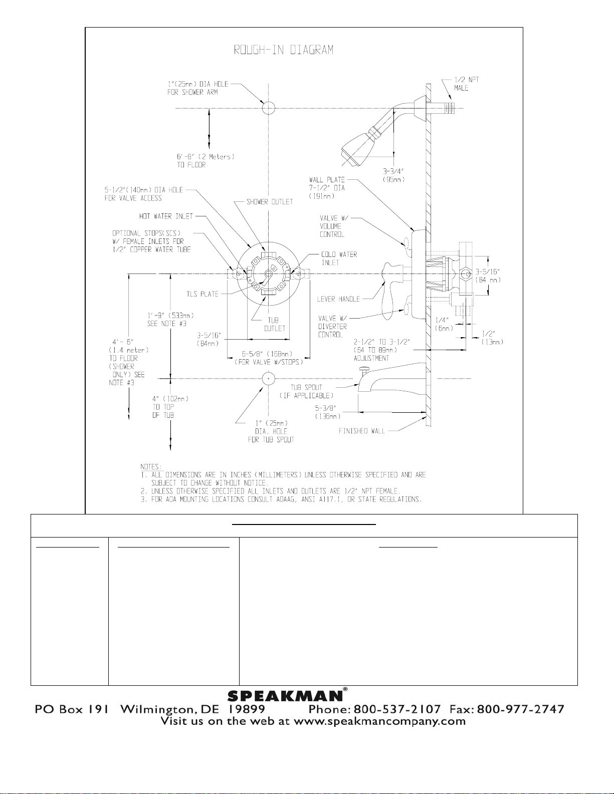
Important- Read these instructions before installing the valve. Use the correct “Rough-in Diagram” for the unit that is being
installed. Maximum water pressure: 125 PSI static; minimum water pressure: 20 PSI flowing; maximum supply temperature: 160° F;
minimum supply temperature: 40° F. Use a suitable sealant on all threaded connections and when soldering, remove all internal parts
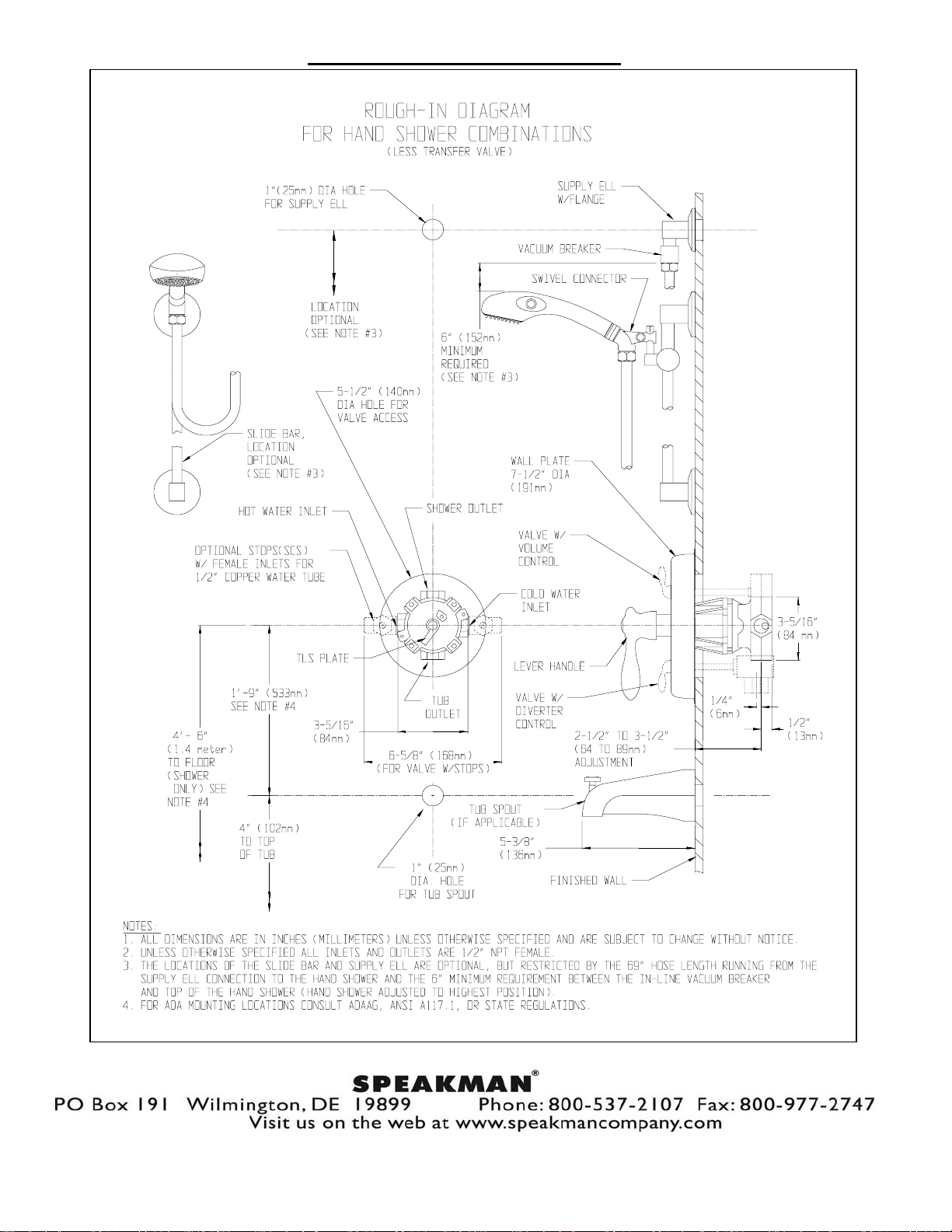
prior to applying heat to the optional (SCS) stop bodies. The valve rough-in adjustments are 2-1/2” to 3-1/2” from the finished wall
to the centerline of the hot & cold inlets of the valve body. On diverter model valves, do not
the tub spout. The diverter mechanism in the valve is so designed that it cannot be subject to any back pressure, other than imposed
by a standard tub spout (1/2 copper or ½ NPT minimum spout inlet).
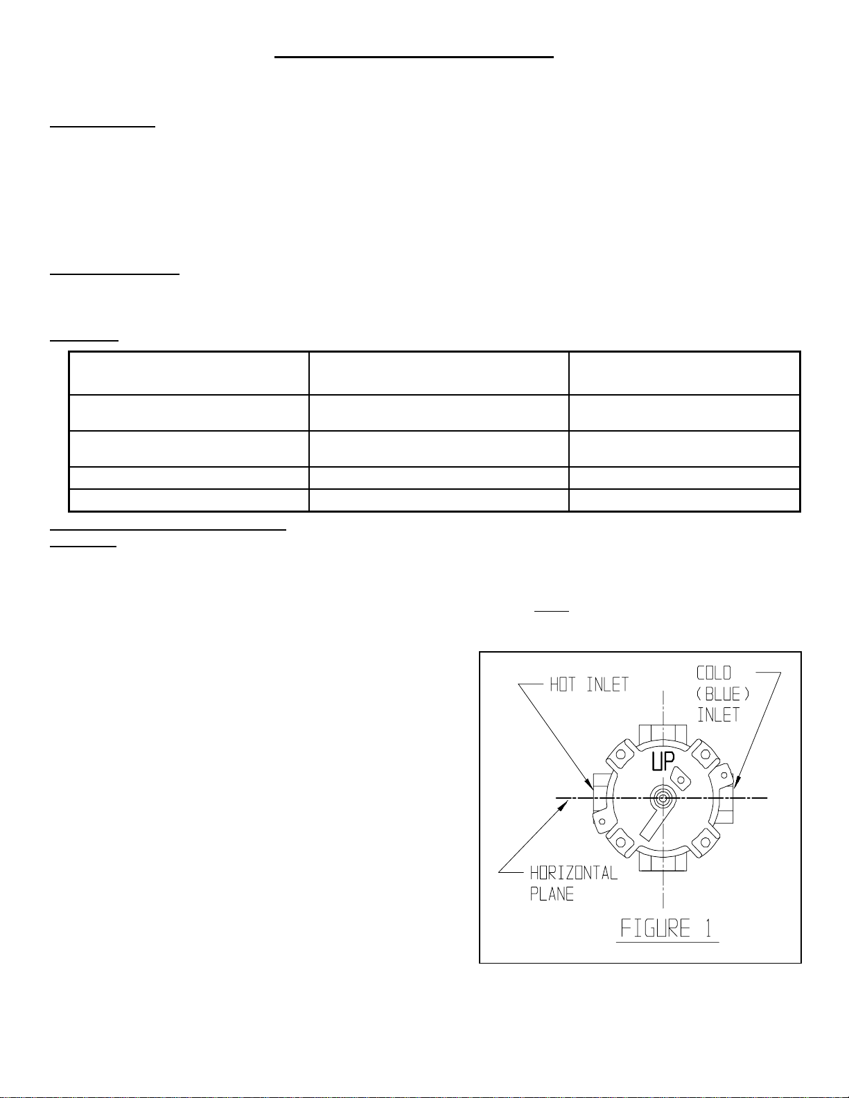
1) Referring to the correct “Rough-in Diagram” for the unit that is being
installed (See the back page or the separate insert sheet), install the hot
& cold supply lines for the valve, making sure they are on an accurate
horizontal plane. Taking the valve assembly, making sure the “UP” on
the valve bonnet is in the up position, connect the hot supply line to the
left side of the valve & the cold supply line to the right (marked
“BLUE”) side of the valve. Make sure the valve is straight, level, &
positioned properly in the wall (See Figure 1). See Page 2 for “Back To
Back” valve installation instructions.
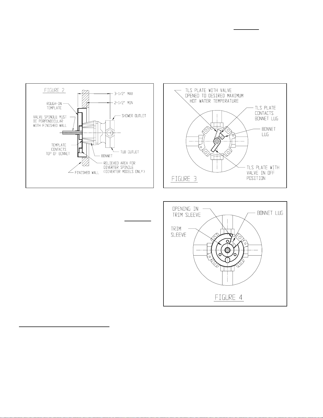
2) Slip the rough-in template over the valve control spindle. If the
opening in the wall is smaller then the outside diameter of the template,
trace the outside diameter of the template, remove the template, and
recut the opening in the wall. Slip the template onto the valve again
until the template bottoms out on the top of the valve bonnet (See
Figure 2). Note- When installing a valve with the built-in diverter,
make sure the template is positioned so the plastic diverter spindle is in
the relieved area of the template. The finished wall should fall between
the minimum and maximum limits of the template if the valve has been
installed properly. Leave the template in place if the finished wall has
to be installed. The template will insure the proper size opening for
repair accessibility, as well as protect the valve from damage during the
finished wall installation.
substitute other outlet accessories for
PAGE 1 03/07
92-2803 R-2
Page 2
3) Install the rough piping and transfer valve (If applicable) to the shower and/or tub outlets of the valve. If the installation is
only using one outlet, be sure to plug the other outlet with the provided pipe plug. If applicable, construct the finished wall.
4) With the necessary opening(s) in the finished wall, assemble the accessory(s) to the rough piping (Important-
See separate
“Accessory Installation Instructions” supplied with some of the accessories). With the rough-in template removed & the valve
turned OFF, turn both the hot & cold water supplies ON. Using the handle, operate the valve checking all the connections for
leaks.
5) To limit the maximum hot water temperature the valve delivers, adjust the valve’s temperature limit stop (TLS) plate (See
Figure 3). Slip the retaining o-ring and the TLS plate towards the end of the spindle. Rotate the valve handle clockwise to the
maximum desired hot water temperature. Position the TLS plate so it contacts the lug on the valve bonnet and therefore
restricts the clockwise rotation of the handle. Slip the retaining o-ring back into the groove of the spindle. Turn off the valve
and remove the handle.
Note- For shower/tub valve with built-in diverter, make sure the
plastic diverter spindle is in the “UP” position (spindle is marked
“UP”).
6) Slip the trim sleeve onto the spindle and valve. Important-
Rotate the sleeve so that the lug on the valve bonnet is in the pie
shaped opening of the sleeve (See Figure 4). Apply clear
silicone sealant to the back side outer flat surface of the wall
plate. For valve with a brass wall plate, make sure the threaded
boss in the wall plate is below the center hole. Carefully slip the
wall plate onto the trim sleeve, volume control spindle (If
applicable) or diverter spindle (If applicable), and properly
position against the finished wall. Fasten the wall plate to the
valve using the (2) long wall plate screws. Do not over tighten
the wall plate screws. Wipe off any excess sealant from around
the outer edge of the wall plate. If applicable, remove clear
protective sheet from top of index plate. Slip the index plate
over the trim sleeve and fasten to the wall plate with the screw
& flat washer provided. Properly position the handle onto the
valve spindle and screw into place. Push index button into the
handle.
BACK TO BACK INSTALLATION
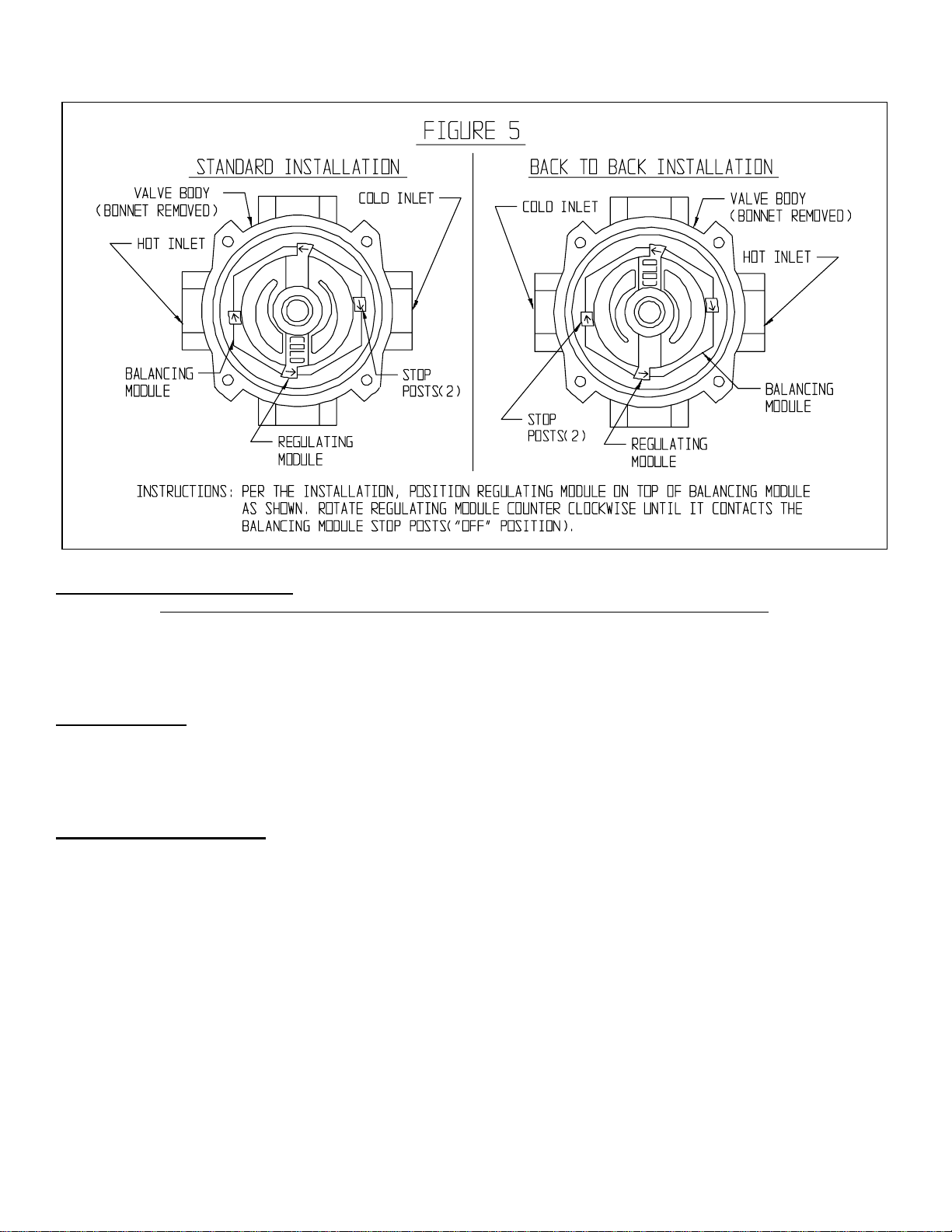
On this type of installation, the regulating module must be rotated 180° on the valve on which the hot & cold inlets are reversed.
Refer to Figure 5 on the next page for the proper positioning of the regulating module.
1) Make sure the hot & cold water supplier are shut OFF. With the valve in the OFF position, remove the (4) valve bonnet
screws. Carefully remove the bonnet, making sure the regulating module does not fall out, onto the floor. The regulating
module sits on top of the balancing module, but may come off with the bonnet. If necessary remove the regulating module.
2) Reposition the regulating module per the Figure 5 drawing. Rotate the module counter clockwise until the module stops come
in contact with the balancing module stop posts.
3) Make sure the large bonnet o-ring seal is installed and seated properly in the valve body. Reassemble the valve bonnet, making
sure the “UP” on the bonnet is in the up position. Tighten the (4) bonnet screws.
PAGE 2 03/07
92-2803 R-2
Page 3
OPERATION INSTRUCTIONS
Important- Both hot and cold water supplies must be FULL on for the valve to operate properly.
Rotate the valve handle clockwise to the desired temperature. To shut the valve OFF, rotate the handle counter clockwise. Volume
control models have an additional lever handle located at the top of the wall plate. Rotation of this handle controls the discharge
volume from the shower outlet of the valve. Diverter models have a similar handle located at the bottom of the wall plate. Rotation
of this handle diverts the discharge flow from the tub spout to the shower outlet or from the shower outlet to the tub spout.
MAINTENANCE
The shower/bath valve is washerless and requires no routine maintenance. The valve uses a ceramic regulating module and a
balancing module. There are no seat washers or packing to repair. For servicing the valve modules, see the instructions below.
The gleaming finish of your SPEAKMAN Regency/Royale valve can be cleaned by using mild soap and warm water. Dry
immediately with a soft, clean cloth for best results.
(CARE and CLEANING)
SERVICE INSTRUCTIONS
1) Shut off the hot & cold water supplies to the valve. Remove handle index button & handle. Remove index screw & index (If
applicable). Remove wall plate screws (2) & wall plate.
2) With the valve in the OFF position, remove the (4) valve bonnet screws. Carefully remove the bonnet, making sure the
regulating module does not fall out, onto the floor. The regulating module sits on top of the balancing module, but may come
off with the bonnet. If necessary remove the regulating module.
3) If necessary remove the balancing module from the valve body. If it does not easily pull out, take a pair of pliers and carefully
grab the module and pull out of body.
4) Replace the necessary parts with new parts. When replacing the balancing module, make sure that the quad-rings (2) are
properly installed in the recesses on the bottom of the module. These quad-rings seal over the hot & cold inlet holes inside the
body. When replacing the regulating module, refer to Figure 5 for proper positioning of module. Rotate the regulating module
counter clockwise until the module stops come in contact with the balancing module stop posts.
5) Make sure the large bonnet o-ring seal is installed and seated properly in the valve body. Reassemble the valve bonnet, making
sure the “UP” on the bonnet is in the up position. Tighten the (4) bonnet screws. Turn ON the hot & cold water supplies. Check
valve for leaks. If necessary, adjust the TLS plate (See Step 5 of the installation instructions).
6) Reassemble the trim parts, reversing the above procedure.
PAGE 3 03/07
92-2803 R-2
Page 4
ITEM NUMBER
1
2
3
4
5
6
7
8
9
10
11
PART OR GROUP NUMBER
RPG49-0126
RPG05-0718
RPG03-0259-RCP
RPG03-0365-RCP
RPG03-0366-RCP
RPG49-0076
G05-0412-MO
G05-0413
RPG49-0127
RPG03-0372
RPG03-0362-MO
REPAIR / REPLACEMENT PARTS
BONNET O-RING
BONNET, SCREWS (4), & O-RING REPAIR GROUP
STANDARD VALVE SPINDLE, WASHERS (2), & O-RINGS (2) REPAIR GROUP
1” LONGER VALVE SPINDLE, WASHERS (2), & O-RINGS (2) REPAIR GROUP
1-1/2” LONGER VALVE SPINDLE, WASHERS (2), & O-RINGS (2) REPAIR GROUP
SPINDLE O-RING REPAIR GROUP (4 O-RINGS PER BAG)
REGULATING MODULE REPAIR GROUP (COMPLETE MODULE)
BALANCING MODULE REPAIR GROUP (COMPLETE MODULE)
QUAD RINGS (2) FOR BALANCING MODULE
VOLUME CONTROL SPINDLE REPAIR GROUP (SPINDLE & O-RING)
DIVERTER SPINDLE REPAIR GROUP (SPINDLE & O-RING)
DESCRIPTION
PAGE 4 03/07
92-2803 R-2
Page 5
SPEAKMAN COMPANY
02/07
92-2804
 Loading...