

Page 1
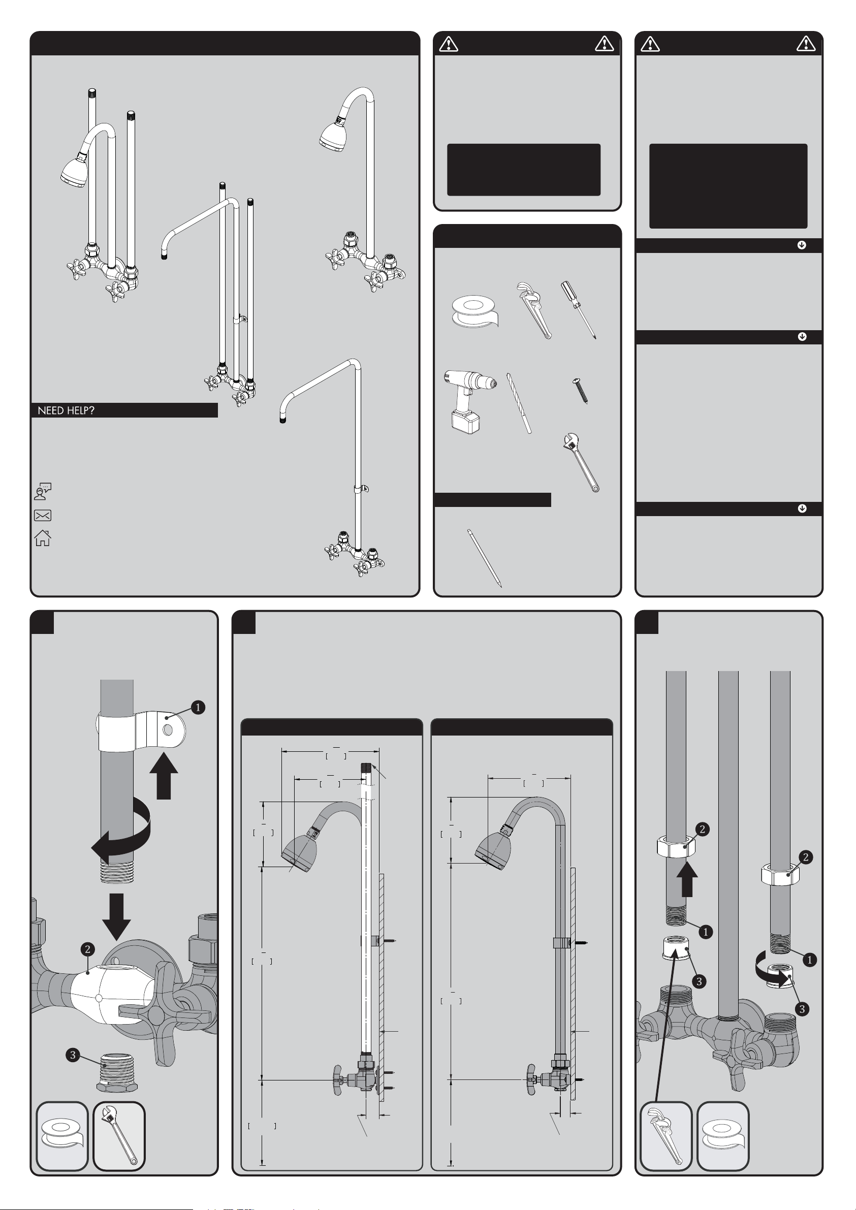
INSTRUCTIONS FOR MODELS
92-SC-12XX-01
For additional assistance or service please contact:
SPEAKMAN
®
Company
400 Anchor Mill Road
New Castle, DE 19720
800-537-2107
www.speakman.com
SC-1210 SERIES SC-1220 SERIES
SC-1230 SERIES
SC-1240 SERIES
HELPFUL TOOLS & SUPPLIES:
Pencil
TOOLS AND SUPPLIES
Thread Seal
Tape
Pipe
Wrench
Drill Drill Bit
3/16”
Mounting Hardware
(Included)
Adjustable
Wrench
Phillips
Screwdriver
Warranty information can be found at:
www.speakman.com
WARRANTY
MAINTENANCE
Cover your drain to prevent loss of parts. Be sure to
wear eye protection while cutting pipe.
SAFETY TIPS
FREEZE PROTECTION
Freeze damage to the shower unit will void the Freeze damage to the shower unit will void the
warranty. It is important to winterize the complete warranty. It is important to winterize the complete
shower unit. The unit must be drained of all water shower unit. The unit must be drained of all water
in freezing conditions. This includes removing the in freezing conditions. This includes removing the
valve cartridge and the shower head from the unit. valve cartridge and the shower head from the unit.
Store the valve cartridge and shower head indoors.Store the valve cartridge and shower head indoors.
• Mounting location must be capable of supporting
the product in use.
IMPORTANT
• Do not over-tighten any connections or damage
1
Slide the Strap (1) onto the Shower Arm. Then
apply sealant to inlet threads of Shower Arm
and the Plug (3). Screw the Shower Arm into the
Valve Body (2). Tighten and position outlet
perpendicular with Valve Body. Use Adjustable
Wrench to tighten the Plug (3) into the Valve
Body (2).
2
Following the rough-in dimensions for your model (located ot the end of this manual), install Supply Pipes at
proper location. See images below for reference.
FITTING WITH WALL FLANGE:
Apply pipe sealant to one end of Supply Pipes
(provided). Screw pipes into supply lines.
NOTE- Supply lines must have 1/2 NPT female
threaded ends and be 1-1/8” from center of
supply line to finished wall.
FITTING WITH LUGS:
Supply lines must have 1/2 NPT male threaded
ends and be 7/8” from center of supply line to
finished wall.
18
1
2
"
470mm
5
1
2
"
143mm
4'-6'
137 Meters
TO FLOOR
8
7
16
"
215mm
6
3
16
"
157mm
SUPPLY LINE
FINISHED
WALL
SURFACE
1¹⁄8”
MOUNTING DEPTH
FITTING WITH WALL FLANGE
4"-6"
[1.37 Meters]
TO FLOOR
18
1
2
"
470mm
5
1
2
"
143mm
7
1
4
"
193mm
FINISHED
WALL
SURFACE
7
⁄8”
MOUNTING DEPTH
FITTING WITH LUGS
3
Apply sealant to threads of Supply Lines (1). Slip
Coupling Nuts (2) onto Supply Lines and screw
Swivels (3) up hand tight. Gripping on small
diameter of Swivels with a Pipe Wrench, tighten
pipes and/or Swivels.
may occur.
• Be sure to read instructions thoroughly before
beginning installation.
• This shower valve has an operating range of
20-80 psi.
NOTE: Shut off water supplies. Supplies
must be on 6” centers. Recommended
height from center of valve body to floor
is 54”. Valve body is reversible to take
supplies from below.
CAUTION: When outdoor temperature
rises above 90 degrees, use caution to
prevent scalding from water stored within
the unit. It is recommended to flush the unit
by turning it on for 30 seconds before
entering the shower water. This will avoid
accidental scalding by the user and ensure
safe use of the shower unit.
The shower valves are washerless and require no routine
maintenance. The gleaming finish of your SPEAKMAN
Commander shower can be cleaned by using mild soap
and warm water. Dry immediately with a soft, clean
cloth for best results. To remove the index button on the
vandal resistant handles, locate knockout hole on handle
underneath one of the arms of the handle. Insert a rigid
pin (1/8” diameter or smaller) into hole and knockout
index button.
Your new Speakman Product is designed for years of
trouble-free performance. Keep it looking new by
cleaning it periodically with a soft cloth. The use of harsh
chemicals and abrasives on any of the Speakman custom
finish products may damage the finish and void the
product warranty. Please be sure to only use approved
cleaners. Please contact Speakman for any clarification
of acceptable cleaners.
Page 2
4
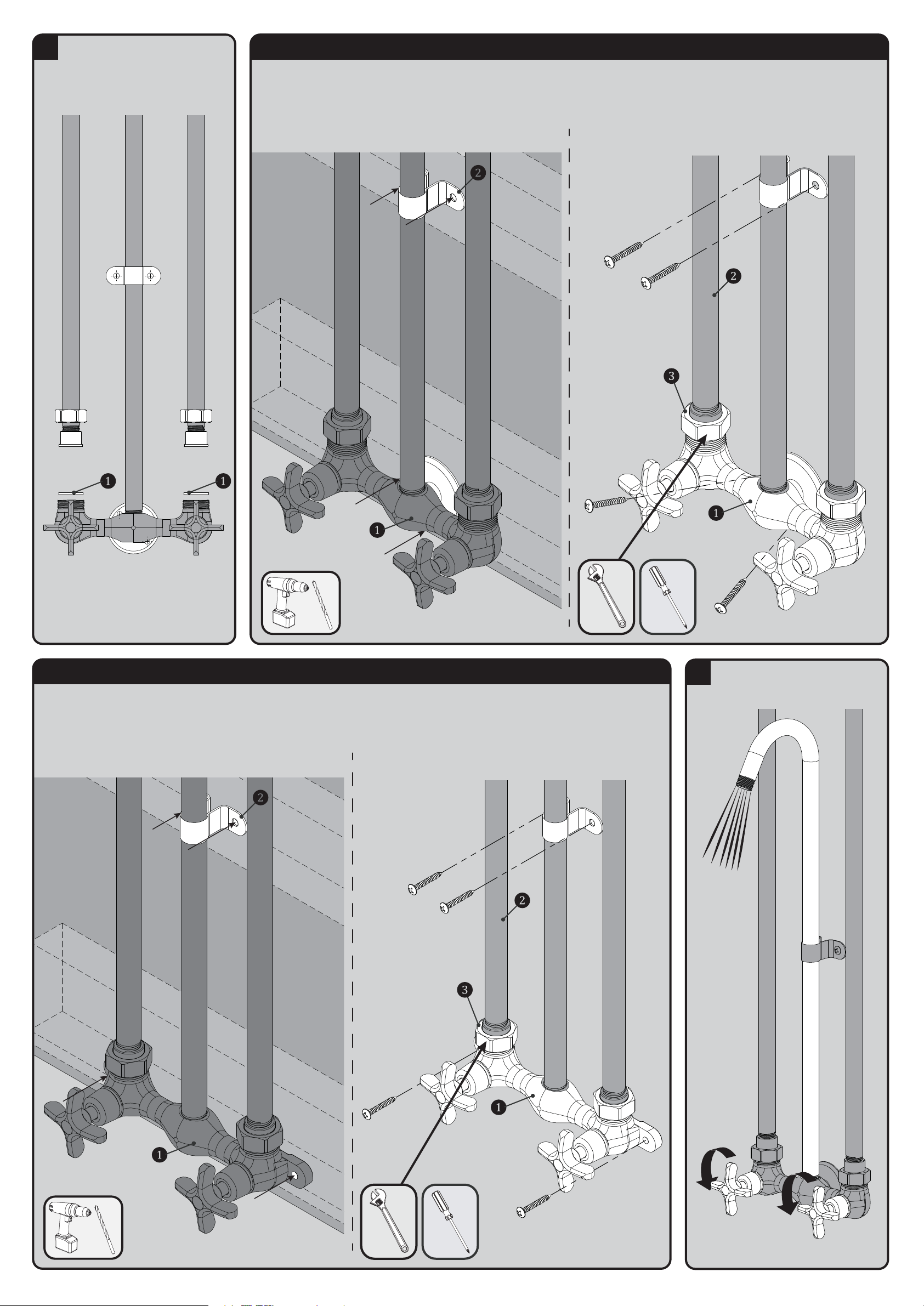
Place Rubber Washers (1) on inlets of Valve
Body and position body assembly up to Swivels
and tighten Coupling Nuts.
NOTE: Shower Arm Strap location optional.
Disconnect assembly from supply lines.
5 MOUNTING AND INSTALLATION OF ASSEMBLY WITH FLANGE
Verify that the mounting location and structure is capable of supporting
the product in use.
Hold assembly up against wall and mark location of mounting holes for
Valve Body (1) and Shower Arm Strap (2) referencing the rough-in
diagram contained in this document.
Drill starter holes at marked locations
Connect Valve Assembly (1) to Supply Lines (2) and tighten Coupling Nuts (3) with
wrench. Fasten body and strap to wall using four (4) Mounting Screws provided.
6 MOUNTING AND INSTALLATION OF ASSEMBLY WITH LUGS
Verify that the mounting location and structure is capable of supporting
the product in use.
Hold assembly up against wall and mark location of mounting holes for
Valve Body (1) and Shower Arm Strap (2) referencing the rough-in
diagram contained in this document.
Drill starter holes at marked locations
Connect Valve Assembly (1) to Supply Lines (2) and tighten Coupling Nuts (3) with
wrench. Fasten body and strap to wall using four (4) Mounting Screws provided.
7
Turn water supplies on and flush both Hot and
Cold sides of fitting.
Page 3
8
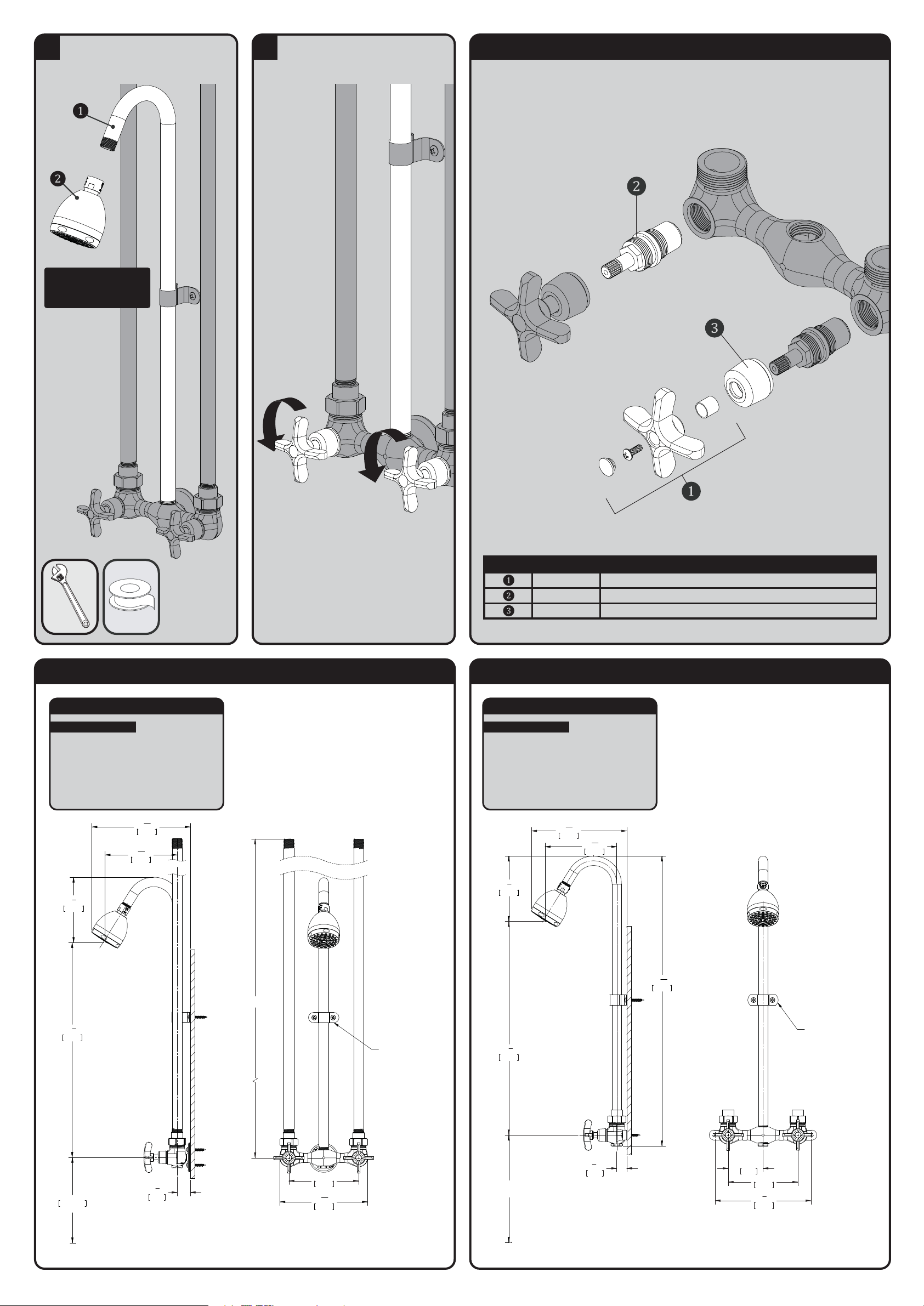
Apply sealant to threads of Shower Arm (1).
Screw Shower Head (2) onto Shower Arm (1)
and tighten with Pipe Wrench. Check all
connections for leaks.
NOTE: Shower head not
included with all models.
Shown for reference only.
9
Simply rotate the handles ¼ turn maximum to
operate the exposed shower.
SC-1210 / SC-1220 / SC-1230 / SC-1240 REPAIR PARTS
RPG04-0323-PC HANDLE REPAIR GROUP (INCLUDES HANDLE, SCREW, SLEEVE, & INDEXES)
RPG05-0532-CA VALVE CARTRIDGE GROUP (RED) W/ TRIM SLEEVE AND SCREW
RPG02-0141-PC TRIM COLLAR FOR VALVE
ITEM NO. PART NO. DESCRIPTION
SC-1210-AF ROUGH-IN DIAGRAM
SPEAKMAN
®
DIMENSIONS SUBJECT TO CHANGE WITHOUT NOTICE.
NOTES:
CONNECTIONS:
• Inlet: ½” NPT Male
• Outlets: ½“ NPT Male
Contractor to supply necessary inlet
connections.
6"
152mm
3'-0"
[0.91 Meters]
7
9
16
"
192mm
PIPE STRAP WITH SCREWS
(LOCATION OPTIONAL)
1
1
8
"
29mm
18
1
2
"
470mm
5
1
2
"
143mm
4'-6'
137 Meters
TO FLOOR
8
7
16
"
215mm
6
3
16
"
157mm
SC-1220-AF ROUGH-IN DIAGRAM
SPEAKMAN
®
DIMENSIONS SUBJECT TO CHANGE WITHOUT NOTICE.
NOTES:
CONNECTIONS:
• Inlet: ½” NPT Female
• Outlets: ½“ NPT Male
Contractor to supply necessary inlet
connections.
3"
76mm
6"
152mm
8
1
4
"
210mm
PIPE STRAP WITH SCREWS
(LOCATION OPTIONAL)
7
8
"
22mm
8
3
16
"
208mm
4"-6"
[1.37 Meters]
TO FLOOR
18
1
2
"
470mm
5
1
2
"
143mm
6
3
16
"
157mm
24
15
16
"
634mm
Page 4
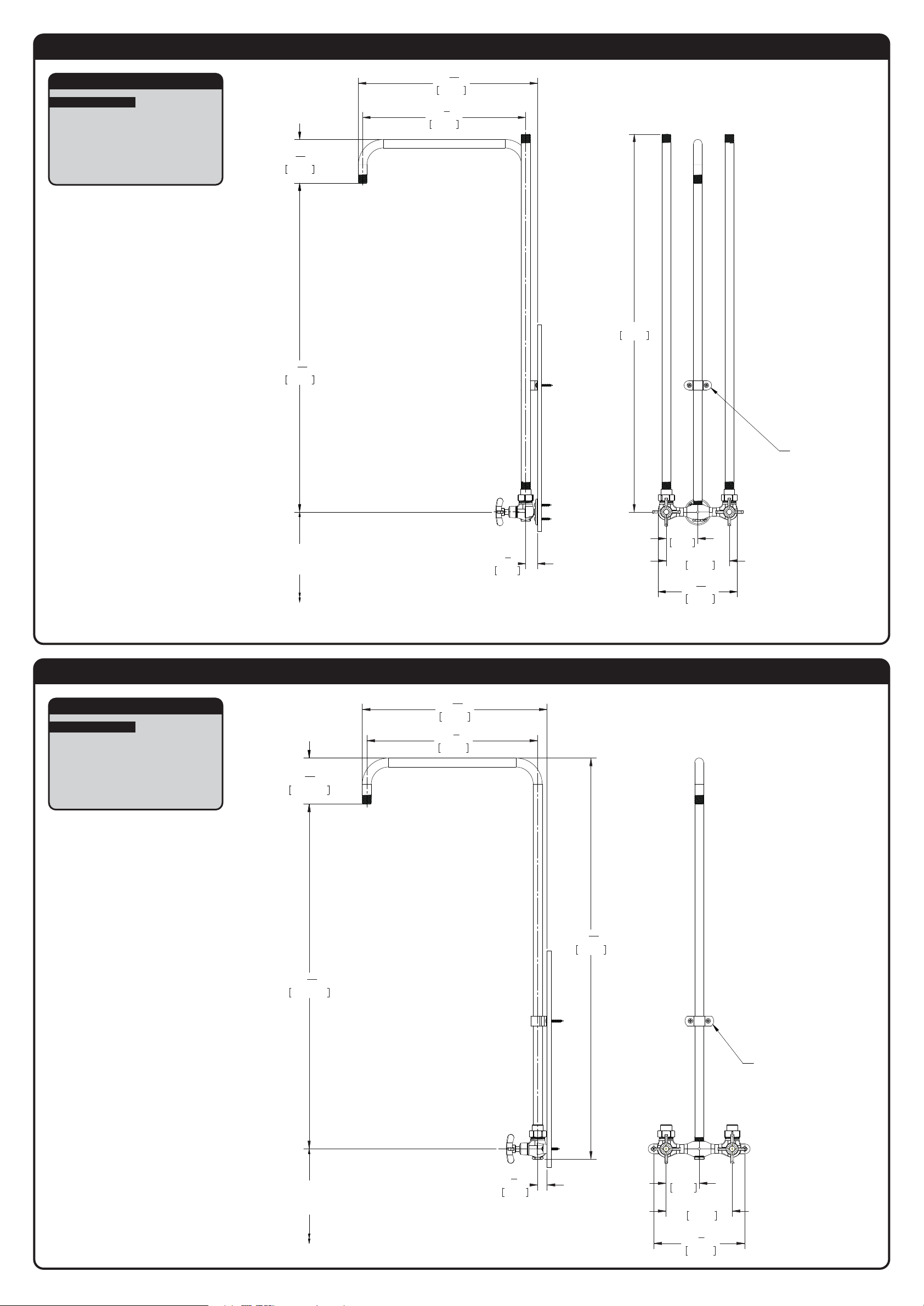
SC-1230-LH ROUGH-IN DIAGRAM
SPEAKMAN
®
DIMENSIONS SUBJECT TO CHANGE WITHOUT NOTICE.
NOTES:
CONNECTIONS:
• Inlet: ½” NPT Male
• Outlets: ½“ NPT Male
Contractor to supply necessary inlet
connections.
3"
76mm
6"
152mm
3'-0"
914mm
7
9
16
"
192mm
PIPE STRAP WITH SCREWS
(LOCATION OPTIONAL)
1
1
8
"
29mm
17
1
16
"
433mm
15
1
2
"
394mm
4
3
16
"
106mm
31
5
16
"
796mm
4'-6'
[1.37 METERS]
TO FLOOR
SC-1240-LH ROUGH-IN DIAGRAM
SPEAKMAN
®
DIMENSIONS SUBJECT TO CHANGE WITHOUT NOTICE.
NOTES:
CONNECTIONS:
• Inlet: ½” NPT Female
• Outlets: ½“ NPT Male
Contractor to supply necessary inlet
connections.
3"
76mm
6"
152mm
8
1
4
"
210mm
PIPE STRAP WITH SCREWS
(LOCATION OPTIONAL)
7
8
"
22mm
16
13
16
"
426mm
15
1
2
"
394mm
36
7
16
"
926mm
4
3
16
"
105.98mm
31
5
16
"
795.80mm
4'-6'
[1.37 METERS]
TO FLOOR
 Loading...