

Page 1

SPEAKMAN COMPANY
S-8700 Installation, Maintenance & Operation Instructions
SENSORFLO® BATTERY POWERED LOW SPOUT LAVATORY FAUCET
DESCRIPTION
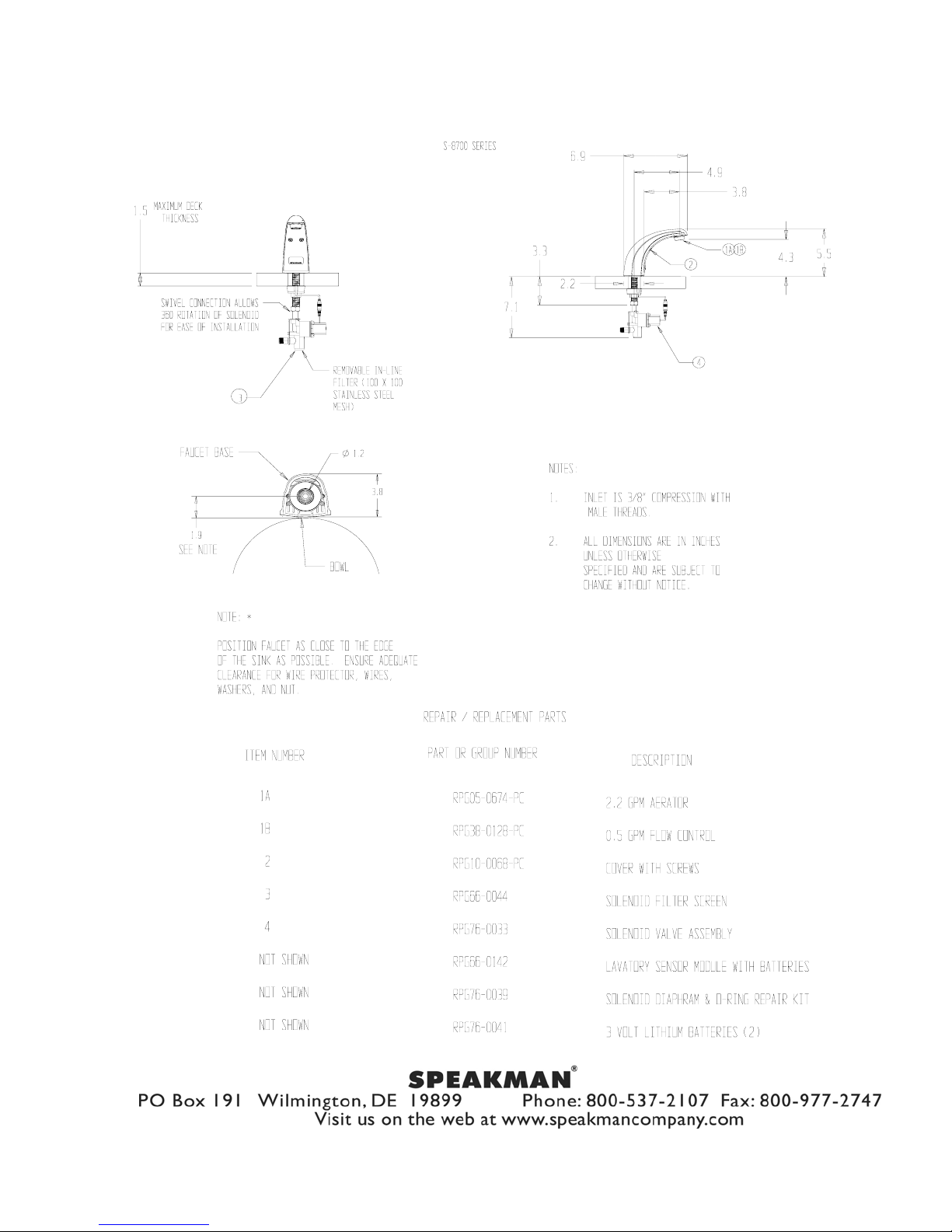
Speakman SENSORFLO faucet. Battery powered low spout lavatory sensor faucet. All metal spout assembly consists of
polished chrome plated removable cover and black powder coated chassis. Sensor module powered by two (2) 3-volt DC
lithium batteries with waterproof connectors housed above counter in faucet body. Low battery warning light. Solenoid with
built-in filter. Vandal resistant 60 second time out feature. Water conserving vandal resistant recessed aerator reduces water
flow to 2.2 GPM / 8.4 LPM to meet requirements of ANSI A112.18.1M for flow rates. ADA compliant. Note: 3/8’ Stainless
Steel Hoses are optional.
SPECIFICATIONS
INLET SUPPLY: 3/8” COMPRESSION WITH MALE THREADS
FLOW RATE: 2.2 GPM / 8.4 LPM
SHIPPING WEIGHT: 4.1 LBS
OPTIONS
BO – Vandal Resistant 0.5 GPM Flow Control
HS – 3 Stainless Steel Hoses for use with Tee or Mixer
HTS – 1 Stainless Steel Flexible Hose
GB – Vandal Resistant 1.5 GPM Aerator Outlet Device
LF – Vandal Resistant Laminar 2.2 GPM Flow Control
T – Tee with check valves
TMV – Under-Counter Thermostatic Mixing Valve with
check valves
VRS - Vandal Resistant Screws with Wrench
INSTALLATION
Remove cover from faucet body. Disconnect sensor module wires and remove module from faucet. Remove battery cover
from module and install new batteries, taking care to ensure correct polarity. Reassemble in reverse order as above. Make sure
module wire is plugged in and clipped into place on top of the module. Wires should be on the inside of cover screw bosses of
chassis to prevent pinching. Reattach cover to faucet with screws and wrench provided. Install vandal resistant aerator with
wrench provided. Ensure gasket is properly seated on bottom of faucet chassis. Carefully feed wire from faucet through deck
hole, mounting faucet on fixture. Attach notched wire guard (no tched end up) washer and lock nut onto faucet shank and
secure faucet to fixture. CAUTION: Sensor module wire must be inside channel of rubber wire guard to keep wire from being
pinched or cut when tightening washer and lock nut. Attach outlet of solenoid valve to shank of faucet. Attach supply to
solenoid valve using 3/8” compression fittings. DRY CONNECTIONS ONLY. Connect wire from faucet to solenoid valve.
With drain installed, turn on water and activate the faucet, checking for proper operation and all connections for leaks.
OPERATION
Speakman SENSORFLO faucets are thoughtfully designed for all in mind. Require no handles to turn, lift or push, water flows
only when hands are in the lavatory basin. Built in vandal resistant circuitry shuts off the water after continuous flow of
approximately 60 seconds. This feature prevents flood ing; water is easily turned on again by placing one’s hands under the
lavatory spout.
MAINTENANCE (CARE & CLEANING)
Your SENSORFLO faucet is designed and engineered in accordance with the highest quality and performance standard s. With
proper care it will provide years of trouble free service. Periodically the faucet will require some minor maintenance to keep it
performing at peak performance. The sensor module has a built-in low battery indicator light located in the center of the
rectangle infrared lens. This red light will come on when the faucet has approximately 30,000 on/off cycles remaining or 10%
of battery life. To replace the batteries follow the first portion of the installation instructions above. Periodically check the
solenoid filter for debris. If debris is present clean the filter toughly. The polished chrome finish of your faucet should be
cleaned using mild soap and warm water. Dry immediately with a soft, clean cloth for best results.
Page 2
92-2056 Rev. 3
 Loading...