

Page 1
INSTALLATION INSTRUCTIONS
SonicAir SA 2.1
Wireless Speaker Transmitter & Receiver
Page 2

SAFETY INSTRUCTIONS
CAUTION: To reduce the risk of electric
shock, do not remove cover (or back).
No user-serviceable parts inside. Refer
servicing to qualified service personnel.
• Explanation of Graphical Symbols
The lightning flash with arrowhead symbol, within an
equilateral triangle, is intended to alert you to the
presence of uninsulated “dangerous voltage” within
the product’s enclosure that may be of sufficient
magnitude to constitute a risk of electric shock to
persons.
The exclamation point within an equilateral triangle
is intended to alert you to the presence of important
operating and maintenance (servicing) instructions in
the literature accompanying the product.
APPLICABLE FOR USA, CANADA OR
WHERE APPROVED FOR USAGE
CAUTION: TO PREVENT ELECTRIC
SHOCK, MATCH WIDE BLADE PLUG TO
WIDE SLOT, INSERT FULLY.
ATTENTION: POUR EVITER LES CHOCS
ELECTRIQUES, INTRODUIRE LA LAME
LA PLUS LARGE DE LA FICHE DANS LA
BORNE CORRESPONDANTE DE LA PRISE
ET POUSSER JUSQU AU FOND.
FCC COMPLIANCE
This equipment has been tested and found to comply with the limits for a Class B digital device, pursuant to Part 15 of the
FCC Rules. These limits are designed to provide reasonable protection against harmful interference in a residential
installation.
This equipment generates, uses and can radiate radio frequency energy and, if not installed and used in accordance with
the instructions, may cause harmful interference to radio communications. However, there is no guarantee that interference
will not occur in a particular installation. If this equipment does cause harmful interference to radio or television reception,
which can be determined by turning the equipment off and on, the user is encouraged to try to correct the interference by
one or more of the following measures:
• Reorient or relocate the receiving antenna.
• Increase the separation between the equipment and receiver.
• Connect the equipment into an outlet on a circuit different from that to
which the receiver is connected.
• Consult the dealer or an experienced radio/TV technician for help.
FCC Caution: To assure continued compliance, any changes or modications to this unit not expressly approved by the
party responsible for compliance could void the user’s authority to operate the equipment. (Example - use only shielded
interface cables when connecting to computer or peripheral devices.)
1. Read these instructions.
2. Keep these instructions.
3. Heed all warnings.
4. Follow all instructions.
5. Do not use this apparatus near water.
6. Clean only with a damp cloth.
7. Do not block any ventilation openings. Install in accordance with
the manufacturer’s instructions.
8. Do not install near any heat sources such as radiators, heat registers,
stoves, or other apparatus (including amplifiers) that produce heat.
9. Do not defeat the safety purpose of the polarized or grounding-type
plug. A polarized plug has two blades with one wider than the other.
A grounding-type plug has two blades and a third grounding prong.
The wide blade or the third prong are provided for your safety. If the
provided plug does not fit into your outlet, consult an electrician for
replacement of the obsolete outlet.
10. Protect the power cord from being walked on or pinched particularly at plugs, convenience receptacles, and the point where they
exit from the apparatus.
11. Only use attachments/accessories specified by the manufacturer.
12. Use only with the cart, stand, tripod, bracket, or table specified by
the manufacturer, or sold with the apparatus. When a cart is used,
use caution when moving the cart/apparatus combination to
avoid injury from tip-over.
PORTABLE CART WARNING
13. Unplug this apparatus during lightning storms or when unused for
long periods of time.
14. Refer all servicing to qualified service personnel. Servicing is required
when the apparatus has been damaged in any way, such as
power-supply cord or plug is damaged, liquid has been spilled or
objects have fallen into the apparatus, the apparatus has been
exposed to rain or moisture, does not operate normally, or has been
dropped.
15. The apparatus shall not be exposed to dripping or splashing and
that no objects filled with liquids, such as vases, shall be placed on
the apparatus.
16. CAUTION: Servicing instructions are for use by qualified service personnel only. To reduce the risk of electric shock, do not perform any
servicing other than that contained in the operating instructions
unless you are qualified to do so.
17. WARNING: To reduce the risk of fire or electric shock, do not expose
this apparatus to rain or moisture.
FCC Radiation Exposure Statement: this equipment complies with FCC radiation exposure limits set forth for an uncontrolled
environment. This equipment should be installed and operated with a minimum distance of 20 centimeters between the
radiator and your body.
This transmitter must not be co-located or operating in conjunction with any other antenna or transmitter.
the antenna used for this transmitter must be installed to provide a separation distance of at least 20 centimeters from all
persons and must not be co-located or operating in conjunction with any other antenna or transmitter.
2 3
Page 3

TABLE OF CONTENTSNOTES
SAFETY INSTRUCTIONS ......................................................................................................................... 2
FCC COMPLIANCE .............................................................................................................................. 3
NOTES ................................................................................................................................................... 4
TABLE OF CONTENTS ............................................................................................................................ 5
INTRODUCTION .................................................................................................................................... 6
WHAT’S INCLUDED ............................................................................................................................... 7
SA 2.1 FEATURES .................................................................................................................................. 8
SA 2.1 Transmitter ............................................................................................................................... 8
SA 2.1 Receiver ................................................................................................................................ 10
SA 2.1 Remote Control .................................................................................................................... 12
INSTALLATION .................................................................................................................................... 13
SA 2.1 Transmitter/Receiver Location & Transmission Range .................................................... 13
Mounting the SA 2.1 Receiver ...................................................................................................... 14
CONNECTIONS ............................................................................................................................... 16
SA 2.1 Transmitter/Receiver Connections .................................................................................. 16
Speaker Level Connections (SA 2.1 Transmitter) ....................................................................... 16
Speaker Level Connections (SA 2.1 Receiver) .......................................................................... 16
Line Level Connections (SA 2.1 Transmitter) .............................................................................. 17
Subwoofer Connections (SA 2.1 Receiver)................................................................................ 17
Aux In Connections (SA 2.1 Receiver) ........................................................................................ 18
Final Setup ...................................................................................................................................... 18
Position the Transmitter and Receiver ........................................................................................ 18
Antenna ......................................................................................................................................... 18
Power Supply Connections ......................................................................................................... 18
OPERATING THE SA 2.1 ...................................................................................................................... 19
Turning the SA 2.1 ON/OFF ............................................................................................................. 19
Front Panel LEDs ............................................................................................................................... 19
Volume Control ................................................................................................................................ 20
Input/Source Selection ................................................................................................................... 20
ID Codes ........................................................................................................................................... 21
SPECIFICATIONS ................................................................................................................................ 22
LIMITED 2-YEAR WARRANTY .............................................................................................................. 23
4 5
Page 4
WHAT’S INCLUDEDINTRODUCTION
Congratulations and thank you for purchasing the SpeakerCraft SonicAir SA 2.1 Wireless Speaker
Transmitter and Receiver System!
The SA 2.1 solves the age-old problem of how to put speakers where you want them without having
unsightly speaker wire run around baseboards, across the oor or having to pull them through walls.
The SA 2.1 Transmitter can connect to just about any audio source. It then broadcasts audio content
as wireless RF (radio frequency) signals to the SA 2.1 Receiver, that can be placed up to seventy feet
away (depending upon the local RF environment).
The SA 2.1 Transmitter features both stereo line level and speaker level audio inputs. The Pre-Amp and
Speaker Level Inputs both feature audio sensing circuitry that automatically turns the SA 2.1 system
on when audio input signals are detected. The system will automatically turn off (standby) when no
audio signals have been detected for more than ten minutes.
In addition to regular stereo speaker applications, the speaker level inputs provide convenience for
A/V system rear speaker placement in surround sound systems. The SA 2.1 Transmitter can be connected to the rear channel speaker terminals on the A/V receiver and then broadcast the rear channel speaker signals to the SA 2.1 Receiver, located with the rear channel speakers. This eliminates having unsightly and potentially hazardous speaker wires run around baseboards or across the oor.
The SA 2.1 system also increases the exibility of an audio system from a single room system to a multiroom system. With an audio receiver directly connected to the main room speakers in a normal conguration, the audio receiver ‘B’ speakers or pre-amp output can be connected to the SA 2.1 Transmitter for broadcast to the SA 2.1 Receiver in the second room, creating a multi-room audio system
without having to pull wires!
The SA 2.1 Receiver adds additional exibility with its local Auxiliary Input. With the SA 2.1 system
congured as a multi-room system, this line level, stereo 3.5mm mini jack allows connection of a local source in the remote room. This allows selection of the ‘house’ system audio source or the local
source which could be a CD or MP3 player, video game, computer, cable box, or any other audio
source with a line level output. The SA 2.1 Receiver is controlled locally with the SA 2.1 IR Remote, allowing independent source selection and volume/mute control in the remote room.
The SA 2.1 Receiver has a solid built-in 50 Watts per channel amplier that will make any audio source
sound great when driven through appropriately rated 8 ohm speakers.
WHAT’S INCLUDED
Transmitter
1 - SA 2.1 Transmitter
1 - 18VDC 400mA Power Supply
Receiver
1 - SA 2.1 Receiver
1 - 24VDC 4.75A Power Supply
1 - SA 2.1 IR Remote
1 - SA 2.1 Installation Instructions
SA 2.1 FEATURES
Transmitter
Inputs/Connections
Speaker Level - 4 ve-way binding posts
Pre-Amp Level - 2 RCA jacks
Power - 2.1mm coaxial jack
Status
Multi-color front panel LED
Transmission Range
Up to 70 feet depending upon RF environment
ID Code
Four position RF channel selector
Receiver
Audio Amplier
50 Watts per channel x 2
Outputs/Connections
Speaker Level - 4 ve-way binding posts
Sub Out - 3.5mm stereo mini jack
Power - 2.1mm coaxial jack
Aux In
For those who want some extra kick, the SA 2.1 Receiver also features a full-band Sub Out that can
be connected to a subwoofer with a line level input, and variable level and crossover controls. This
‘wireless subwoofer’ application allows optimizing main room subwoofer placement, without the
restriction of having to run unsightly audio cable to the sub. The SA 2.1 Receiver Sub-Out adds that
same exibility to multi-room applications, allowing not only the addition of a subwoofer to the second room, but unrestricted placement for optimum performance and convenience. The pre-installed
Receiver Clip and included Mounting Bracket allow convenient and inconspicuous mounting of the
SA 2.1 Receiver directly to a powered subwoofer.
The SpeakerCraft SonicAir SA 2.1 Wireless Speaker Transmitter and Receiver System gives you music
where you want it...not just where the speaker wires are.
Please read and follow the instructions in this guide to assist in proper installation, connection and use
of the SpeakerCraft SonicAir SA 2.1 Wireless Speaker Transmitter and Receiver System.
6 7
Local Audio Input
Aux In - 1 stereo 3.5mm mini jack
Status
Multi-color front panel LED
ID Code
Four position RF channel selector
IR Remote
Volume
Mute
Input
Page 5

SONICAIR SA 2.1 FEATURES
SONICAIR SA 2.1 FEATURES
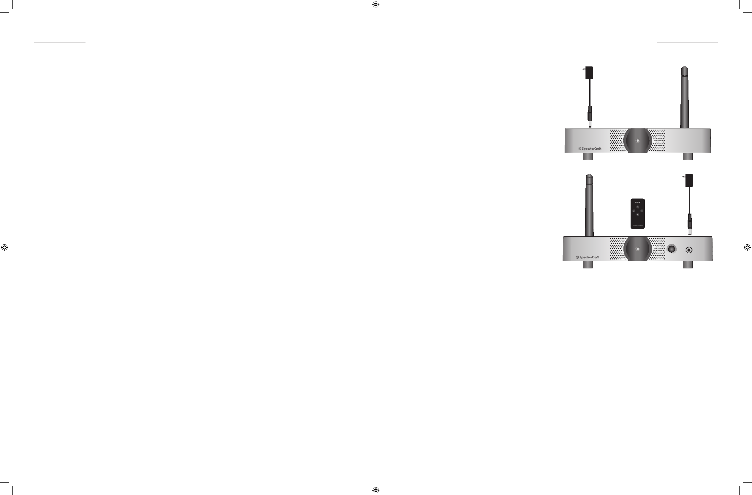
SA 2.1 Transmitter
The SA 2.1 Transmitter connects to the line
level audio or speaker level outputs on
an A/V or audio receiver, CD player, MP3
player, video game, computer audio card
or other audio device to broadcast stereo
audio signals to speakers in the main room
or another location when running speaker
wire is not convenient or possible.
1
The SA 2.1 Transmitter is located with the
audio source and positioned for optimum
performance and must be connected to an
AC outlet.
The SA 2.1 Transmitter converts audio content to RF (Radio Frequency) signals and
Figure 1 SA 2.1 Transmitter Front Panel Features
broadcasts the RF signals to the SA 2.1 Receiver, which can be located up to 70 feet away, depending upon
local conditions. (Metal construction materials, large metal objects and RF interference from microprocessors
and other wireless devices.)
The SA 2.1 Receiver converts the RF signals back to audio content and outputs amplied speaker level audio to
drive the connected speakers. The SA 2.1 Receiver also features a full-band, line level sub output that can be
connected to the LINE IN on a powered subwoofer with variable crossover and level controls or power amplier
to drive more speakers.
Volume for the speakers connected to the SA 2.1 Receiver may be controlled with the included SA 2.1 IR Remote or the audio receiver remote or front panel controls, depending upon connections and conguration.
See section: Operating the SA 2.1/Volume Control for additional information.
SA 2.1 Transmitter Front Panel Features
1. POWER LED - This multicolored LED has multiple modes to indicate SA 2.1 Transmitter status.
SOLID BLUE - SA 2.1 system is active. Transmitter and Receiver are communicating normally. (RF lock.)
SLOW BLUE FLASH - Transmitter and Receiver are not communicating normally. (No RF lock. Check
power connections and placement of devices that may be causing interference.) Also see section:
Operating the SA 2.1/ID Codes.
SOLID RED - Indicates Standby condition. (Automatic function. No audio signal sensed for more than 10
minutes.)
SA 2.1 Transmitter Rear Panel Features
2. ANTENNA - Attached antenna. Position
fully vertical (up/down) for optimum
performance once SA 2.1 Transmitter is
in place.
3. DC18V/400mA POWER JACK - One
2.1mm coaxial jack. Connect to the
included power supply.
4. ID CODE - Four position slide switch.
Allows changing channels if RF interference is affecting SA 2.1 performance at
the factory setting.
NOTE: If it is necessary to change the ID
Code, be sure to change the ID Code on
both the Transmitter and Receiver to the
same setting.
5. PRE-AMP INPUTS - Two RCA jacks. Connect to the stereo line level analog audio outputs on the audio
source to be broadcast. This can be the Pre-Out on an audio receiver such as the SpeakerCraft VITAL 710,
the Zone 2 Pre-Out on an A/V receiver such as the SpeakerCraft VITAL 910 or the line level audio output on
a CD player, MP3 Player, video game, computer audio card, etc.
6. SPEAKER LEVEL INPUTS - Four ve-way binding posts. Connect to the speaker level outputs on an A/V or audio receiver. MAX INPUT VOLTAGE: 14.5 V AC RMS.
AUDIO RECEIVER (Single Room Stereo) - Connect to the ‘A’ speaker terminals on an audio receiver such
as the SpeakerCraft VITAL 710, to broadcast audio to the main room stereo speakers when it is not convenient to run speaker wires from the audio receiver to the speakers.
AUDIO RECEIVER (Multi-room Stereo) - Connect to the ‘B’ speaker terminals on an audio receiver such
as the SpeakerCraft VITAL 710, to broadcast audio to a remote speaker pair for multi-room audio, when
it is not convenient to run speaker wires to the remote room. (The multi-room speakers can be turned
ON/OFF by selecting/deselecting the ‘B’ speakers on the audio receiver.)
NOTE: Do not connect the ‘A’ and ‘B’ speakers to the SA 2.1 Speaker Level Inputs at the same time. This
will cause severe damage to the SA 2.1 Transmitter and the audio receiver.
A/V RECEIVER (Surround Speakers)- Connect to the ‘Surround left and right’ or ‘Surround Back left and
right’ speaker terminals, as appropriate, on an A/V receiver such as the SpeakerCraft VITAL 910, to
broadcast surround audio channels to the surround speakers when it is not convenient to run speaker
wires to the surround speakers.
NOTE: If using the SA 2.1 system to broadcast surround speaker channels, connecting a source to the
SA 2.1 Receiver Aux In is not recommended. Surround speaker levels should be set to specic levels that
are in balance with the front speakers. Selecting the source connected to the Aux In and adjusting the
volume for that source will adversely affect the front/rear speaker balance when the surround speakers
are selected. Use normal setup procedures, per A/V receiver manufacturer’s instructions, for setup of
surround speaker levels/delays, once SA 2.1 system is connected and powered up.
2 3 4 5 6
DC18V/400mA
ID CODE
Figure 2 SA 2.1 Transmitter Rear Panel Features
1
3
2
4
PRE-AMP INPUTS
R L
SA 2.1 Transmitter
SPEAKER LEVEL INPUTS
A/V RECEIVER (Second Zone) - Connect the ‘Zone 2’ speaker terminals on an appropriately featured
surround receiver such as the SpeakerCraft VITAL 910, to broadcast second zone audio to a remote
speaker pairs in a second zone, when it is not convenient to run speaker wires to the second zone’s
rooms. (A second zone allows two different audio sources to play at the same time in different rooms.
Multi-room has the same source playing in both rooms.)
NOTE: Second Zone conguration typically requires some conguration in the A/V receiver setup. Please
refer to the A/V receiver manual for additional information.
8 9
Page 6

SONICAIR SA 2.1 FEATURES
SONICAIR SA 2.1 FEATURES
SA 2.1 Receiver
The SA 2.1 Receiver connects to speakers
located where running speaker wires from
an A/V or audio receiver is not convenient
or possible, or when driving speakers for
an audio source such as a CD player, MP3
player, video game, computer audio card
or other audio device that is connected to
the SA 2.1 Transmitter.
The SA 2.1 receiver should be located near
the remote speakers, positioned for optimum performance, and must be connected to an AC outlet.
The SA 2.1 Receiver receives RF (Radio Frequency) signals broadcast from the SA 2.1
Figure 3 SA 2.1 Receiver Front Panel Features
Transmitter, which can be located up to 70
feet away, depending upon local conditions. (Metal construction materials, large metal objects and RF interfer-
ence from microprocessors and other wireless devices.)
The SA 2.1 Receiver converts the RF signals to audio content and outputs amplied speaker level audio to drive
the connected speakers. The SA 2.1 also outputs a full-band, line level subwoofer channel, that can be connected to the LINE IN on a powered subwoofer with variable crossover and level controls.
Volume for the speakers connected to the SA 2.1 Receiver may be controlled with the included SA 2.1 IR Remote or the audio receiver remote or front panel controls, depending upon connections and conguration.
See section: Operating the SA 2.1/Volume Control for additional information.
1 2 3
Aux In
SA 2.1 Receiver Rear Panel Features
4. SUB-OUT - One 3.5mm stereo mini jack.
The SUB-OUT is a full-band (20-20kHz) left
and right channel line level output. This
output can be used as a wireless ‘LFE’
channel or as wireless ‘full range’ channels.
LFE - Using a mono mini to RCA cable,
connect to the LFE IN jack on a powered subwoofer. Only the frequencies
output by the A/V Receiver LFE OUT
(and broadcast from the SonicAir Transmitter) will be output. The subwoofer
crossover controls will have no affect on
the subwoofer LFE IN.
Subwoofer - Using a stereo 3.5mm mini
to RCA cable, connect to the L & R LINE INs on a powered subwoofer with variable crossover and level
controls. Do not connect to the LFE Input on the subwoofer. The subwoofer LFE input is not adjustable with its
crossover control. Without setting a crossover point on the sub, the sub will output higher frequency content
with less than desirable results. Please refer to the subwoofer owners manual for instructions on setting the
subwoofer crossover point and volume.
5. SPEAKER LEVEL OUTPUTS - Four ve-way binding posts. Connect to the speaker terminals on the speakers to
be driven by the SA 2.1 Receiver. POWER OUTPUT: 50 WATTS PER CHANNEL; MAX LOAD: 4 OHMS.
AUDIO RECEIVER (Single Room Stereo) - If connecting the ‘A’ speakers on audio receiver, connect to
the main room left and right speaker terminals.
4 5 6 7 8
SUB OUT
SA 2.1 Receiver
SPEAKER LEVEL OUTPUTS
Figure 4 SA 2.1 Receiver Rear Panel Features
ID CODE
1
DC 24V/4.75A
3
4
2
ANT
SA 2.1 Receiver Front Panel Features
1. POWER LED - This multicolored LED has multiple modes to indicate SA 2.1 Receiver status.
SOLID BLUE - SA 2.1 system is active. Transmitter and Receiver are communicating normally. (RF lock.)
SLOW BLUE FLASH - Transmitter and Receiver are not communicating normally (No RF lock. Check power
connections and placement of devices that may be causing interference.) Also see section: Operating
the SA 2.1/ID Codes.
FAST BLUE FLASH - SA 2.1 Receiver is sensing commands from an IR remote control.
SOLID RED - Indicates Standby condition. (Automatic function. No audio signal sensed for more than 10
minutes.)
SOLID ORANGE - The SA 2.1 Receiver Aux Input is selected.
SLOW ORANGE FLASH - SA 2.1 Receiver Speaker Level and Sub-Outs are muted.
FAST ORANGE FLASH - SA 2.1 Receiver is sensing commands from an IR remote control when the Aux
Input is selected.
2. IR SENSOR - IR eye, ‘sees’ the IR commands from the included SA 2.1 IR Remote or a universal programmable remote to control the SA 2.1 Transmitter/Receiver system.
AUDIO RECEIVER (Multi-room Stereo) - If the Transmitter is connected to the ‘B’ speaker terminals on an
audio receiver such as the SpeakerCraft VITAL 710 for multi-room audio, connect to the left and right
speaker terminals on the remote speaker pair. (The second room speakers can be turned ON/OFF by
selecting/deselecting the ‘B’ speakers on the audio receiver.)
A/V RECEIVER (Surround Speakers)- If connecting the rear channel speakers on a surround receiver,
such as the SpeakerCraft VITAL 910, connect to the ‘Surround left and right’ speaker terminals (5.1 conguration) or ‘Surround Back left and right’ speaker terminals (7.1 conguration).
A/V RECEIVER (Second Zone) - If connecting second zone speakers on an appropriately featured sur-
round receiver, such as the SpeakerCraft VITAL 910, connect to the ‘Second Zone’ left and right speaker
terminals.
NOTE: Second Zone conguration typically requires some conguration in the A/V receiver setup. Please
refer to the A/V receiver manual to for additional information.)
6. ID CODE - Four position slide switch. Allows changing channels if RF interference is affecting SA 2.1 performance at the factory setting.
NOTE: If it is necessary to change the ID CODE, be sure to change the ID Code on both the Transmitter and
Receiver to the same setting.
7. DC24V/4.75A POWER JACK - One 2.1mm coaxial jack. Connect to the included DC24V/4.75A power supply.
8. ANTENNA - Attached antenna. Position fully vertical (up/down) for optimum reception once SA 2.1 Receiver
is in place.
3. AUX IN - One 3.5mm stereo mini jack. Connect to a local source such as a CD player, MP3 player, video
game, cable box, computer audio card or other audio device.
10 11
Page 7

SONICAIR SA 2.1 FEATURES
INSTALLATION
SA 2.1 Remote Control
1
The SA 2.1 IR Remote Control provides
simple control of the SA 2.1 Wireless Speaker
System. The remote must be in ‘line-of-sight’
to the SA 2.1 Receiver IR Sensor when sending commands for proper control.
The commands from the SA 2.1 Remote
23
can be learned by a ‘universal’ remote, for
control of the SA 2.1 and other system components. The SA 2.1 Receiver can be hidden
in a cabinet or closet and controlled with an
IR Repeater system, provided the SA 2.1 Receiver is properly receiving signals from the
SA 2.1 Transmitter and the SA 2.1 Receiver
can be connected to the driven speakers.
(See www.speakercraft.com; navigate to:
Figure 5 SA 2.1 Remote Front Panel Features
Products/Control Systems/SmartPath)
SA 2.1 Remote Control Features
1. VOLUME UP/DOWN - Press the button to increase volume. Press the button to decrease volume.
2. INPUT - Press this button to select the Aux In jack on the SA 2.1 Receiver Front Panel. (The SA 2.1 Receiver LED
will illuminate solid orange.) Press the button again to select the source connected to the SA 2.1 Transmitter.
(The SA 2.1 Receiver LED will illuminate solid blue.)
3. MUTE - Press this button to mute the SA 2.1 audio output, (there will be no sound coming from the connected speakers). The LED on the SA 2.1 Receiver will slowly ash orange. Press again to un-mute. The LED on the
SA 2.1 Receiver Front Panel will illuminate solid blue, (source from Transmitter) or orange (source connected
to Receiver Aux IN).
Remote Control Battery Replacement CAUTION
When replacing the lithium battery in the remote, make sure that the replacement battery is inserted in correct
polarity. Place the battery so that its positive (+) side faces up with the tray held so that the surface with the dot
and (+) is facing up.
SA 2.1 Transmitter/Receiver Location & Transmission Range
Deck
Aux In
SA 2.1 Receiver
Out of Range
Master Suite
Dining Room
Back Yard
Area
SA 2.1
Transmitter
WIRELESS COVERAGE AREA 70’ RADIUS
Living
Room
Patio
Bedroom 2
SA 2.1 Receiver
In Range
Master
Bath
Kitchen
Aux In
Full
Bath
Closet
Pantry
Half
Bath
Den
Entry
Bedroom 1
Garage
Front Yard
Area
Remote Control Battery Installation
Push small tab toward
battery slot.
Pull battery drawer out. Insert battery with “+” side up,
and slide drawer back into remote.
CAUTION: DANGER OF EXPLOSION IF BATTERY IS INCORRECTLY REPLACED.
REPLACE ONLY WITH THE SAME OR EQUIVALENT TYPE (CR2032).
WARNING: DO NOT EXPOSE BATTERIES TO EXCESSIVE HEAT SUCH AS DIRECT SUNLIGHT, FIRE OR THE LIKE.
Dispose of dead batteries in accordance with local regulations.
12 13
Figure 6 SA 2.1 Transmission/Reception Range
The SA 2.1 System has a transmission/reception range of approximately seventy feet. The actual performance
will vary depending upon local conditions. Metal construction materials, large metal objects such as refrigerators and RF interference from microprocessors and other wireless devices can all affect range performance.
Both the Transmitter and Receiver must be located near and connected to AC outlets for power.
1. When locating the SA 2.1 Transmitter and SA 2.1 Receiver, be sure both are within the transmission/reception
range of the system as shown in Figure 6.
2. Do not connect the power supplies at this point. Power supplies will be connected after all other connections have been made.
Page 8

INSTALLATION
DC 24V/4.75A
ANT
SUB OUT
1
2
3
4
ID CODE
SA 2.1 Receiver
SPEAKER LEVEL OUTPUTS
Push the SA 2.1 Receiver
Down so the Receiver Clip
slides into the
Mounting Bracket
Subwoofer or
Equipment Cabinet
Side Wall
Receiver Clip
Mounting Bracket
Position Antenna Full Vertical
INSTALLATION
Mounting the SA 2.1 Receiver (Optional)
The included Mounting Bracket can be used
to conveniently and inconspicuously mount
the SA 2.1 Receiver directly to a subwoofer
or cabinet sidewall.
This allows greater exibility in subwoofer
placement options by eliminating the restriction of the sub having to be directly hardwired to the A/V Receiver.
Attaching the SA 2.1 Receiver to the sub
also creates a cleaner looking setup by
eliminating the audio cable running around
the baseboards from the A/V Receiver to
the sub.
All SpeakerCraft powered subwoofers feature audio sensing that will automatically
turn the sub ON/OFF (standby) when audio
signals are output from the SA 2.1 Receiver.
Additionally, all SpeakerCraft powered subs
have variable volume and crossover controls for optimization of low frequency audio
signals.
Receiver Clip
3. Align the SA 2.1 Receiver Clip over the
Mounting Bracket as shown in Figure 9.
4. Carefully slide the SA 2.1 Receiver Clip
into the Mounting Bracket.
5. Position subwoofer to its normal location.
6. Extend the SA 2.1 Receiver Antenna to a
full vertical position as shown in Figure 9.
7. Proceed to Connection Sections.
8. Do not reconnect AC power to the sub
until all system connections are complete.
9. After all connections have been made
and conrmed and the sub has been
reconnected to AC power, set the subwoofer Power Switch to AUTO (or other
audio sensing position as dened by
brand). Please refer to the Subwoofer’s
Owners Manual for additional information.
Be sure that the subwoofer is turned OFF and
disconnected from AC power before attaching the Mounting Bracket.
1. Align the Mounting Bracket in a proper
vertical position on the subwoofer or
cabinet sidewall as shown in Figure 8.
2. Attach the Mounting Bracket to the subwoofer or cabinet sidewall as shown in
Figure 8. (Screws not included.) Be sure
to use appropriate wood screws that will
rmly attach the Mounting Bracket, but
will not protrude out the other side of the
mounting surface. Do not overtighten
the screws.
Figure 7 SA 2.1 Receiver Clip
Attach Mounting Bracket to
Subwoofer or Equipment
Cabinet side wall.
(Screws not included.)
Figure 9 Mounting the SA 2.1 Receiver
Figure 8 SA 2.1 Receiver Mounting Bracket
14 15
Page 9
CONNECTIONS
SA 2.1 Transmitter/Receiver Connections
CONNECTIONS
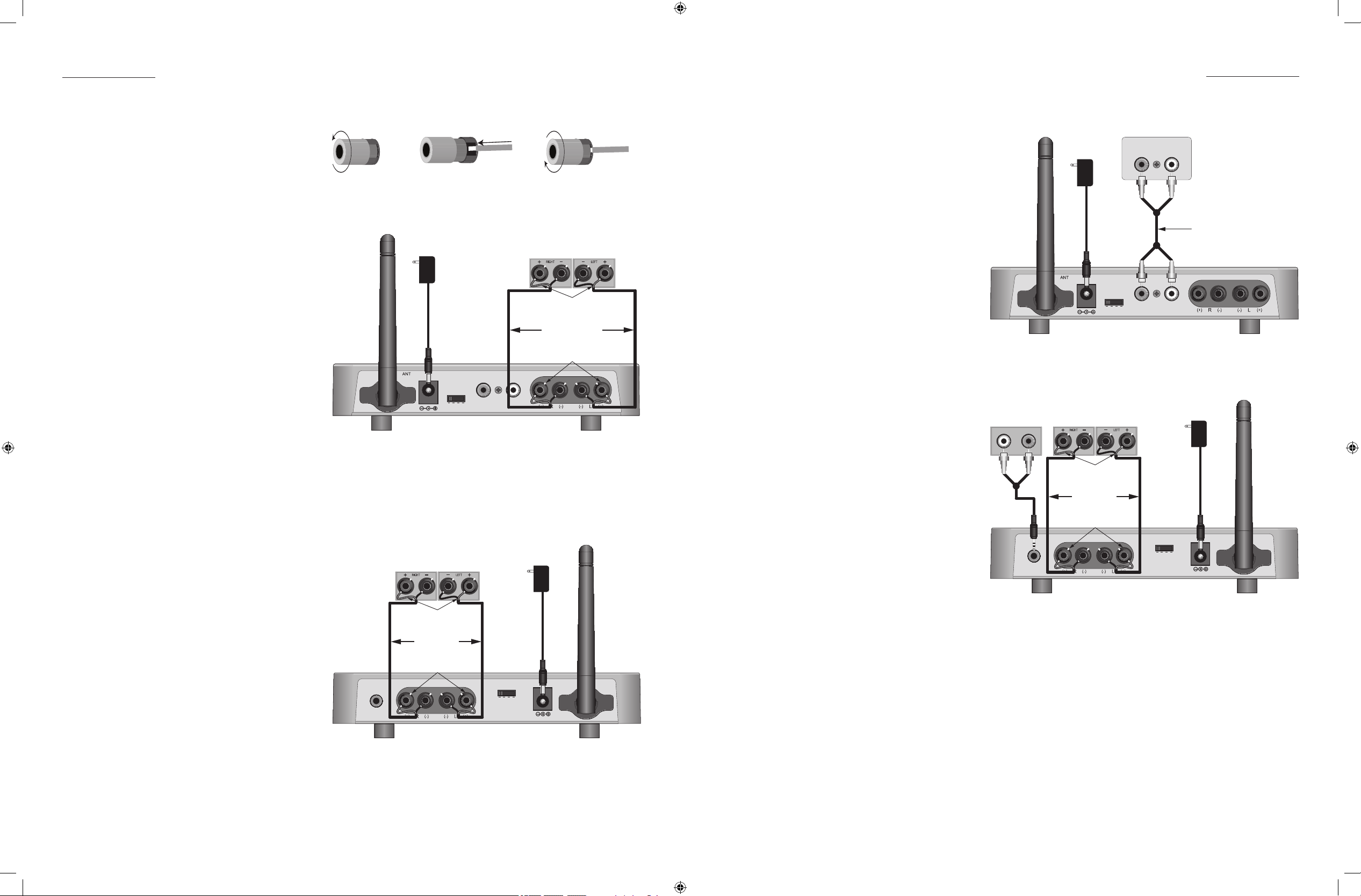
Speaker Level Connections (SA 2.1 Transmitter)
NOTE: Be sure all system components are turned
OFF and disconnected from AC power before
making any connections to avoid potential
damage to the equipment and electrical
shock.
1. Use 16AWG (min) 2-conductor stranded
speaker wire for all speaker connections.
2. Strip approximately 1/2 to 3/4 of an inch
off the ends and twist the strands together
so there are no loose ends that can cause
shorts.
3. If connecting the SA 2.1 Transmitter to the
speaker level output on the audio receiver/
amplier, connect to the audio receiver/amplier speaker out terminals as appropriate.
Please refer to the receiver/amplier owners
manual for additional information.
4. Loosen the SA 2.1 Transmitter Speaker Level
Input Terminals as shown in Figure 10 so
there is enough room between the post and
the collar to feed the stripped wire through
without damaging the strands.
5. Tighten the post to secure the wire.
6. Repeat for left and right speakers, + and -.
7. Conrm connections and polarity on both
the audio receiver and SA 2.1 Transmitter.
Speaker Level Connections (SA 2.1 Receiver)
1. Loosen the SA 2.1 Receiver Speaker Level
Output Terminals as shown in Figure 10 so
there is enough room between the post and
the collar to feed the stripped wire through
without damaging the strands.
2. Tighten the post to secure the wire.
3. Repeat for left and right speakers, + and -.
4. Conrm connections and polarity.
5. Connect the speaker wires to the appropri-
ate + and - terminals on the left and right
speakers.
6. Conrm connections and polarity.
Figure 10 Bare Wire Connections
18VDC 400mA
Power Supply
To unswitched outlet
Receiver/Amplifier
Speaker Out Terminals
White Stripe
To Positive
16AWG Stranded
(minimum)
Speaker Wire
White Stripe
To Positive
DC18V/400mA
ID CODE
3
2
1
4
PRE-AMP INPUTS
R L
SA 2.1 Transmitter
SPEAKER LEVEL INPUTS
Figure 11 SA 2.1 Transmitter Speaker Level Input Connections
SPEAKER LEVEL INPUT MAX INPUT VOLTAGE:
14.5V AC RMS
24VDC 4.75A
Power Supply
To unswitched outlet
ID CODE
3
4
2
1
DC 24V/4.75A
ANT
SUB OUT
SA 2.1 Receiver
Speaker Terminals
White Stripe
To Positive
16AWG Stranded
(minimum)
Speaker Wire
White Stripe
To Positive
SPEAKER LEVEL OUTPUTS
Figure 12 SA 2.1 Receiver Speaker Level Output Connections
SPEAKER LEVEL OUTPUT POWER: 50 WATTS PER
CHANNEL; MAX LOAD: 4 OHMS
Line Level Connections (SA 2.1 Transmitter)
NOTE: Be sure all system components are turned
OFF and disconnected from AC power before
making any connections to avoid potential
damage to the equipment and electrical
shock.
1. Using a stereo RCA-RCA patch cable with
gold ends, connect the left and right xed
line level audio outputs of a CD player, MP3
player, etc; or variable pre-amp level output
of an audio receiver to the left and right
Pre-Amp Inputs on the SA 2.1 Transmitter as
shown in Figure 13.
Subwoofer Connections (SA 2.1 Receiver)
1. The SUB-OUT is a full-band (20-20kHz) left and
right channel line level output. This output
can be used as a wireless ‘LFE’ channel or
as wireless ‘full range’ channels.
LFE - Using a mono mini to RCA cable, con-
nect to the LFE IN jack on a powered subwoofer. Only the frequencies output by the
A/V Receiver LFE OUT (and broadcast from
the SonicAir Transmitter) will be output. The
subwoofer crossover controls will have no
affect on the subwoofer LFE IN.
NOTE: A/V Receiver LFE OUT should be con-
nected to the Sonic Air Transmitter Left Preamp Input.
Subwoofer - Using a stereo 3.5mm mini to
RCA cable, connect to the L & R LINE INs
on a powered subwoofer with variable
crossover and level controls. Do not connect to the LFE Input on the subwoofer. The
subwoofer LFE input is not adjustable with its
crossover control. Without setting a crossover point on the sub, the sub will output
higher frequency content with less than desirable results. Please refer to the subwoofer
owners manual for instructions on setting the
subwoofer crossover point and volume.
NOTE 2: If using the Sub Out connection, use
of a subwoofer with audio sensing is recommended. This will allow the sub to turn ON
automatically when audio signal is present
on the SA 2.1 Receiver Sub Out and turn
OFF after there has been no signal for the
duration specied by the manufacturer. All
SpeakerCraft powered subwoofers feature
audio sensing.
18VDC 400mA
Power Supply
To unswitched outlet
DC18V/400mA
ID CODE
3
2
1
PRE-AMP OUT
R L
PRE-AMP INPUTS
R L
4
SA 2.1 Transmitter
Stereo RCA-RCA
Patch Cable
SPEAKER LEVEL INPUTS
Figure 13 SA 2.1 Transmitter Pre-amp Input Connections
24VDC 4.75A
Power Supply
Subwoofer
LINE INL R
Stereo
Mini-RCA
Patch Cable
SA 2.1 Receiver
SUB OUT
Speaker Terminals
White Stripe
To Positive
16AWG Stranded
(minimum)
Speaker Wire
White Stripe
To Positive
SPEAKER LEVEL OUTPUTS
To unswitched outlet
ID CODE
3
4
2
1
DC 24V/4.75A
ANT
Figure 14 SA 2.1 Receiver Speakers with Sub Out Connections
SPEAKER LEVEL OUTPUT POWER: 50 WATTS PER
CHANNEL; MAX LOAD: 4 OHMS
16 17
Page 10

CONNECTIONS
OPERATING THE SA 2.1
Operating the SA 2.1
Aux In Connections (SA 2.1 Receiver)
1. Using a stereo RCA-stereo male 3.5mm mini
plug patch cable with gold ends, connect
the left and right line level audio outputs of
a CD player, MP3 player, cable box or other
audio device to the Aux In on the SA 2.1
Receiver Front Panel as shown in Figure 15.
NOTE: If using the SA 2.1 system to broadcast
surround speaker channels, connecting a
source to the SA 2.1 Receiver Aux In is not
recommended. Surround speaker levels
should be set to specic levels that are in
balance with the front speakers. Selecting the source connected to the Aux In
Aux In
and adjusting the volume for that source
will adversely affect the front/rear speaker
balance when the surround speakers are
selected.
This connection will allow switching the SA
2.1 Receiver to a local audio source or the
CD PLAYER
Stereo RCA - Stereo
Male 3.5mm Miniplug
Patch Cable
L R
main source broadcast by the SA 2.1 Transmitter.
LINE LEVEL AUDIO OUT
The Aux In is selected by pressing the Input
button on the SA 2.1 IR Remote.
Figure 15 SA 2.1 Receiver Aux In Connections
Final Setup
Position the Transmitter and Receiver
After all connections to the SA 2.1 Transmitter and Receiver have been made, place the Transmitter and Receiver in their normal operating locations.
Antenna
With the SA 2.1 Transmitter and Receiver in their normal operating positions, conrm that the antennas are extended in a fully upright position as shown in the illustrations.
Power Supply Connections
After all connections to the SA 2.1 Transmitter and Receiver have been made and conrmed, connect the
included power supplies to the appropriate device.
1. Connect the 18VDC 400mA supply to the 18VDC 400mA jack on the SA 2.1 Transmitter.
2. Connect the 24VDC 4.75A supply to the 24VDC 4.75A jack on the SA 2.1 Receiver.
3. The Front Panel LED’s on both units will illuminate solid red (standby) until an audio signal is sensed by the SA
2.1 Transmitter Speaker Level or Pre-amp Level Inputs.
4. Conrm all other system components are connected to AC power.
5. SA 2.1 system is ready for operation.
Turning the SA 2.1 ON/OFF
ON - When properly set up, the SA 2.1 system will turn ON/OFF automatically. The SA 2.1 Transmitter Pre-Amp
and Speaker Level Inputs feature audio sensing circuitry that instantly and automatically turns the SA 2.1 system
ON when audio signals are detected.
1. Turn on all system components (Audio receiver/amplier, CD player, Blu-ray player, MP3 player, etc.) Select
a source on the audio receiver/amplier and play that source.
The LEDs on the SA 2.1 Transmitter and Receiver front panels should illuminate solid blue. This will indicate
that the SA 2.1 Transmitter and Receiver are communicating normally. (RF lock)
If the LEDs do not illuminate solid blue (solid red or slow blue ash) conrm all connections, conrm all system
devices are connected to power and turned on and conrm that the selected source is playing.
If the LEDs still do not illuminate solid blue, check for possible interference from other devices that may be
interfering with the RF (radio frequency) signals between the Transmitter and Receiver. Interference can be
caused by large metal objects such as steel beams and refrigerators or radio interference from other electronic devices such as cordless telephones or other wireless devices.
Repositioning the Transmitter and/or Receiver may help in eliminating RF interference that is affecting SA 2.1
system performance. Also see section: Operating the SA 2.1/ID Codes.
OFF - The SA 2.1 system will automatically turn OFF (standby) when no audio signals have been detected at the
Transmitter Pre-Amp or Speaker Level Inputs for more than ten minutes. The LEDs on the SA 2.1 Transmitter and
Receiver will illuminate solid red to indicate standby.
Front Panel LEDs
The LEDs on the SA 2.1 Transmitter and Receiver will change state (solid/ash) and color to indicate current
operating status.
LED COLOR SA 2.1 TRANSMITTER SA 2.1 RECEIVER
Solid Blue SA 2.1 system is active. Transmitter
and Receiver are communicating
normally. (RF lock)
Slow Blue Flash Transmitter and Receiver are not
communicating normally. (No RF
lock.) Check power connections
and placement of devices that
may be causing interference.
SA 2.1 system is active. Transmitter
and Receiver are communicating
normally. (RF lock)
Transmitter and Receiver are not
communicating normally. (No RF
lock.) Check power connections
and placement of devices that
may be causing interference.
Fast Blue Flash N/A SA 2.1 Receiver is sensing com-
mands from an IR remote control.
Solid Red Indicates Standby condition. (Au-
tomatic function. No audio input
signal for more than 10 minutes.)
Indicates Standby condition. (Automatic function. No audio input
signal for more than 10 minutes.)
Solid Orange N/A The SA 2.1 Receiver Aux Input is
selected.
Slow Orange Flash N/A SA 2.1 Receiver Speaker Level and
Sub-Outs are muted.
Fast Orange Flash N/A Receiver is sensing commands
from an IR remote control when
the Aux Input is selected.
18 19
Page 11

OPERATING THE SA 2.1
OPERATING THE SA 2.1
Volume Control
How volume is controlled, is dependent upon SA 2.1 connections, conguration and input selection. Depending upon the current conguration, the volume may be adjusted with the SA 2.1 IR Remote, the audio receiver
(or other source) remote or the audio receiver (or other source) volume control. In some cases, (if a local
source is also connected to the Aux In on the SA 2.1 Receiver) the volume for the source (i.e. an A/V receiver)
connected to the SA 2.1 Transmitter may be controlled by the A/V receiver remote or volume control, while the
volume for the source connected to the Aux In will be controlled using the SA 2.1 IR Remote. Please review the
following table to determine the appropriate method for a given application.
Before using the volume controls, conrm that the SA 2.1 Transmitter and Receiver front panel LEDs are illuminated solid blue as described in section: Operating the SA 2.1/Turning the SA 2.1 ON/OFF.
CONNECTION VOLUME CONTROL
SA 2.1 Transmitter Speaker Level Input Single Room Stereo or Rear Surround - Adjust volume
with the audio receiver/amplier remote control or
volume control.
Multi-room - Adjust volume with the SA 2.1 IR Remote
in the remote room.
Multi-zone - Adjust Zone 2 volume with the SA 2.1 IR
Remote in the remote zone.
SA 2.1 Transmitter Pre-Amp Level Input Variable Output (Single Room) - If adjusting volume
using the audio receiver/amplier remote control or
volume control changes the volume at the speakers connected to the SA 2.1 Receiver, use the audio
receiver/amplier remote or volume control.
Fixed Output (Single Room) - If adjusting volume using
the audio receiver/amplier remote control or volume
control does not change the volume at the speakers
connected to the SA 2.1 Receiver, use the SA 2.1 IR
Remote.
Multi-room/Multi-zone - Varying combinations of
Speaker Level and Pre-Amp Level instructions above,
determined by system conguration.
SA 2.1 Receiver Aux In Press the Input button on the SA 2.1 IR Remote to
select the Aux In source. (The SA 2.1 Receiver LED will
illuminate solid orange.) Adjust volume with the SA 2.1
IR Remote.
SA 2.1 Sub Out Sub Out level will be adjusted with speaker level vol-
ume as described in the above sections.
Input/Source Selection
How the input/source is selected is dependent upon SA 2.1 connections. Typically, if the SA 2.1 is connected to
an A/V receiver, sources will be selected using the A/V receiver remote or front panel controls. If an additional
source is connected to the SA 2.1 Receiver Aux In, that source will be selected using the SA 2.1 IR Remote.
Please review the following table to determine the appropriate method for the given connections.
CONNECTION SOURCE/INPUT CONTROL
A/V Receiver Connected to the
SA 2.1 Transmitter Speaker or Pre-Amp Level Inputs
Single Source Connected to the
SA 2.1 Transmitter Speaker or Pre-Amp Level Inputs
Single Source Connected to the
SA 2.1 Receiver Aux In
ID Codes
RF Interference - The ID Code switches set the RF (radio frequency) channel that a SA 2.1 Transmitter/Receiver
pair are broadcasting/receiving. In most cases the default factory setting will function normally and will not
need to be changed. If the SA 2.1 system is not transmitting/receiving properly (SA 2.1 Transmitter and Receiver
front panel LEDs both slow blue ash) there may be RF interference that is affecting system performance. RF
interference can be caused by large metal objects such as steel beams and refrigerators or radio interference
from other electronic devices such as cordless telephones or other wireless devices. If RF interference is caused
by large metal objects it may be necessary to reposition the SA 2.1 Transmitter and/or Receiver. If RF interference is cause by other electronic devices changing the ID Code switch to another channel may eliminate the
problem.
1. Change the ID Code switch setting on both the SA 2.1 Transmitter and Receiver to another ID Code. Conrm both units are set to the same ID Code.
Multiple Transmitters/Receivers - Multiple SA 2.1 Transmitter/Receiver pair can be used to transmit/receive dif-
ferent audio signals from/to different sources, rooms, etc. If using multiple SA 2.1 Transmitter/Receiver pair, set
the ID Code switches on both pair to different channels.
1. Set the ID Code switch setting on SA 2.1 Transmitter/Receiver pair ‘A’ to ID Code 1. Conrm both units are
set to the same ID Code.
2. Set the ID Code switch setting on SA 2.1 Transmitter/Receiver pair ‘B’ to ID Code 2. Conrm both units are
set to the same ID Code.
To select sources connected to the A/V receiver, use
the A/V receiver remote or front panel controls. With
a source playing, SA 2.1 Transmitter and Receiver
front panel LEDs should both be solid blue. (SA 2.1
Transmitter Input/RF lock) If the SA 2.1 Receiver LED is
solid orange, (SA 2.1 Receiver Aux In) press the Input
button on the SA 2.1 IR Remote once so the SA 2.1
Receiver LED is solid blue, (SA 2.1 Transmitter Input/RF
lock).
To select a single source connected to the SA 2.1
Transmitter, with the source playing, and the SA 2.1
Transmitter and Receiver front panel LEDs are both be
solid blue, (SA 2.1 Transmitter Input/RF lock) no additional action is required. If the SA 2.1 Receiver LED is
solid orange, (SA 2.1 Receiver Aux In) press the Input
button on the SA 2.1 IR Remote once so the SA 2.1
Receiver LED is solid blue, (SA 2.1 Transmitter Input/RF
lock).
To select a single source connected to the SA 2.1
Receiver Aux In, such as a cable box or MP3 player, if
the SA 2.1 Transmitter and Receiver front panel LEDs
are both solid blue, (SA 2.1 Transmitter Input/RF lock)
press the Input button on the SA 2.1 IR Remote once
so the SA 2.1 Receiver LED is solid orange, (SA 2.1
Receiver Aux In).
20 21
Page 12

SPECIFICATIONS
Amplier Sections
Power Output/Channel (RMS, two channels 4Ω) 50 Watts, 20Hz -20kHz (±2dB)
LIMITED 2-YEAR WARRANTY
Should you have any questions regarding this, or any other SpeakerCraft product, please call our service hotline
at 877.888.9004 or email techsupport@speakercraft.com.
We are available to assist you every weekday, except holidays, between the hours of 7:00 a.m. and 5:00 p.m.
PST.
THD (@ 1kHz, just under clipping) 1%
Channel Separation 55 dB @ 10 kHz
Signal to Noise Ratio (A Wtd, 1Watt) 73 dB
Input Sections
Transmitter Speaker Level Input Power/Channel 14.5V AC RMS
Input Overload (Pre-amp Level Input/Aux In) 3.3 Vms @ 1% THD
Sensitivity (@ 1kHz) (Pre-amp Level Input/Aux In) .865 Vms
Auto ON Sensitivity (Speaker Level Input/Pre-amp Level Input/Aux In) 25 mV
Radio Sections
Operating Range Up to 70' (22m) depending upon RF environment
RF Operating Frequency 2.4GHz
General
Power Requirement
Transmitter 18VDC 400mA
Receiver 24VDC 4.75A
Dimensions
Transmitter (H x W x D) 1-1/4" x 6-5/16" x 3-15/16" (32mm x 160mm x 100mm)
3-15/16" (99mm) H with antenna full vertical
Receiver (H x W x D) 1-1/4" x 6-3/16" x 3-1/4" (32mm x 157mm x 82mm)
3-15/16" (99mm) H with antenna full vertical
Limited Two-Year Warranty
SpeakerCraft, Inc. warrants to the original retail purchaser only (“you”) that this product will be free from defects
in materials and workmanship for a period of two years (the “Warranty Period”), subject to the limitations and
exclusions set out in this Limited Warranty. This warranty is not transferable to subsequent owners of the product.
If you discover a defect in material or workmanship within the Warranty Period, you can obtain warranty service
by contacting SpeakerCraft during the Warranty Period at 877.888.9004 or techsupport@speakercraft.com or
by sending the product to SpeakerCraft at 940 Columbia Avenue, Riverside, CA 92507 or to the dealer from
whom you purchased the product. Defective products must be shipped, prepaid and insured, together with
proof of purchase. Warranty service requests made without proof of date of purchase will be denied. Freight collect shipments will be refused. It is preferable to ship this product in the original shipping container to lessen the
chance of transit damage. In any case, the risk of loss or damage in transit is to be borne by the purchaser.
If, upon examination by SpeakerCraft it is determined that the unit is in fact defective, SpeakerCraft will, at its
option:
• Repair or replace the product at no additional charge; or
• If the model is no longer available and cannot be repaired effectively, replace the unit with a current
model of equal or greater value. In some cases where a new model is substituted, a modification to the mounting surface may be required. If mounting surface modification is required, SpeakerCraft assumes no responsibility or liability for such modification. SpeakerCraft will bear the cost of returning the repaired or replaced
product to you, freight prepaid. All replaced parts and product become the property of SpeakerCraft. The
foregoing is your sole and exclusive remedy for breach of warranty. If the product is not found to be defective,
SpeakerCraft will contact you to arrange for return of the product to you, at your expense.
EXCLUSIONS:
• This Warranty does not include service or parts to repair damage caused by accident, disaster, misuse,
abuse, negligence, inadequate packing or shipping procedures, commercial use, voltage inputs in excess of
the rated maximum of the unit, or service, repair or modification of the product by unauthorized dealers. This
Warranty also excludes normal cosmetic deterioration caused by environmental conditions.
• This Warranty will be void if:
• The Serial Number on the product has been removed, tampered with or defaced.
• The product was not purchased from an authorized dealer.
The foregoing warranties are exclusive and in lieu of all other expressed and Implied warranties. SpeakerCraft
expressly disclaims all such other warranties, Including but not limited to implied warranties of merchantability,
fitness for A particular purpose and non-infringement. In no event will SpeakerCraft be liable for any incidental
or consequential damages arising out of the use or inability to use the product, even if SpeakerCraft has been
advised of the possibility of such damages, or for any claim by any other party. Notwithstanding the above, if
you qualify as a “consumer” under the Magnuson-Moss Warranty Act, then you may be entitled to any implied
warranties allowed by law for the Warranty Period. Further, some states do not allow limitations on how long an
implied Limited Warranty lasts or allow the exclusion or limitation of consequential damages, so such limitations
may not apply to you.
ATTENTION TO OUR VALUED CONSUMERS:
To insure that consumers obtain quality pre-sale and after-sale support and service, SpeakerCraft products are
sold exclusively through authorized dealers. SpeakerCraft products are not sold online by SpeakerCraft or its
authorized dealers, and this warranty is VOID if the products have been purchased from any internet reseller. To
determine if your SpeakerCraft reseller is authorized, please call SpeakerCraft at 877.888.9004 or go to speakercraft.com.
Weight
Transmitter 0.65 lb (0.3 kg)
Receiver 0.91 lb (0.4 kg)
22 23
Page 13

940 Columbia Avenue, Riverside, CA 92507
(800) 448-0976 Fax (951) 787-8747
www.speakercraft.com
© 2010 SpeakerCraft, Inc.
LIT31000
24
 Loading...