

Speakercraft AIM CINEMA DIPOLE FIVE, AIM CINEMA DIPOLE THREE, AIM CINEMA DIPOLE ONE User guide
Page 1
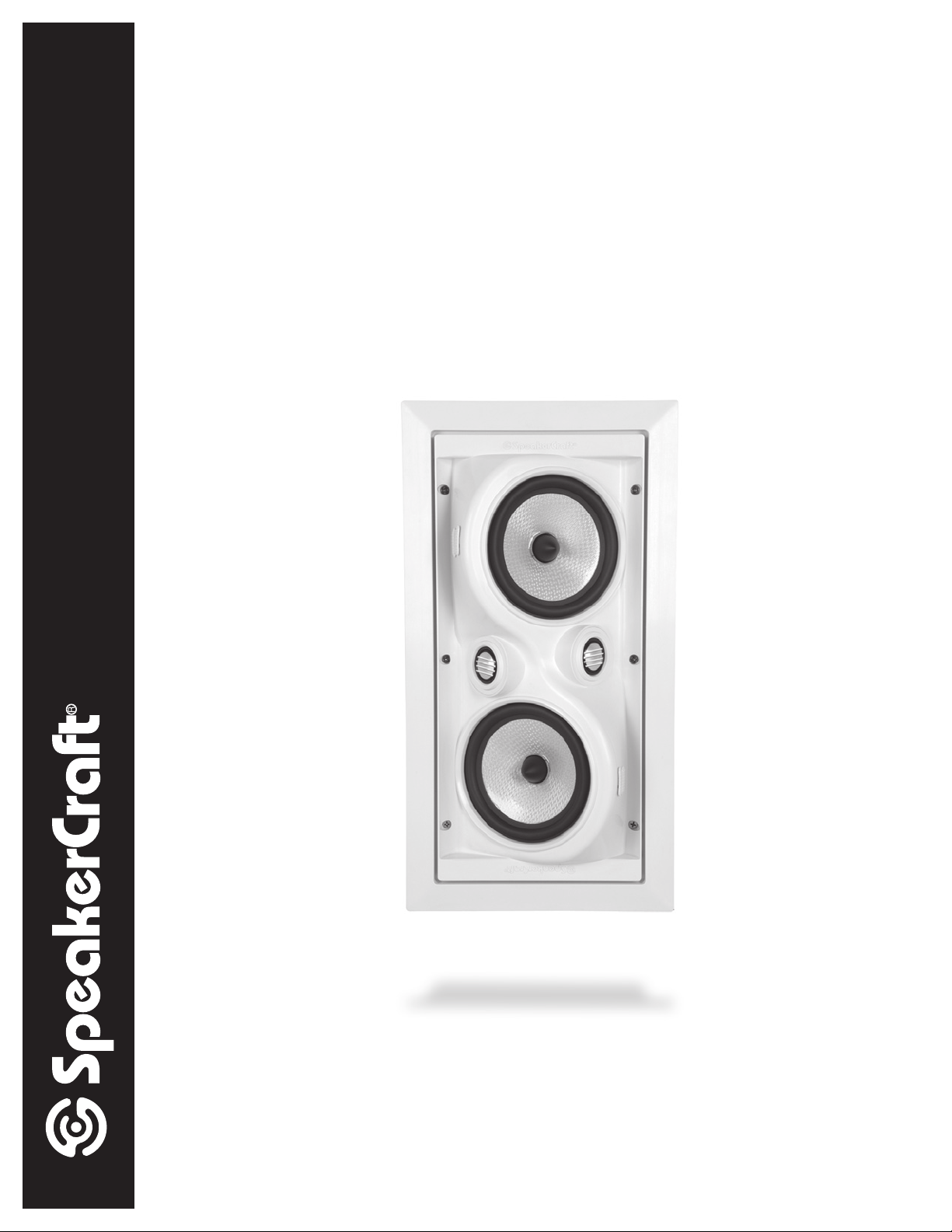
OWNER'S MANUAL
AIM DIPOLE
Surround Home Cinema Speakers
AIM CINEMA DIPOLE FIVE | AIM CINEMA DIPOLE THREE | AIM CINEMA DIPOLE ONE
Page 2
FR
FL
C
RR
RL
LS
RS
INTRODUCTION
Congratulations on purchasing Speakercraft's AIM DIPOLE in-wall speaker. The AIM DIPOLES feature two 5¼ inch drivers and two
1-inch dome tweeters placed 50 degrees off-axis from each other. Two switchable settings allow the speaker to operate in either
a bipole conguration or in opposite polarity as a dipole to create the desired null at the listening area. In the second position
there is a circuit to boost bass response, which would normally be lost in the cancellation through the opposite output from the
two woofers. The drivers are mounted in a bafe that has been carefully molded with graceful curves and angles to avoid any
sharp reections. The result is a piece of acoustic artwork that is impressive in both its style and its performance.
PLACEMENT
SpeakerCraft highly recommends the use of a qualified custom installation specialist when installing your AIM DIPOLE speakers.
If you need assistance in locating a dealer, please contact SpeakerCraft at 1-800-448-0976.
1. Determine Your Primary Listening Area
The area where you will most likely be sitting when listening to your speakers is your primary listening area.
2. Mounting Location
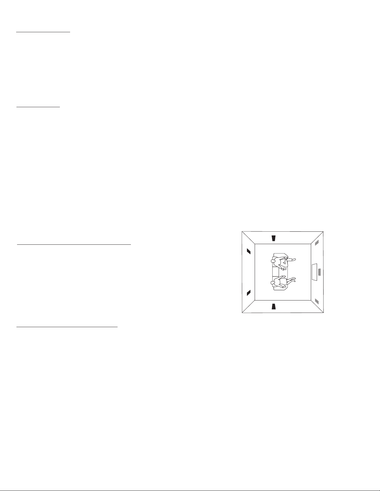
The AIM DIPOLE speakers were designed to be mounted in the side or rear walls of a home theater system, slightly above the
listening position. See Figure 1.
3. Check for Obstructions
Before confirming the placement of your AIM DIPOLE speakers you should carefully consider the location of studs, fire blocks,
electrical, plumbing and other fixtures that may get in the way. If you are installing the speakers into an existing wall, you can
locate obstructions by noting the placement of wall fixtures and if possible gaining access to an attic or crawl space for further
analysis. A good quality stud-finder, found at any building supply store, will help you determine where the studs are located
in the wall.
Figure 1
INSTALLATION CONSIDERATIONS
Prior to the actual installation of the speakers, it will be necessary
to run cables to the speaker location. See your Authorized
SpeakerCraft Dealer for more information on cable installation.
After the cable has been installed, you are ready to mount the
speakers.
INSTALLATION PREPARATION
New Construction
When installing the AIM DIPOLE into a newly built wall, please follow these instructions carefully:
1. Determine Placement
Determine where in the wall the speakers will be placed, using the recommendations under “PLACEMENT”. Pay careful attention
to the section on avoiding obstructions.
2. Mount InstaLLock
For best results, mount the SpeakerCraft InstaLLock
the instructions included with the bracket. See Figure 2.
3. The Location is Ready for Drywall
The bracket provides a stable opening around which the drywall installer can cut out an opening, providing a perfect loca-
tion for installation of the AIM DIPOLE. See Figure 3.
™
Bracket
™
New Construction Bracket (sold separately) for the AIM DIPOLE following
1
Page 3
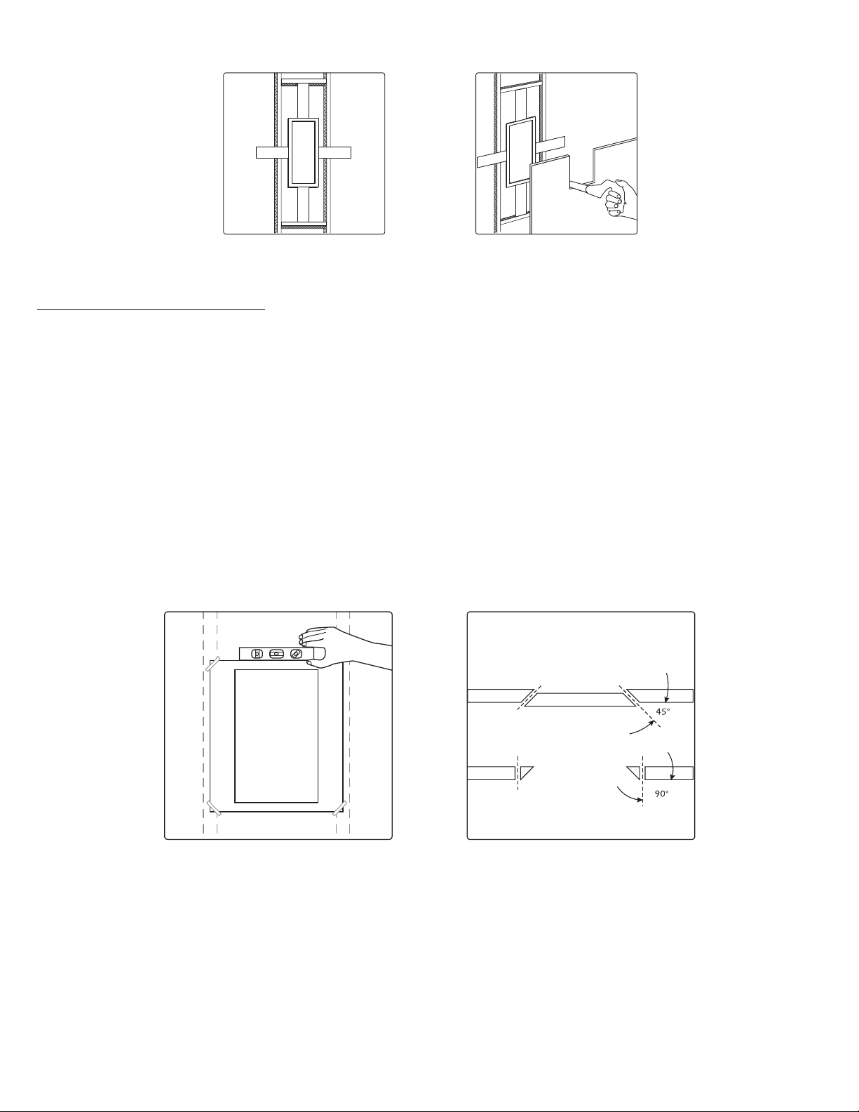
Figure 2
TOP VIEW OF WALL
First Cut
Second Cut
Figure 3
INSTALLATION PREPARATION
FINISHED WALL
When installing the AIM DIPOLE into a finished wall, please follow these instructions carefully:
1. Determine Placement
Determine where in the wall the speakers will be placed, using the recommendations under “PLACEMENT”. Pay careful attention
to the section on avoiding obstructions.
2. Locate Obstructions
Find the studs nearest the desired speaker mounting location. The use of a good stud-finder tool is highly recommended for
this procedure. The speakers should be centered between the two 16" on center studs. Make sure that there are no studs or
obstructions where you plan to install the speaker. Read “Check for Obstructions” under the section “PLACEMENT”.
3. Trace Template
Place the cutout template at the location you have decided to place the speaker. Keep in mind that the flange of the speak-
er baffle will extend beyond the cut opening by
7
⁄8" in most cases. Center the template between the studs. With the template
in place, use a level along the top or bottom edge to make sure it is even with the floor and ceiling. Use a few pieces of tape
or small tacks to hold the template in place. See Figure 4. Trace an outline on the wall with a pencil.
Figure 4 Figure 5
4. Cut the Hole
CAUTION: This is the most important part of the entire installation. If you are not certain whether or not an obstruction exist behind
the desired mounting area, you should start by cutting a small hole in the center of your penciled mounting hole with a drywall
saw. Cut at a 45˚ angle towards the inside of the hole. See Figure 5. Cutting the small hole at this angle will make drywall repair
much easier as the piece cut out can be installed neatly back into the hole. Once you have determined that there aren’t any
obstructions in your desired mounting location, start cutting the finished hole at a 90˚ angle to the wall surface.
2
Page 4
SPEAKER INSTALLATION
FR
FL
C
RR
RL
RED
POLARITY
DOT
LS
RS
RED
POLARITY
DOT
RED
POLARITY
DOT
RED
POLARITY
DOT
The unique integral six foot mounting system incorporated into
each AIM DIPOLE speaker allows for a quick installation by following
these easy steps:
1. Remove the grille.
2. Attach the speaker cable (observing the proper polarity with
your amplifier, + to + and – to –). Make sure the left channel
of the amplifier is connected to the left speaker, and the right
channel is connected to the right speaker.
3. To maintain the correct polarity with your main front speakers,
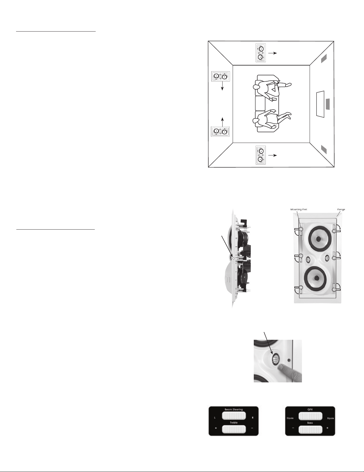
be sure to install the Dipoles with the red polarity dot (Figure 7)
facing towards the direction shown in Figure 6
4. Make sure the mounting feet are turned inward to clear the
opening, and insert the speaker into the wall cut-out. Position
the speaker into the cut-out. NOTE: The flange of the speaker
is designed to flex and conform to any small imperfections in
the wall’s surface. Tighten the six screws on the front of the
baffle only enough to make the flange become snug against
the wall. As you tighten the screws, the feet will automatically
flip into an outward position (Figure 8), thereby clamping the
drywall between the feet and the flange. CAUTION: Over
tightening may warp the baffle, crack the wall, cause flange
to distort, and make the grille difficult to install.
Figure 6
5. Push the grille firmly into the slot in the speaker baffle.
SPEAKER ADJUSTMENTS
Pivoting Tweeter Adjustment
Your AIM DIPOLE Series speakers come from the factory with the
tweeter facing straight out from the baffle. This will result in the
overall smoothest response. However, depending on your particular primary area, room acoustics, ceiling height, or personal
preference, you may find the sound more pleasing by pointing
the tweeters in a particular direction. If additional treble is desired
in the primary listening area, point the tweeter towards that area;
and if less treble is required, point the tweeter away. Push gently
at the edge of the tweeter to point it in the desired direction. See
Figure 9. CAUTION: Avoid touching tweeter dome as damage
WILL occur on metal dome tweeters.
Treble Adjustment: (AIM DIPOLE FIVE AND THREE)
The switch labeled TREBLE allows for 3dB of tweeter adjustment.
Your speakers were shipped with the Treble switch in the ”+” position, providing +3dB of treble. If you want less treble, slide the
switch to the “–” position and the tweeter will play –3dB of treble.
See Figure 10.
Bass Adjustment:
The switch labeled BASS allows for 3dB of bass adjustment. Your
speakers were shipped with the Bass switch in the ”+” position,
providing +3dB of bass and an impedance of 6 ohms. If you want
less bass, slide the switch to the “–” position and the woofer will
play –3dB of bass and increase the impedance to 8 ohms. See
Figure 11.
Remember that altering the impedance affects the number of
speakers able to be driven by an amplifier. If multiple pairs of
speakers are to be driven by one amplifier, SpeakerCraft suggests
using the lowest output position (switch set to the “–” position)
until it is determined that the amplifier will operate properly with
the speakers switched to a higher output mode. If you want to
safely operate multiple pairs of speakers, consider purchasing
SpeakerCraft S4 or S8 Speaker Selectors.
Figure 7
Red
Polarity
Dot
Push Tweeter Here
Figure 8
Figure 9
Figure 10
Figure 11
3
Page 5
Bipole/Dipole/QFX Adjustments (AIM DIPOLE FIVE and AIM DIPOLE THREE)
This three-position switch has the following functions:
Bipole Mode
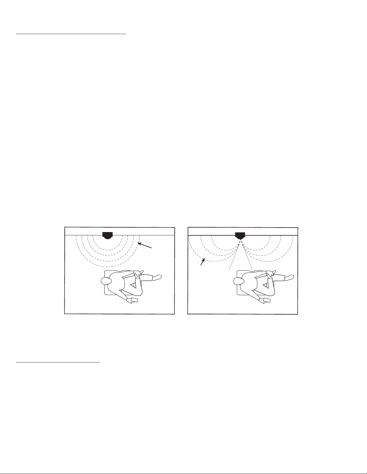
In this mode, all drivers are acoustically in phase, there is no dipole null on the listening axis, so the system creates a broad but
localizable sound stage appropriate for music listening as main speakers. The high and midrange frequency dispersion pattern is
broader than a typical two-way or three-way speaker system. Figure 12 illustrates how the sound is radiated when using in Dipole
mode.
Dipole Mode
In this mode, the relative phase of one tweeter-woofer pair is inverted relative to the other pair. Due to the relative positioning of
the drivers and to the Dipole or 'gure eight' radiation pattern, this creates an output null on the listening axis, and the reproduced
soundstage becomes wider and more diffuse, often creating 'false placement' of reproduced sound cues--sounds seem to come
from apparently distant points of the room instead of the speaker. Figure 13 illustrates how the sound is radiated when using in
Dipole mode.
QFX (Hybrid Dipole/Bipole)
In this mode, the upper frequencies radiate in dipole conguration, while the low frequencies radiate in bipole mode. This setting
adds a diffuse character to the more directional high frequencies that carry most of the directional cues in any type of recorded
signal, while also keeping an omnidirectional bass radiation pattern. This setting may be particularly useful for music listening
where more rear-channel image cohesion is desired than when in full dipole mode.
Beam Steering Adjustments (AIM DIPOLE FIVE only)
This three-position switch function allows the user to AIM to select one of three angles for the main acoustic output lobe--0 degrees
(normal position), 25 degrees frontward, and 25 degrees rearward. The user can select the direction of maximum acoustic output.
This function allows the user to select, for example, the direct/ambient ratio of the output to allow more sound to 'reect' off the
rear wall according to individual listening taste, to 'steer' around a room pillar or some other permanent object, or to otherwise
compensate for a sometimes less that ideal placement requirement of an inwall system.
Figure 12
Wall Wall
Omni Directional
BIPOLE MODE
Figure 13
“Figure Eight”
DIPOLE MODE
Null
Region
PAINTING THE SPEAKERS
If you plan to paint your speakers, we recommend that it be done prior to installation. If you decide to paint your speakers
sometime in the future, it is best to remove them by simply reversing the steps for “SPEAKER INSTALLATION”. When painting the
speakers, the paint masks provided in the carton must be installed in place of the grille. The grilles can also be painted, however,
great care should be taken not to clog the holes, as this will greatly reduce the sound quality of the speakers. Before painting
the grilles, remove the under grille material. Put this material back into place once the grille has been painted. SpeakerCraft
recommends only light spray painting, using 5 parts thinning agent to 1 part paint. Do not paint grilles while they are attached to
the speaker. If it is necessary to paint the under grille material, follow the same procedure used to paint the grilles.
4
Page 6
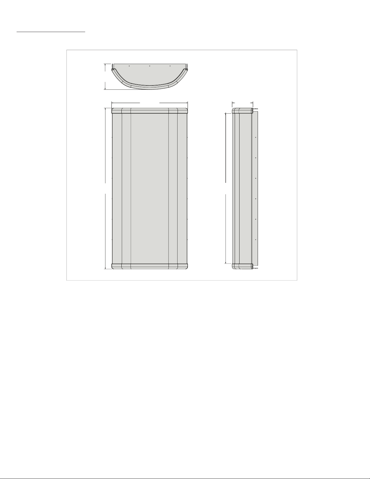
GRILLE DIMENSIONS
2.470”
62.78mm
15.480”
393.300mm
7.330”
186.250mm
14.440”
366.700mm
2.010”
50.980mm
5
Page 7

SPECIFICATIONS
Speaker Type:
Tweeter:
Woofers:
Impedance:
Bipole Efficiency:
Dipole Efficiency:
Frequency Adjustments:
Frequency Response:
Power Handling:
Dimensions (W x H x D):
Cut Out Dimensions (W x H):
AIM CINEMA DIPOLE FIVE
2-Way In-Wall
(2) Pivoting 1" Aluminum
Magnesium Dome
(2) 51⁄4" Kevlar Cone Woofers
with Phasing Cones
8 ohms compatible
91dB 1W/1m
82dB 1W/1m
Front-Mounted Bipole, Dipole,
QFX, Beam Steering, Treble & Bass
Adjustment Switches
48Hz - 20kHz
100 watts
91⁄4" x 177⁄16" x 31⁄4"
(234.950mm x 442.980mm x 82.550mm)
71⁄2" x 155⁄8"
(190.500mm x 397.010mm)
AIM CINEMA DIPOLE THREE
2-Way In-Wall
(2) Pivoting 1" Aluminum Dome
(2) 51⁄4" Aluminum Cone Woofers
with Phasing Cones
8 ohms compatible
90dB 1W/1m
82dB 1W/1m
Front-Mounted Bipole, Dipole, QFX,
Treble & Bass Adjustment Switches
50Hz - 20kHz
100 watts
91⁄4" x 177⁄16" x 31⁄4"
(234.950mm x 442.980mm x 82.550mm)
71⁄2" x 155⁄8"
(190.500mm x 397.010mm)
AIM CINEMA DIPOLE ONE
2-Way In-Wall
(2) Pivoting 1" Silk Dome
(2) 51⁄4" IMG Cone Woofers
with Phasing Cones
8 ohms compatible
89dB 1W/1m
81dB 1W/1m
Front-Mounted Bipole, Dipole, QFX,
Adjustment Switches
55Hz - 20kHz
80 watts
91⁄4" x 177⁄16" x 31⁄4"
(234.950mm x 442.980mm x 82.550mm)
71⁄2" x 155⁄8"
(190.500mm x 397.010mm)
In our attempt to constantly improve our products, features and specifications are subject to change without notice.
Declaration of Conformity
We, Speakercraft Inc.
940 Columbia Ave.
Riverside, CA 92507
USA
declare under our sole responsibility that the products described in
this owners manual are in compliance with technical standards
EN 50081-2 EMC, Emission
EN 50082-2 EMC, Immunity
940 Columbia Ave. Riverside CA 92507
SpeakerCraft Inc.
(800) 448-0976 Fax (951) 787-8747
www.speakercraft.com
6
Page 8

LIMITED LIFETIME WARRANTY
SpeakerCraft Inc. warrants to the original retail purchaser only that this SpeakerCraft product will be free from defects in materials and workmanship, provided the
speaker was purchased from a SpeakerCraft Authorized Dealer.
Defective products must be shipped, together with proof of purchase, prepaid insured to the SpeakerCraft Authorized Dealer from whom they were purchased, or to
the SpeakerCraft factory at the address listed on this installation instruction manual. Freight collect shipments will be refused. It is preferable to ship this product in the
original shipping container to lessen the chance of transit damage. In any case, the risk of loss or damage in transit is to be borne by the purchaser. If, upon examination at the Factory or SpeakerCraft Authorized Dealer, it is determined that the unit was defective in materials or workmanship at any time during this warranty period,
SpeakerCraft or the SpeakerCraft Authorized Dealer will, at its option, repair or replace this product at no additional charge, except as set forth below. If this model
is no longer available and can not be repaired effectively, SpeakerCraft, at its sole option, may replace the unit with a current model of equal or greater value. In
some cases where a new model is substituted, a modification to the mounting surface may be required. If mounting surface modification is required, SpeakerCraft
assumes no responsibility or liability for such modification. All replaced parts and product become the property of SpeakerCraft Inc. Products replaced or repaired
under this Warranty will be returned to the original retail purchaser, within a reasonable time, freight prepaid.
This Warranty does not include service or parts to repair damage caused by accident, disaster, misuse, abuse, negligence, inadequate packing or shipping procedures, commercial use, voltage inputs in excess of the rated maximum of the unit, or service, repair or modification of the product which has not been authorized
or approved by SpeakerCraft. This Warranty also excludes normal cosmetic deterioration caused by environmental conditions. This warranty will be void if the Serial
Number on the product has been removed, tampered with or defaced.
This Warranty is in lieu of all other expressed warranties. If the product is defective in materials or workmanship as warranted above,
the purchaser’s sole remedy shall be repair or replacement as provided above. In no event will SpeakerCraft be liable for any incidental or consequential damages arising out of the use or inability to use the product, even if SpeakerCraft Inc. or a SpeakerCraft
Inc. Authorized Dealer has been advised of the possibility of such damages, or for any claim by any other party. Some states do not
allow the exclusion or limitation of consequential damages, so the above limitation and exclusion may not apply.
All implied warranties on the product are limited to the duration of this expressed Warranty. Some states do not allow limitation on
the length of an implied warranty. If the original retail purchaser resides in such a state, this limitation does not apply.
SpeakerCraft offers a variety of accessories to make your installation of this and other SpeakerCraft products easy, economical, and professional. Contact your
authorized SpeakerCraft Dealer for more information. For technical inquires, please call 1-800-448-0976 or e-mail us at [email protected]. We are available to assist you every weekday, except holidays, between the hours of 7:00 a.m. and 5:00 p.m. PST.
940 Columbia Ave., Riverside CA 92507 | USA (800) 448 0976 Fax (951) 787 8747 International +1 951 787 0543 | www.speakercraft.com
LIT73500(rev3)
 Loading...