

Page 1
Maint ena nce
• Check t hat t he br ack et is secure and sa fe to u se at r egu lar intervals (at l eas t eve ry three months ).
• Pleas e con tac t you r dealer if you hav e any q ues tio ns.
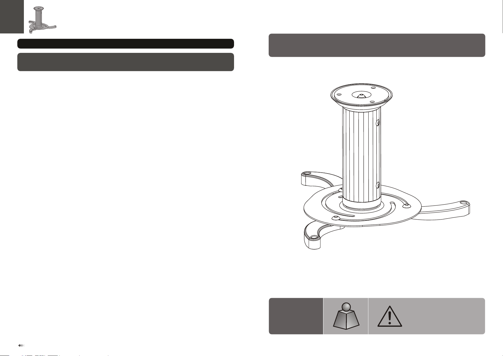
INSTALLATION MANUAL
Projector Ceiling Mount
11
PRB-1
10kg
10kg
(22lbs)
(22lbs)
RATE D
RATE D
CA UTI ON : DO NOT EXCE ED RATED
LIS TED W EIG HT CAPA CIT Y. SE RIOU S
INJURY OR P ROP ERTY DAMA GE MAY
OCC UR!
ISSUED: FEB. 2013
Page 2
NOTE: Rea d the entire instr uction manual be fore you st art ins tallati on and assembly.
WARNING
• Do not begin the installation until you have read and understood the instructions
and warnings contained in this installation sheet. If you have any question
regarding any of the instructions or warnings, please contact your local distributor.
• This mounting bracket was designed to be installed and utilised ONLY as
specified in this manual. Improper installation of this product may cause damage
or serious injury.
• This product should only be installed by someone with good mechanical ability
who has basic building experience and fully understands this manual.
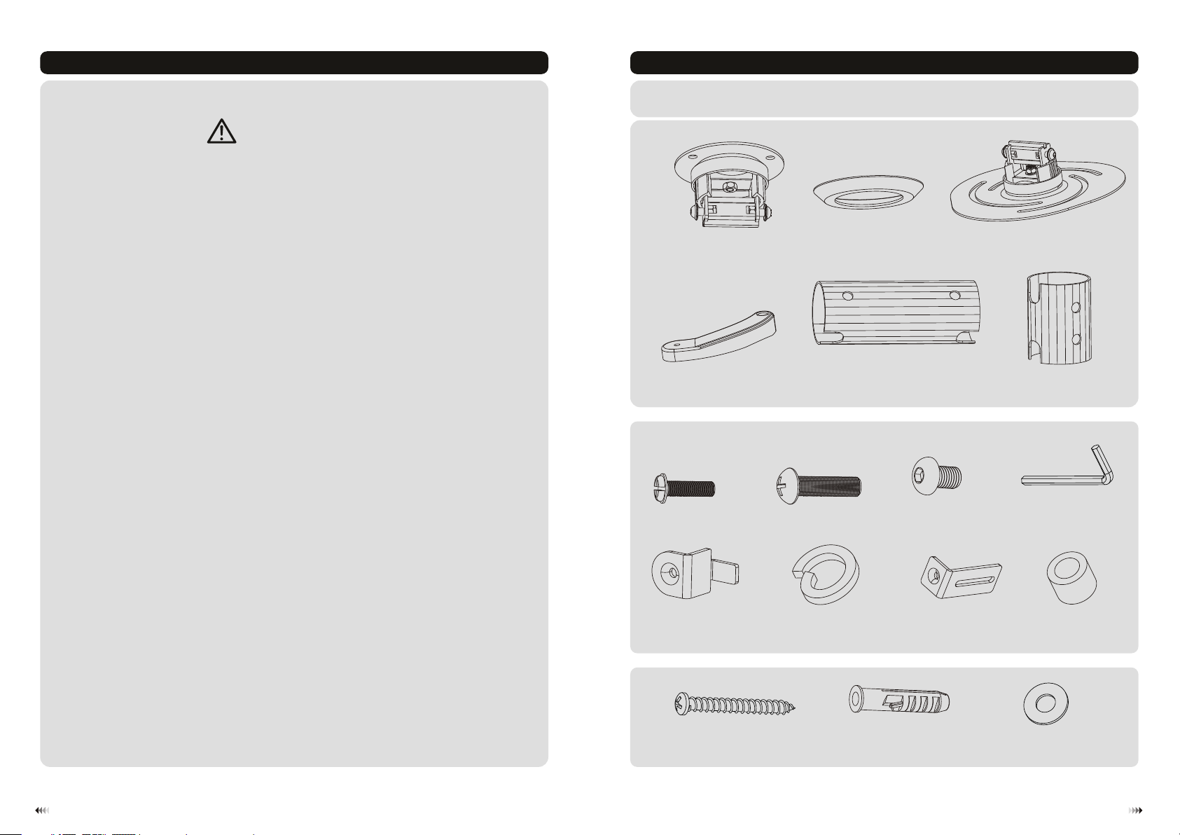
Component Checklist
IMPORTANT: En sure that y ou ha ve re cei ved all par ts ac cor din g to the comp one nt ch eck lis t prior to in sta lla tio n.
If an y par ts ar e mis sing or fau lty, t ele phone you r loc al di str ibutor fo r a rep lac eme nt.
ceiling plate (x1)
A
decorative cover (x1)
B
projector plate (x1)
C
• Make sure that the supporting surface will safely support the combined weight of
the equipment and all attached hardware and components.
• Always use an assistant or mechanical lifting equipment to safely lift and position
the equipment.
• Tighten screws firmly, but do not over tighten. Over tightening can cause damage
to the items, This greatly reduces their holding power.
• This product is intended for indoor use only. Using this product outdoors could
lead to product failure and personal injury.
mounting leg (x3)
Package M
M4x14
(x4) M5x20
M-A
adj usta ble pa rt (x3 )
M-E
Package W
ST6.3 x50 ( x3)
D
W-A
15cm extension pipe (x1)
(x3) 4mm Allen key (x1)
M-B
M6 washer (x3)
M-F
E
M6x 12 (x3 )
M-C
adj usta ble pa rt (x2 )
concr ete a nch or (x 3)
W-B
M-G
8cm extension pipe (x1)
D6 wash er (x 6)
F
M-D
spa cer (x 6)
W-C
M-H
21
Page 3

1a. Wood Ceiling Mounting
55mm
55mm
50mm
(2.2")
2.2"( )
(2")
ø 4.5mm
(ø 3/16")
1b. Solid Brick and Concrete Mounting
55mm
55mm
55mm
(2.2”)
2.2”( )
(2.2")
ø 10mm
(ø 3/8")
1
W-A
W-C
XX
Fin d and ma rk
the e xact l ocat ion
of mo unti ng hol es
2
3
Drill three
pilot holes
Screw the
ceiling plate
onto the ceiling
W-C
W-B
1
Mar k the ex act
loc ation of
mou nting
hol es
2
Drill three pilot
holes
Screw the
ceiling plate
onto the ceiling
WARNING
• Installers are responsible to provide hardware for other types of mounting situations.
• Installers must verify that the supporting surface will safely support the combined weight of the
equipment and all attached hardware and components.
3
W-A
WARNING
Installers must verify that the supporting surface will safely support the combined weight of
the equipment and all attached hardware and components.
4
Page 4

2. Installing the Decorative Cover and the Extension Pipe
3. Attaching the Mounting Legs and the Projector Plate
3a.co mmon mounting
M-B
Run the p roj ect or
cable s thr oug h
the pip e.
Press i n the t wo
bolts a t the s ame
time an d con nec t
exten sio n pip e to
ceili ng pl ate .
Tur n bol t out side
for max imu m
safet y.
E or F
M-B
M-H
or
or
M-B
M-H
M-H
M-D
Locat e the p roj ect or ’s mo unt ing p oin ts.
Screw t he mo unt ing l egs onto the proj ect or.
DO NOT TI GHT EN ALL SCRE WS AT THI S TIME.
65
Page 5

M-C
M-F
W-C
Place t he pr oje cto r plate on the moun tin g leg s, as c lose as to projec tor c ent er of g ravity as possi ble .
Sligh tly a dju st th e arms to fit slots p att ern o n the p rojector plat e. And t hen u se sc rews and washer s
to fix th e pro jec tor p late.
M-D
3b. for Toshiba projectors
3b-1. For Toshib a projectors
M-G
M-A
Locat e the p roj ect or ’s mo unt ing p oin ts.
Screw t he mo unt ing l egs onto the
proje cto r.
DO NOT TI GHT EN ALL SCRE WS
AT THI S TIME.
M-C
M-F
W-C
M-D
M-B
M-H
M-H
Attac h the a dju sta ble part to
the pro jec tor u sin g the screws.
Place t he pr oje cto r plate on the moun tin g
legs, a s clo se as t o pro jector center o f
gravi ty as p oss ibl e. Slightly adj ust t he
arms to f it sl ots p att ern o n the projec tor
plate . And th en us e scr ews and washers
to fix th e pro jec tor p late.
Tig hte n the a ll mounting scr ews w hic h sec ure the mountin g leg s to th e pro jector at this ti me.
7
Tig hte n the a ll mounting scr ews
which s ecu re th e mou nting legs
to the pr oje cto r at th is ti me.
8
Page 6

3b-2. for Philips projectors
M-E
Inser t adj ust abl e part into
proje cto r.
M-B
M-H
M-H
4. Hang the Projector onto the Ceiling Mount
M-D
Locat e the p roj ect or ’s mo unt ing p oin ts.
Screw t he mo unt ing l egs onto the
proje cto r.
DO NOT TI GHT EN ALL SCRE WS
AT THI S TIME.
M-C
M-F
W-C
Tig hte n the a ll mounting scr ews w hic h
secur e the m oun tin g legs to the proje cto r
at this t ime .
M-D
Place t he pr oje cto r plate on the moun tin g
legs, a s clo se as t o pro jector center o f
gravi ty as p oss ibl e. Slightly adj ust t he
arms to f it sl ots p att ern o n the projec tor
plate . And th en us e scr ews and washers
to fix th e pro jec tor p late.
Tur n bol t out side for maximu m
safet y.
Press i n the t wo bo lts a t the s ame time and c onn ect p roj ector plate to pi pe.
Impor tan t: Ma ke su re th e projecto r is co rre ctl y hooked before r ele asi ng th e projector.
5. Adjustment
36 0°
-15° ~ 15°
Adjus t to th e des ire d location or til t.
109
 Loading...