

Page 1
INSTALLATION MANUAL
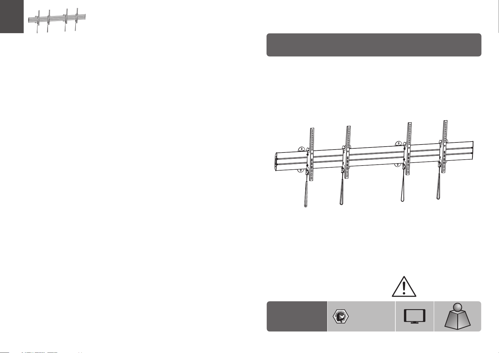
Menu Board Wall Mount
LVW05-246T
200x200/300x300
400x200/400x400
600x400
CAUTION: DO NOT EXCEED
RATED LISTED WEIGHT. SERIOUS
INJURY OR PROPERTY DAMAGE
MAY OCCUR!
55"
MAX
45kgx2
45kgx2
(99lbsx2)
(99lbsx2)
RATED
RATED
ISSUED: MAY. 2014
Page 2
NOT E: Read the entire instruction manual before you start installation and assembly.
WARNING
• Do not begin the installation until you ha ve read and understood all the instructions
and warnings contained in this installation sheet. If you have any ques tions
regarding any of the instructions or warnings, please contact your local distributor.
• This mounting bracket was designed to be installed and utilised ONLY as
specified in this manual. Improper installation of this product may cause damage
or serious injury.
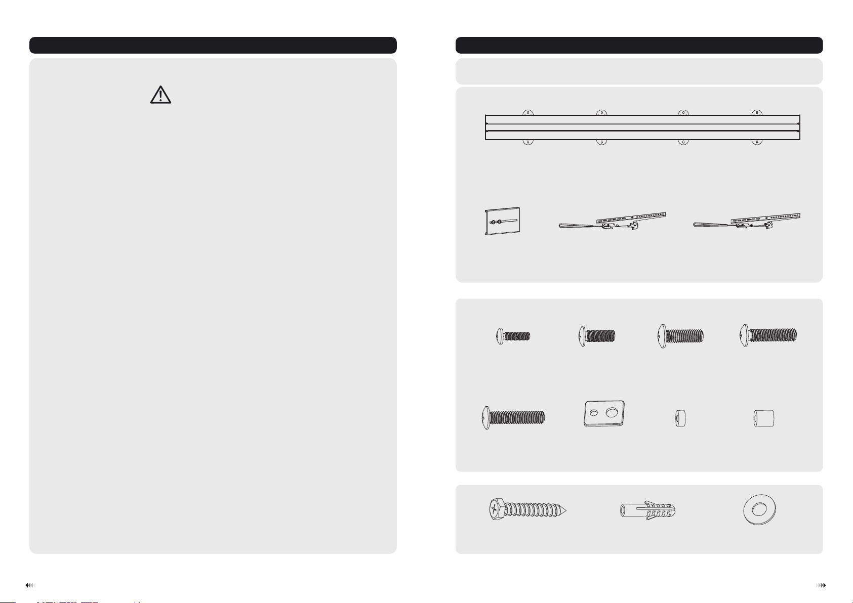
Component Checklist
IMP ORTANT: Ensure that you have received all parts according to the component checklist prior to install ation.
If any parts are missing or faulty, telephone your local distributor for a replacement.
wall plate
(x1)
A
• This product should only be instal led by someone with good mechanical ability
who h as basic building experience and fully understands th is manual.
• Make sure that the supporting surface will safely support the combined weight of
the equipment and all attached hardware and components.
• If mounting to wood wall st ud s, make sure t hat mounting screws are anchored
into the center of the studs. The use of a stud finder is h ig hly recommended.
• Always u se an assistant or mechanical lifting equipment to safely lift an d position
the equipment.
• Tighten screws firmly, but do not over tighten. Over tightening can cause damage
to the items, This greatly re duce s their holding power.
• This product is intended for indoor use only. Using this product outdoors could
lead to product failure an d personal injury.
connecting fitting (x1)
B
Pac kage M (x2)
M5x14 (x4)
M-A
M8x30 (x4)
M-E
Pac kage W
ST6.3x55 (x8)
W-A
left adapter bracket
M6x14 (x4)
C
M-B
washer
(x4)
M-F
concrete anchor (x8)
(x2)
M8x20 (x4)
M-C
small spacer (x8)
M-G
W-B
right adapter bracket D(x2)
M6x30 (x4)
M-D
big spacer (x4)
M-H
D6 washer (x8)
W-C
1
2
Page 3
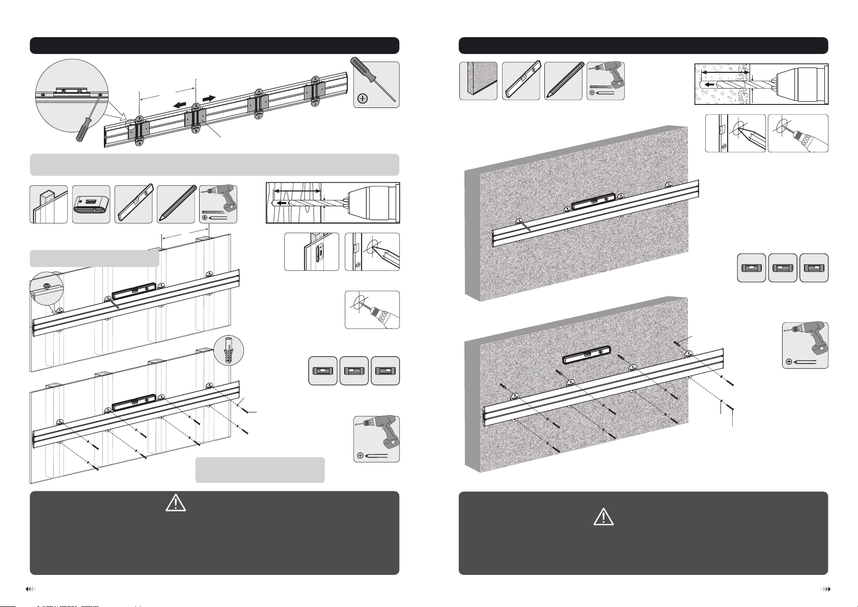
1a. For Wood Stud Wall Mounting
X
1b. For Solid Brick and Concrete Mounting
60mm
60mm
60mm
2.4"()
(2.4")
(2.4")
ø 10mm
(ø 3/8")
base plate
The distance between the baseplates can be adjust ed to fit the distance between the wood studs by using
a screwdriver.
55mm
55mm
55mm
(2.2")
(2.2")
2.2"()
ø 4.5mm
(ø 3/16")
X=406/450/600/610mm
Note: Mount the wall plate with the
screws facing upward.
X
1
Find and mark the exact
location of mounting holes
2
3
Drill pilot holes
XX
√
W-C
W-A
XX
1
Mark the
exact location of
mounting holes
W-B
W-C
W-A
√
2
Drill pilot holes
XX
Screw the wall
plate onto
the wall
Note: If the wall plate fits three wood
studs only, please remove the four th
baseplate us ing a screwdriver.
plate onto the wall
WARNING
• Make sure that mounting screws are anchor ed into the center of th e studs. The use of a stud
finder is highly recommended.
• Installers are responsible to provide hardware for other types of mounting situations.
• Installers must verify that the su pporting surface will safely support the combined weig ht of
the equipment and all at tached hardware and components.
3
Screw the wall
WARNING
Installers must verify that the supporting surface will safely support the combined wei ght of
the equipment and all attached hardware and components.
4
Page 4

2. Installing the Adapter Brackets
2-2. For Bump-out or Recessed Back Screens
2-1 For Flat Back Screens
TV
Top of the display
TV
M-C
M-F
Note: Choose the appropriate screws, washers and spacers (if necessary) according to the type of screen.
M-C/M-D/M-E
ororor
M-G
TV
M-F
M-G
TV
M-D/M-E
M-F
M-H
M-D/M-E
M-F
M-G
M-H
· Position the adapter brackets as close as possible to the center of the disp lay.
TV
TV
M-A/M-B/M-C
· Screw the adapter brackets onto the display.
Tighten all screws but do not over tighten.
3. Hanging the Displays onto the Wall Plate
M-F
65
Page 5
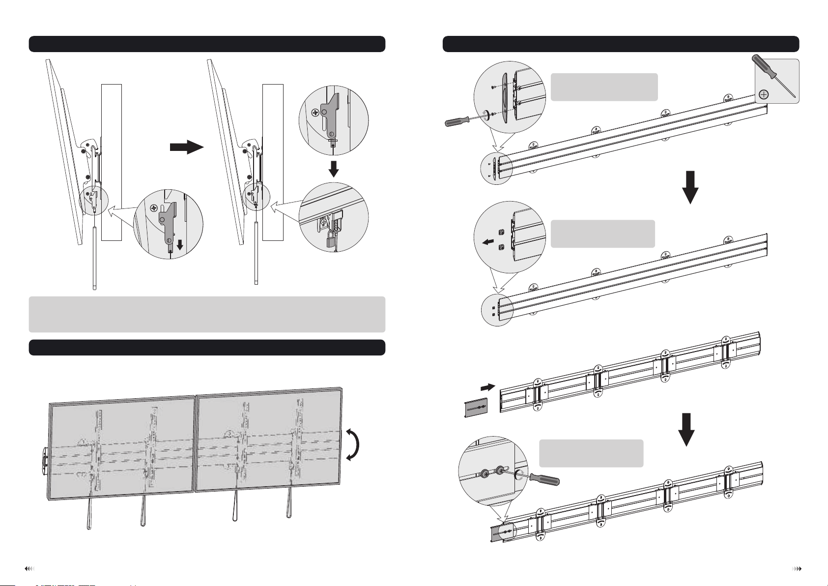
• Lift the display carefully and pull downward t wo straps at the same time , then hook the adapter brackets
to the wall plate.
• Fasten the adapter brackets to the wall plate by releasing the straps.
• Use the padlocks to prevent the di splays from being stolen (The padlocks are not included).
For Multiple Wall Plates Installation
Remove the plastic covers at
one end of wall plates using a
screwdriver.
Remove screws at one end
of the wall plates using a
screwdriver.
4. Adj ustment
7
+5°
-10°
Join the wall plates with the
connecting fitting and tighten
screws to secure them.
8
Page 6

Then skip to step1 for installation.
Maintenance
• Check that the bracket is secure and safe to use at regular interval s(at least every three months).
• Please contact your distributor if you have any questions.
9
10
 Loading...