

Page 1
INSTALLATION MANUAL
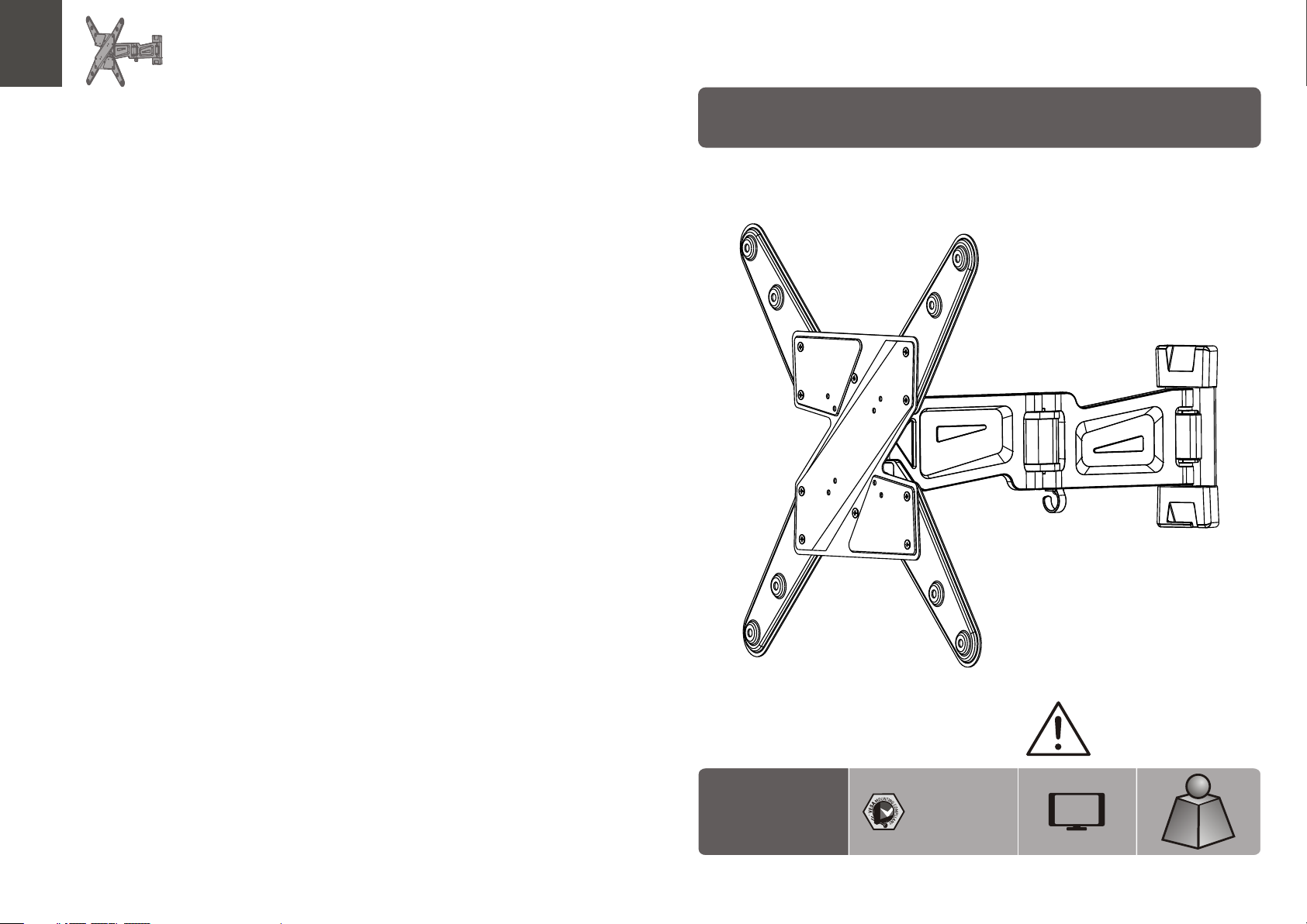
Full Motion LED, LCD TV Wall Mount
LDA10 -44 2
75x75 /10 0x1 00
200x1 00/ 200 x20 0
300x3 00/ 400 x20 0
400x4 00
CA UTI ON : DO NOT EXCE ED
RATE D LIS TED WE IGH T. SERI OUS
INJ URY OR P ROP ERTY DAMA GE
MAY OCCUR!
55"
MAX
(66lb s)
(66lb s)
RATE D
RATE D
ISSUED: JUNE. 2013
30kg
30kg
Page 2
NOTE: Rea d the entire instr uction manual be fore you st art ins tallati on and assembly.
WARNING
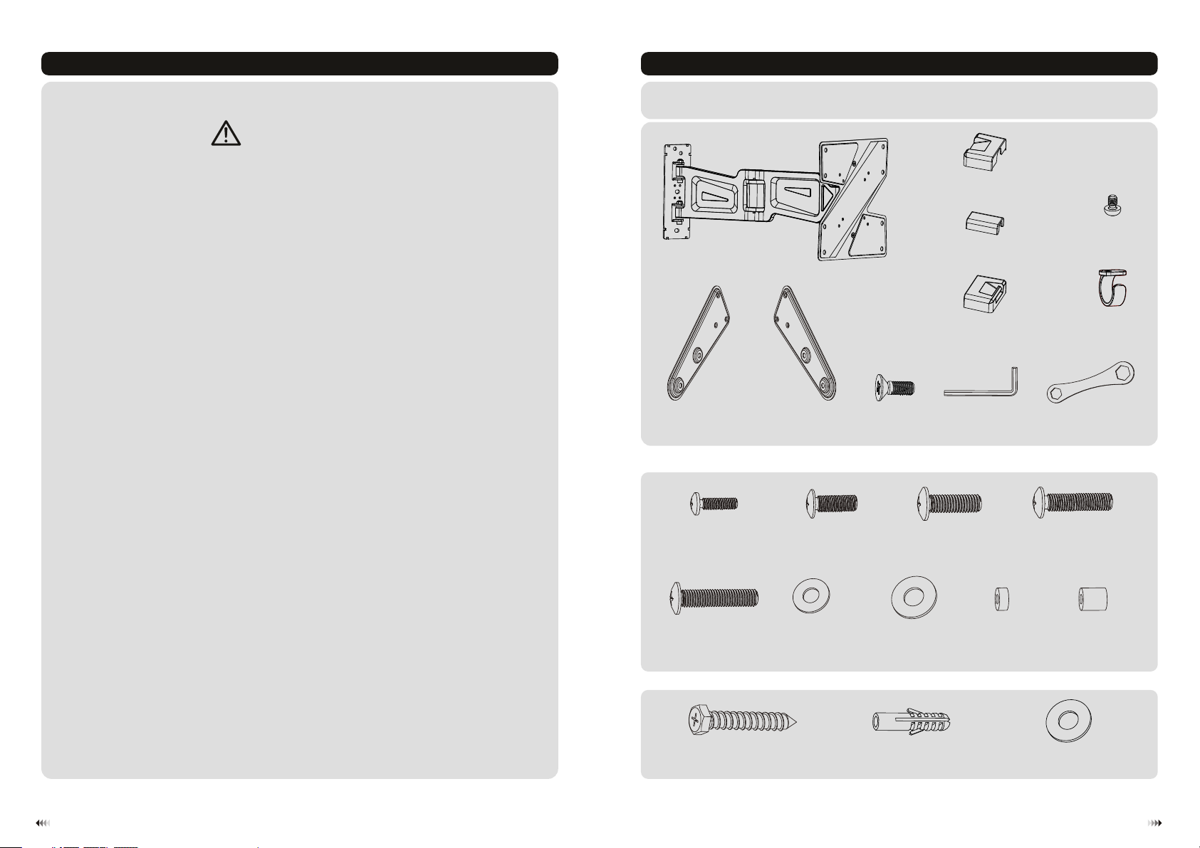
Component Checklist
IMPORTANT: Ensure t hat y ou ha ve re ceived al l par ts ac cor ding to the c omp one nt ch ecklist p rio r to in sta llation.
If an y par ts ar e mis sing or fau lty, t ele phone you r loc al di str ibutor fo r a rep lac eme nt.
• Do not begin the installation until you have read and understood all the instructions
and warnings contained in this installation sheet. If you have any questions
regarding any of the instructions or warnings, please contact your local distributor.
• This mounting bracket was designed to be installed and utilised ONLY as
specified in this manual. Improper installation of this product may cause damage
or serious injury.
• This product should only be installed by someone with good mechanical ability
who has basic building experience and fully understands this manual.
• Make sure that the supporting surface will safely support the combined weight of
the equipment and all attached hardware and components.
• If mounting to wood wall studs, make sure that mounting screws are anchored
into the center of the studs. The use of a stud finder is highly recommended.
• Always use an assistant or mechanical lifting equipment to safely lift and position
the equipment.
• Tighten screws firmly, but do not over tighten. Over tightening can cause damage
to the items, This greatly reduces their holding power.
wall mo unt (x1 )
VESA ada pto r (x )
B
Package M
M5x14 ( x4)
M-A
A
VESA ada pto r (x )C2
2
M6x14 ( x4)
M-B
top dec ora tiv e cov er 1 (x )
middl e dec ora tiv e cover (x1)
botto m (x1)
decor ati ve co ver
M6 (x8)
G
Allen key (x1)
M8x20 ( x4)
M-C
D
M4 (x1)
K
E
cable c lip ( x1)
F
H
wrenc h (x1 )
M6x30 ( x4)
M-D
J
I
• This product is intended for indoor use only. Using this product outdoors could
lead to product failure and personal injury.
M8x30 ( x4)
Package W
M-E
ST6.3 x55 ( x4)
W-A
D (x4)5 washe r
M-F
D8 (x4)washe r
M-G
concr ete a nch or (x 4)
W-B
small s pac er (x 8)
M-H
big spa cer ( x4)
M-I
D6 wash er (x 4)
W-C
21
Page 3

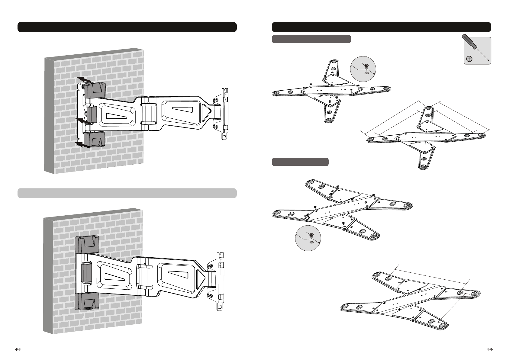
1.Separating the VESA Plate from the Wall Mount
loosen
I
2b. For Solid Brick and Concrete Mounting
60mm
60mm
60mm
(2.4")
2.4"( )
(2.4")
ø 10mm
(ø 3/8")
remov e
2a. For Wood Stud Wall Mounting
W-C
W-A
XX
55mm
55mm
55mm
2.2"( )
(2.2")
(2.2")
Find an d mar k the
exact l oca tio n of
mount ing h ole s
√
ø 4.5mm
(ø 3/16")
1
2
3
Drill pilot holes
X X
W-B
W-C
W-A
Mark th e exa ct
locat ion o f
mount ing h ole s
√
1
2
Drill pilot holes
X X
Screw the wall
mount onto
the wall
Screw the wall
mount onto
the wall
WARNING
• Make sure that mounting screws are anchored into the center of the studs. The use of a stud
finder is highly recommended.
• Installers are responsible to provide hardware for other types of mounting situations.
• Installers must verify that the supporting surface will safely support the combined weight of the
equipment and all attached hardware and components.
3
WARNING
Installers must verify that the supporting surface will safely support the combined weight of
the equipment and all attached hardware and components.
4
Page 4
3. Installing the Decorative Covers
4. Assembling the VESA Adaptors
Insta ll th e dec ora tive covers alo ng th e wal l pla te rail until the y fit s nug ly on to the wall plate .
4a VESA 300x300, 400X400
4b VESA 400x200
Unit: mm
Unit: mm
G
400
40
0
3
0
003
0
G
04
0
2
00
65
Page 5
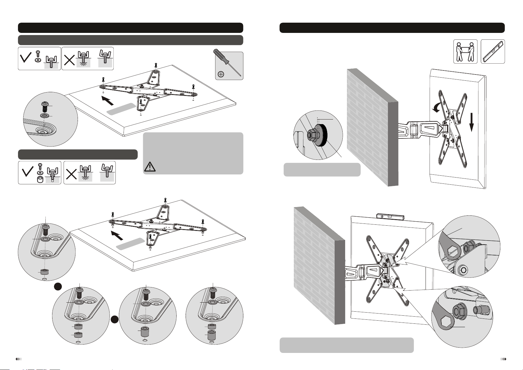
5. Installing the VESA Plate
5-1 For Flat Back Screens
6. Hooking the TV onto the Wall Mount
TV
M-A
B/M- M-C
M-F/M -G
5-2 For Recessed Back Screens
TV
M-C
M-G
TV
TV
TV
ay
displ
he
t
f
o
Top
Note: C hoo se th e app ropriate scre ws,
washe rs an d spa cer s (if necessary ) acc ord ing
to the ty pe of s cre en.
· Posit ion t he VE SA pla te as close as poss ibl e
to the ce nte r of th e dis pla y.
· Screw t he VE SA pla te on to the display.
Tig hten all screws b ut do n ot ov er
TV
tight en.
Loose n or ti ght en th e upper nut
leavi ng a 4m m spa ce to t he fl at nut.
4mm
flat nu t.
I
l
di ay
e sp
th
f
o
op
T
M-H
or
M-G
M-H
M-H
M-C
M-D
M-E
M-G
M-D
M-E
M-G
M-D
M-E
or
M-I
M-H
M-I
I
or
· Level t he TV.
· Place t he lo wer n ut; Ti ghten both nuts .
8877
Page 6

7. Cable Management
Insta ll th e cab le cl ip.
J
K
Connect the cables to your TV and route the cables through the cable clip.
Note: Leave slack in the cable for cantilever arm movement.
8. Adjustment
°
18 0
°+
2
1
2°1
-
°
-3
3
+ °
18 0°
18 °
0
H
It is nec ess ary t o sli ghtly loosen or t igh ten t he ad justment scre ws us ing a n Alle n key according t o the
weigh t of TV install ed.
9
Adjust to the desired position or tilt.
Maint ena nce
• Check t hat t he br ack et is secure and sa fe to u se at r egu lar intervals (at l eas t eve ry three months ).
• Pleas e con tac t you r distributor i f you h ave a ny qu estions.
10
 Loading...