

Page 1
INSTALLATION MANUAL
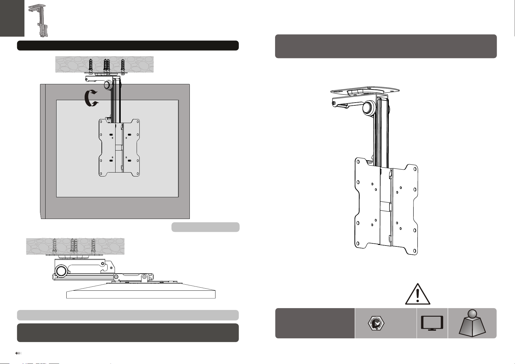
7. Adjustment
0°/- 90 °
Folding LCD Ceiling Mount
Adjus t to th e des ire d position.
For sav ing t he sp ace , you can fold the di spl ay by p ush ing the display b ack u nti l it fi ts in place.
Maint ena nce
• Check t hat t he br ack et is secure and sa fe to u se at r egu lar intervals (at l eas t eve ry three months ).
• Pleas e con tac t you r distributor i f you h ave a ny qu estions.
11
LC D-CM 222
75x75
100x1 00
200x1 00
200x2 00
CAUT ION: DO NOT EXCEED
RATED LIS TED W EIGH T. SERI OUS
INJURY OR P ROP ERTY DAMA GE
MAY OCCUR!
37"
MAX
20kg
20kg
(44lbs)
(44lbs)
RATE D
RATE D
ISSUED: MAY. 2013
Page 2
NOTE: Rea d the entire instr uction manual be fore you st art ins tallati on and assembly.
WARNING
• Do not begin the installation until you have read and understood all the instructions
and warnings contained in this installation sheet. If you have any questions
regarding any of the instructions or warnings, please contact your local distributor.
• This mounting bracket was designed to be installed and utilised ONLY as
specified in this manual. Improper installation of this product may cause damage
or serious injury.
• This product should only be installed by someone with good mechanical ability
who has basic building experience and fully understands this manual.
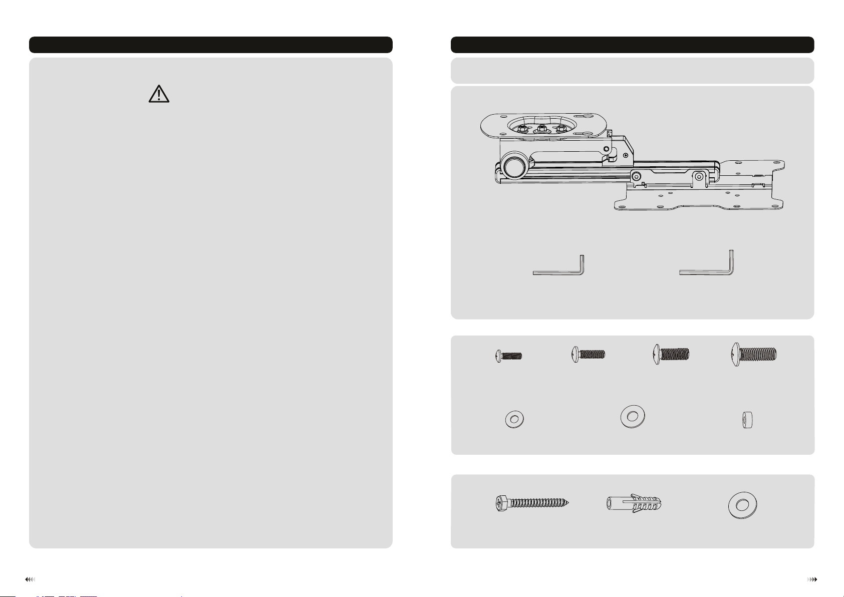
Component Checklist
IMPORTANT: En sur e tha t you have re cei ved a ll pa rts accor din g to th e com ponent ch eck lis t pri or to insta lla tio n.
If an y par ts ar e mis sing or fau lty, t ele phone you r loc al di str ibutor fo r a rep lac eme nt.
ceiling mount (x1)
A
• Make sure that the supporting surface will safely support the combined weight of
the equipment and all attached hardware and components.
• Always use an assistant or mechanical lifting equipment to safely lift and position
the equipment.
• Tighten screws firmly, but do not over tighten. Over tightening can cause damage
to the items, This greatly reduces their holding power.
• This product is intended for indoor use only. Using this product outdoors could
lead to product failure and personal injury.
Package M
M4x14 ( x4)
D5 wash er (x 4)
Package W
4mm Allen key (x1)
M-A
M-E
ST6.3 x55 ( x4)
W-A
B
M5x14 ( x4)
M-B
D8 wash er (x 4)
M-F
concr ete a nch or (x 4)
W-B
6mm Allen key (x1)
M6x14 ( x4)
M-C
C
M8x20 ( x4)
small s pac er (x 8)
D6 wash er (x 2)
W-C
M-D
M-G
21
Page 3

1. Separating the VESA Plate
Loose n
B
Use a pro per Al len k ey to l oosen the screw s in or der t o sep arate the VESA pla te fr om th e cei ling mount.
2. Opening the Mount
3a. For Wooden Ceiling Mounting
55mm
55mm
55mm
(2.2")
2.2"( )
(2.2”)
ø 4.5mm
(ø 3/16”)
1
mar k the ex act
mou nting holes.
2
Drill pilot holes
loc ation of
Press
Screw the screws
into the ceiling
Tig hte n the s crew leaving a
4mm spa ce to c eil ing .
W-A
3
4
Page 4

Align the both holes of ceiling plate to the
screws in ceiling and move the ceiling
plate until the both screws are seated in
upper area of tear-drop mounting holes.
W-C
3b. For Solid Brick and Concrete Mounting
60mm
60mm
60mm
(2.4")
2.4"( )
(2.4")
ø 10mm
(ø 3/8")
1
Mar k the ex act
loc ation of
mou nting holes
2
W-A
Fix the c eil ing p lat e using the two oth er sc rew s and t hen tighten all s cre ws.
WARNING
• Installers are responsible to provide hardware for other types of mounting situations.
• Installers must verify that the supporting surface will safely support the combined weight of the
equipment and all attached hardware and components.
Tig hte n the s crew leaving a
4mm spa ce to c eil ing .
W-B
W-A
Drill pilot holes
Screw the screws
into the ceiling
65
Page 5

Align the both holes of ceiling plate to the
screws in ceiling and move the ceiling
plate until the both screws are seated in
upper area of tear-drop mounting holes.
4. Installing the VESA Plate
Top of the di spl ay
W-C
W-A
Fix the c eil ing p lat e using the two oth er sc rew s and t hen tighten all s cre ws.
WARNING
TV
TV
TV
TV
M-E
M-F
M-A
M-B
M-C
M-D
or
M-G
M-F
M-D
M-G
M-G
M-F
M-D
Installers must verify that the supporting surface will safely support the combined weight of
the equipment and all attached hardware and components.
Not e: Choose the app ropr iate screws, wa sher s and spacers (if n eces sary) accordi ng to th e type of screen.
• Scre w the VES A pla te onto the disp lay.
Tig hten all screws b ut do n ot ov er ti ghten.
87
Page 6

5. Hooking the Display onto the Ceiling Mount
6. Adjustment
Remov e the d eco rat ive
cover s for a dju sti ng
tensi on.
C
Hang th e dis pla y with the VESA
plate o nto t he ce iling mount.
Heigh t
adjus table
It is nec ess ary t hat s lig htly
loose n or ti ght en ad justment
screw s to ad jus t ten sion
using a p rop er All en ke y.
B
B
Insta ll th e scr ews t o fix the ceiling m oun t
and VES A plat e tog eth er tightly.
Loose n scr ews (bu t not remove) and a dju st th e dis play to desired h eig ht as n eed ed, then tighte n scr ews .
109
 Loading...