

Page 1
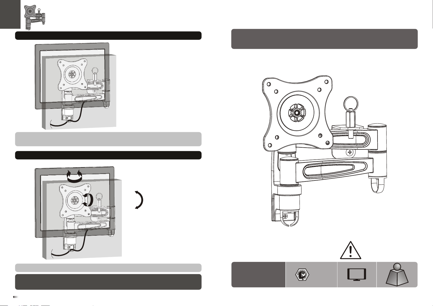
5. Cable Management
Connect cables to your TV and route through the cable clips.
Note: L eav e sla ck in t he cables for can til eve r arm m ovement.
6. Adjustment
INSTALLATION MANUAL
LCD Wall Mount
18 0°
+15°
360°360°360°
-15°
Adjust to the desired location or tilt.
Maint ena nce
• Check t hat t he br ack et is secure and sa fe to u se at r egu lar intervals (at l eas t eve ry three months ).
• Pleas e con tac t you r distributor i f you h ave a ny qu estions.
7
LC D -141 L
75x75
100x1 00
CA UT ION: DO N OT EXCEED
RATE D LIS TED WE IGH T. SERI OUS
INJ URY OR P ROP ERTY DAMA GE
MAY OCCUR!
27"
MAX
(33lbs)
(33lbs)
RATE D
RATE D
ISSUED: JUL. 2013
15kg
15kg
Page 2
NOTE: Rea d the entire instr uction manual be fore you st art ins tallati on and assembly.
WARNING
• Do not begin the installation until you have read and understood all the instructions
and warnings contained in this installation sheet. If you have any questions
regarding any of the instructions or warnings, please contact your local distributor.
• This mounting bracket was designed to be installed and utilised ONLY as
specified in this manual. Improper installation of this product may cause damage
or serious injury.
• This product should only be installed by someone with good mechanical ability
who has basic building experience and fully understands this manual.
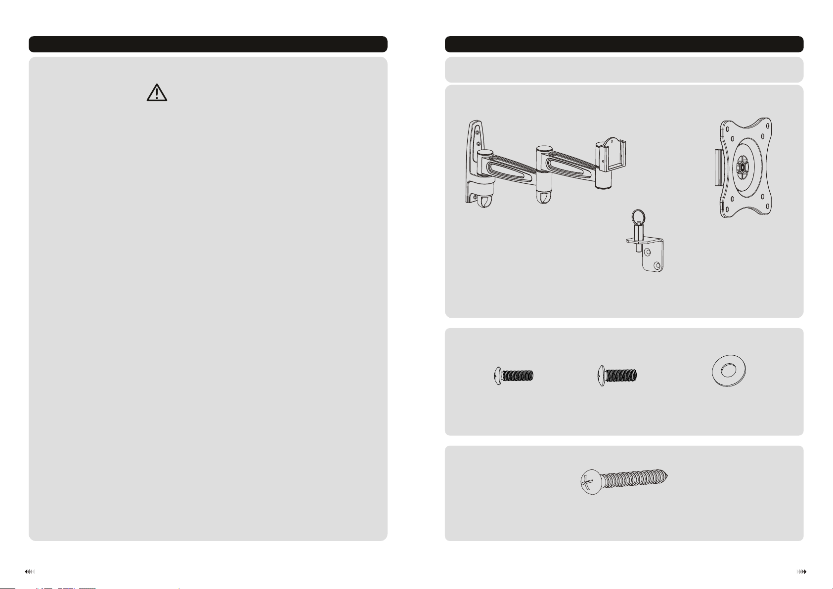
Component Checklist
IMPORTANT: En sur e that you ha ve re cei ved a ll parts ac cor din g to th e compone nt ch eck lis t prior to in sta lla tio n.
If an y par ts ar e mis sing or fau lty, t ele phone you r loc al di str ibutor fo r a rep lac eme nt.
artic ula ted a rm
assem bly ( x1)
A
VESA pla te (x 1)
B
• Make sure that the supporting surface will safely support the combined weight of
the equipment and all attached hardware and components.
• Always use an assistant or mechanical lifting equipment to safely lift and position
the equipment.
• Tighten screws firmly, but do not over tighten. Over tightening can cause damage
to the items, This greatly reduces their holding power.
• This product is intended for indoor use only. Using this product outdoors could
lead to product failure and personal injury.
Package M
Package W
M4x14 ( x4)
M-A
lock as sem bly ( x1)
C
M5x14 ( x4)
M-B
ST5.5 x50 ( x5)
W-A
D (x4)5 washe r
M-C
21
Page 3

1. Mounting on Wood Walls
55mm
55mm
50mm
(2.2")
2.2"( )
(2”)
ø 4mm
(ø 5/32”)
2. Installing the Lock Assembly
plug
1
loosen
W-A
Find and mark the
exact location of
2
Drill pilot holes
√
mounting holes
X X
Screw the wall
mount onto
the wall
Remove the plug.
Position the lock plate.
lock plate
Fold the articulated arms to make the
arms parallel with the wall.
Unfold the articulated arms and use the lock
plate to mark the two mounting holes.
WARNING
• Installers are responsible to provide hardware for other types of mounting situations.
• Installers must verify that the supporting surface will safely support the combined weight of
the equipment and all attached hardware and components.
3
W-A
Fix the lock plate to the wall using two of the screws.
4
Page 4

2. Install VESA Plate
tight en
Fold the articulated arms to make the arms parallel with the wall again. Tighten the plug into the lock plate to
avoid the arms-shaking when driving.
3. Installing the VESA Plate
4. Hanging the TV onto the Wall Plate
LOCK
TV
Screw t he VE SA pla te on to the TV.
Tig hten all screws b ut do n ot ov er ti ghten.
TVTV
• Slowly fit the VESA plate onto wall plate rail.
• Tighten both set screws to secure it.
Top of the TV
M-C
M
-
A
M B-
Use the padlock to prevent the TV from being stolen. ( Padlock is not included )
5
6
 Loading...