

Page 1
SPEA MEDIA XTC
Hardware User Manual
Hardware-Benutzerhandbuch
Teilenummer 1740 9040.1
Rel. 0895
Copyright by SPEA Software AG
Page 2

Table of Contents
PART 1 INTRODUCTION ........................................................................................................................5
What is the SPEA MEDIA XTC? ..............................................................................................................5
SPEA MEDIA XTC Features ....................................................................................................................6
Included Software .....................................................................................................................................6
SPEA MEDIA XTC Technology ................................................................................................................6
About this Manual .....................................................................................................................................7
README File............................................................................................................................................7
Warranty ...................................................................................................................................................7
Customer Support.....................................................................................................................................7
PART 2 INSTALLING THE SPEA MEDIA XTC.......................................................................................8
What You Need.....................................................................................................................................8
What You Should Have.........................................................................................................................8
Preparing Your Computer.........................................................................................................................8
Installation via a Plug & Play System or Utility (ICU) ................................................................................9
Configuration of the I /O Addresses, Interrupts and DMA Channels ....................................................9
Configuring Your SPEA MEDIA XTC Card............................................................................................... 9
Jumper Locations and Functions ........................................................................................................10
External Audio Connectors .....................................................................................................................11
Internal Audio Connectors ......................................................................................................................11
Installing the SPEA MEDIA XTC Card....................................................................................................12
Software Installation................................................................................................................................13
Software Installation Procedure for DOS / Windows 3.1xx.................................................................13
Standard Modifications........................................................................................................................14
Tips for Successful Installation............................................................................................................14
PART 3 CONFIGURING THE SPEA MEDIA XTC................................................................................15
Configuring Your SPEA MEDIA XTC Card under DOS..........................................................................15
Using SSInit.........................................................................................................................................16
Hardware Configuration Interface (SSINIT) ........................................................................................16
Quick Setup Screen ............................................................................................................................17
Using Advanced Settings ....................................................................................................................17
Hardware Settings Screen ..................................................................................................................18
Hardware Test Screen ........................................................................................................................19
IRQ and DMA Test Screens................................................................................................................19
Mixer Settings Screen .........................................................................................................................19
Exit Screen ..........................................................................................................................................20
MT32 Patch-change Utility ..................................................................................................................21
SPEA MEDIA XTC Digital Audio/MIDI Test Utility...............................................................................21
S2KStat Diagnostic Utility....................................................................................................................21
Using the Intel ISA Configuration Utility (ICU).....................................................................................23
Configuring Your SPEA MEDIA XTC Card under Windows ...................................................................24
The Advanced Settings Display ..........................................................................................................25
PART 4 CONFIGURATION OF THE SPEA MEDIA XTC UNDER WINDOWS® 95 .............................26
Installing the SPEA MEDIA XTC in a Windows® 95 System .................................................................26
Using the SPEA MEDIA XTC with DOS games .....................................................................................26
Using the Mixer.......................................................................................................................................28
Locking Configurations under Windows® 95..........................................................................................29
The Multimedia Properties page .........................................................................................................29
Uninstalling the SPEA MEDIA XTC Software......................................................................................... 29
SPEA MEDIA XTC devices ....................................................................................................................30
Troubleshooting ......................................................................................................................................30
Using DOS Utilities Under Windows® 95 ...............................................................................................30
2
Page 3

PART 5—USING SPEA MEDIA XTC.....................................................................................................31
Using SPEA MEDIA XTC under DOS ....................................................................................................31
Using SPEA MEDIA XTC with Games................................................................................................31
Music Options......................................................................................................................................31
Digital Audio Options...........................................................................................................................31
Using the SPEA MEDIA XTC with Windows ..........................................................................................31
Multimedia Applications.......................................................................................................................31
MIDI Devices under Windows .............................................................................................................31
Using the External MIDI Connector ........................................................................................................32
Using the MIDI Mapper with the SPEA MEDIA XTC ..............................................................................33
Setups .................................................................................................................................................33
Routing MIDI Data to the External MIDI Out Port................................................................................34
Patch Maps .........................................................................................................................................35
Key Maps ............................................................................................................................................35
APPENDIX A ABOUT MIDI....................................................................................................................36
What is MIDI? .........................................................................................................................................36
General MIDI...........................................................................................................................................36
SPEA MEDIA XTC General MIDI Sound Set and MT-32 Sound Set .....................................................36
APPENDIX B TROUBLESHOOTING ....................................................................................................43
Problems when Using Two Sound Cards ...............................................................................................43
Configuration Problems ..........................................................................................................................43
Audio Problems.......................................................................................................................................43
Problems Internal to the SPEA MEDIA XTC ..........................................................................................43
Problems with Games.............................................................................................................................44
Problems under Windows.......................................................................................................................44
Problems with MIDI under Windows .......................................................................................................45
APPENDIX C TECHNICAL SPECIFICATIONS .....................................................................................46
APPENDIX D MIDISOFT RECORDING SESSION PLUS .....................................................................48
APPENDIX E GLOSSARY .....................................................................................................................49
3
Page 4

FCC Radio Frequency
Interference Statement
This equipment has been tested and found to comply with the limits for a Class "B" digital device,
pursuant to part 15 of the FCC rules. These limits are designed to provide reasonable protection
against harmful interference in a residential installation. This equipment generates, uses and can
radiate frequency energy and, if not installed and used in accordance with the instructions, may cause
harmful interference to radio communications. However, there is no guarantee that interference will not
occur in a particular installation. If this equipment does cause harmful interference to radio or television
reception, which can be determined by turning the equipment off and on, the user is encouraged to try
to correct the interference by one or more of the following measures:
Reorient or relocate the receiving antenna.
Increase the separation between the equip-ment and receiver.
Connect the equipment into an outlet on a circuit different from that to which the receiver is
connected.
Consult the dealer or an experienced radio/TV technician for help.
This equipment has been certified to comply with the limits for a Class "B" device, pursuant to Subpart
B of the FCC Rules, it should be used only with equipment certified to comply with the Class "B" limits.
Operation with non-certified equipment is likely to result in inter-ference to radio and television
reception.
This device complies with Part 15 of the FCC Rules. Operation is subject to the following two
conditions:
1. This device may not cause harmful interference, and
2. This device must accept any interference received, including interference that may cause
undesired operation.
Changes or modifications not expressly approved by the grantee of this device could void the user’s
authority to operate the equipment.
Trademarks
SPEA MEDIA XTC is a trademark of SPEA V7.
Windows is a trademark of Microsoft Corporation.
All other trademarks within this manual are the property of their respective companies and are hereby
acknowledged.
4
Page 5

Part 1
Introduction
Congratulations on your purchase of the SPEA
MEDIA XTC card! The SPEA MEDIA XTC
provides the very latest in sound card
technology, offering unparalleled sonic quality
far exceeding that of previous sound cards,
along with powerful facilities for the recording,
playback, and synthesis of sound. The SPEA
MEDIA XTC comes bundled with a selection of
software programs designed to help you get
the most out of its extensive capabilities. With
the SPEA MEDIA XTC, you can add stunning
sound to games, multimedia presentations,
musical compositions, or any other applications
that use sound.
What is the SPEA MEDIA XTC?
The SPEA MEDIA XTC is an expansion card
which adds extensive sound recording and
playback capabilities to your PC, as well as
providing an interface for many popular CDROM drives. Its embedded microprocessor
utilizes custom synthesis technology developed
by ENSONIQ, one of the leading
manufacturers of professional synthesizers and
samplers.
When used with Windows applications, the
SPEA MEDIA XTC meets or exceeds all MPC
(Multimedia PC) Level-3 requirements. When
used with DOS applications, the SPEA MEDIA
XTC offers two operational modes so as to
provide the maximum level of compatibility with
games and other software products currently
on the market. These two modes are:
General MIDI mode
In this mode, the SPEA MEDIA XTC provides
an MPU-401 compatible General MIDI
synthesizer, along with Sound Blaster
compatible digital audio (For more information
about MIDI and General MIDI, see
Appendix A).
MT-32 mode
In this mode, the SPEA MEDIA XTC offers
emulation of the popular Roland MT-32
synthesizer, along with Sound Blaster
compatible digital audio.
5
Page 6

SPEA MEDIA XTC Features
Included Software
Here’s a brief overview of the many features
provided by the SPEA MEDIA XTC:
Plug & Play
The SPEA MEDIA XTC can be installed
without setting jumpers. The configuration of
the boards is done by the software drivers
exclusively. If you use an operating system that
supports Plug & Play, the configuration will be
done automatically.
Synthesizer
Provides up to 32 voices of wavetable
synthesis.
On-board sound ROMs contain 1 megabyte
of sound samples.
Includes General MIDI and Roland MT-32
sound sets as well as AdLib / Sound Blaster
FM synthesizer emulation.
Digital Audio
Allows the recording of CD-quality stereo
sound (up to 16 bits, 44.1 kHz sampling
rate) from Mic/Line, CD/Aux, TV Tuner
and Modem inputs as well as from the
internal synthesizer.
Enables playback of standard PC Wave
files (e.g., .VOC, .WAV, ...).
The SPEA MEDIA XTC comes supplied with
installation software, configuration and
initialization utilities, device drivers, and a
number of applications for both DOS and
Windows. See the software applications
manual included with this package for details
on the DOS and Windows applications.
SPEA MEDIA XTC Technology
The technology from ENSONIQ Corp. which is
used in this board is a combination of hardware
and software that provides the highest quality
in PC sound and the greatest compatibility with
current standards. SPEA MEDIA XTC's driver
compatibility enables continued software
support as new standards emerge.
MIDI
Provides an MPU-401 compatible MIDI
interface, including MIDI In and MIDI
Out/Thru.
Adds an external MIDI In/Out port to your
PC.
Allows the recording of MIDI events from an
external MIDI keyboard controller.
Enables playback of standard PC MIDI files
(e.g., .MID, .ROL, ...) to either the on-board
synthesizer or to an external synthesizer.
Mixer
Provided software mixer allows synthesizer and
digital audio output to be mixed with signal
arriving at the card’s 'CD/Aux', 'TV', 'Modem'
and 'Mic/Line' inputs.
6
Page 7

7
About this Manual
Warranty
We recognize that many people do not read
manuals; however, an ounce of caution is
worth a pound of prevention, so we do strongly
recommend that you take a few moments to go
through these pages before installing your
SPEA MEDIA XTC hardware and software. In
particular, we recommend that you carefully
read the information preceded by the following
two words, which have these special
meanings:
Warning!
This is a warning. It lets you know that if you
fail to heed the accompanying message, you
could damage your system or software. Be
sure to read these!
Note:
This is a hint, tip, or other piece of valuable
information that can save you valuable time
and energy, especially during initial installation.
README File
Our software is constantly being improved and
updated. This means that it may not have been
possible to document the most current
changes in this manual. The latest information
is contained in a file named README on the
diskette coming with your SPEA MEDIA XTC.
You have a 3 year warranty for your SPEA
MEDIA XTC card and 1/2 year warranty for the
corresponding software. To ensure your
warranty, it is necessary that you keep the
invoice of the sound card. If your sound card is
damaged, contact your local retailer first.
Customer Support
If you have problems when installing or using
your SPEA MEDIA XTC card, you can contact
the SPEA V7 Bulletin Board.
Read more about the contents and how to use
this service in Appendix D Service and
Technical Assistance.
Page 8

Part 2
Installing the SPEA
MEDIA XTC
What You Need
To use the SPEA MEDIA XTC, your computer
system should meet the following
requirements:
20MHz 80386 processor or better
VGA or SVGA graphics adapter and
monitor
Mouse
DOS 6.0 or higher
Windows 3.1x or higher or Windows® 95
One open expansion slot
At least 5 Mb of free hard disk space (to
install all software)
What You Should Have
Check to see that your SPEA MEDIA XTC
package contains all of the following items:
SPEA MEDIA XTC sound card in antistatic
bag
SPEA MEDIA XTC hardware manual (this
manual)
SPEA MEDIA XTC software manual
Warranty/registration card
3 1/2" floppy disks or CD ROM
Preparing Your Computer
Warning!
Static electricity can damage your equipment,
but can be easily avoided. Before installing any
internal optional equipment such as the SPEA
MEDIA XTC card, make sure that your
computer system is turned OFF and that you
observe the following antistatic precautions:
Make sure that the AC cable is securely
connected to the computer and is plugged into
a surge protector or grounded AC wall outlet.
(If you are using a surge protector, be sure to
plug it into a grounded AC wall outlet.) Don’t try
to use a two-pronged electrical outlet or
attempt to defeat the power cord’s electrical
ground!
Warning!
Always consult your system manual before
opening your computer to avoid any damage.
1. Switch off your computer and all external
options (printer, display, and others). Be
sure to leave the computer’s power cord
connected to a grounded surge protector or
AC outlet with the computer’s power OFF!
Follow the anti-electrostatic discharge
procedure described on the preceding
pages.
2. If it is necessary to disconnect peripheral
equipment cables from the back of the
computer, be sure to note cable positions
for proper reconnection later.
3. Remove the cover from your computer.
Save the mounting screws for reinstalling
the cover.
8
Page 9

Installation via a Plug & Play
System or Utility (ICU)
Configuring Your SPEA MEDIA
XTC Card
Configuration of the I /O Addresses,
Interrupts and DMA Channels
Under Windows® 95 the configuration of the
SPEA MEDIA XTC will be done automatically,
see also Part 4 in this manual.
Under DOS/Windows the configuration is
executed via a Plug & Play driver and the
corresponding configuration program ICU from
Intel.
With the ICU utility the configuration mostly is
carried out automatically. In some cases it may
occur, that ICU reports a conflict which has to
be corrected manually.
The SPEA MEDIA XTC is divided into 3 logical
devices:
Device 1: SPEA MEDIA XTC Gameport/
Joystick Port
Device 2: SPEA MEDIA XTC Plug & Play
Device 3: SPEA MEDIA XTC
Sound Blaster Emulation
Joystick and SB emulation are hard coded and
already configured to an address. They can
only be enabled or disabled.
The Wave & MIDI Device can be disabled or
set to three different configurations.
More information about the ICU utility can be
found in Part 2, Section Utilities in this manual.
If you use a Plug & Play Operating System, the
configuration of the SPEA MEDIA XTC board
will be done automatically, otherwise the
configuration is executed via the drivers of the
board.
Only for the microphone connection
configuration you have to set a jumper:
1. If you will be connecting an electret
condenser microphone without a built-in
battery (that is, a microphone that requires
2.5 Volts of phantom power) to the SPEA
MEDIA XTC Mic/Line input.
2. If you use a stereo microphone.
As you configure and install the SPEA MEDIA
XTC card, follow these basic precautions:
Handle the card by the edges only, being
careful not to touch edge connectors or
exposed circuitry.
Keep the board inside its protective
antistatic packaging until you are ready to
install it.
Never place the board on a metal surface.
9
Page 10
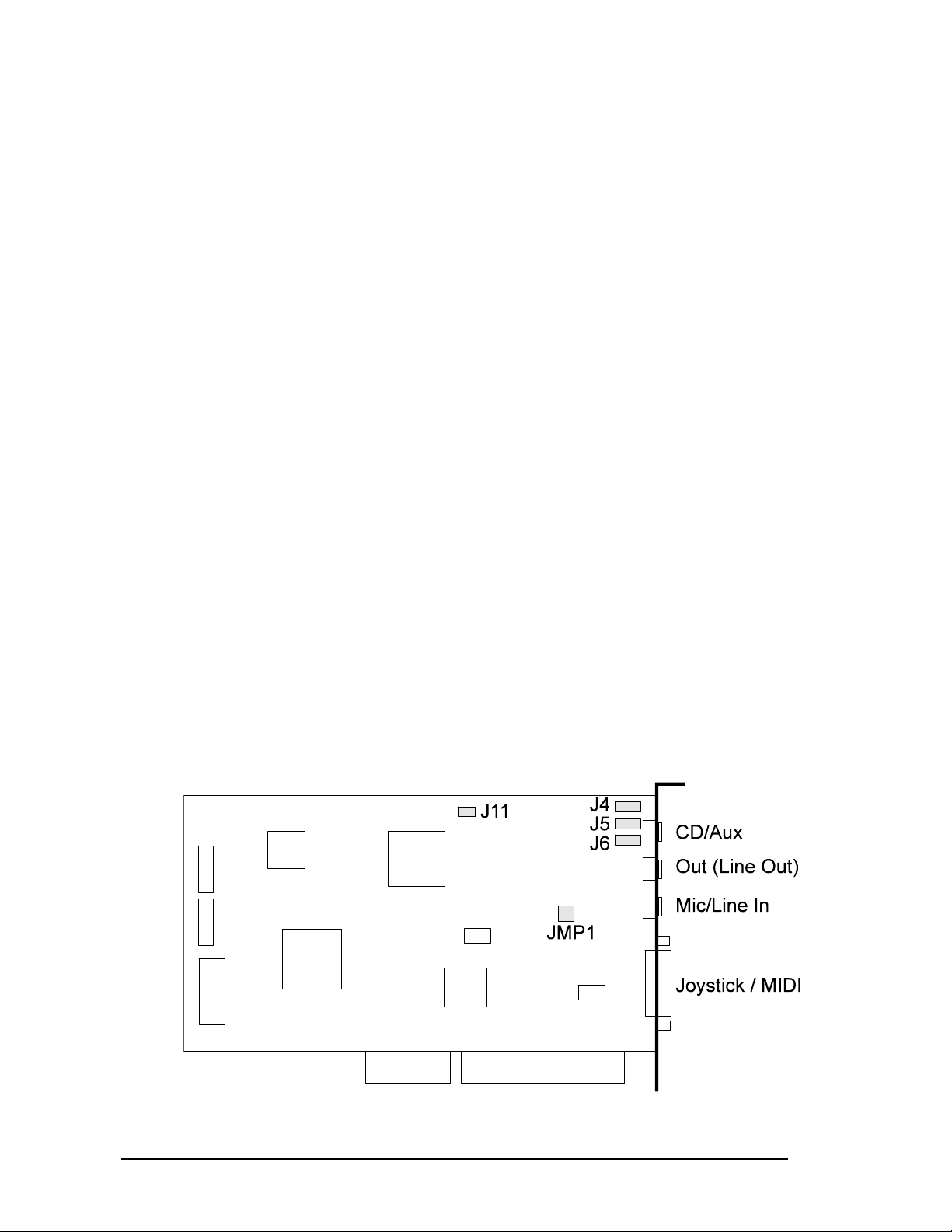
Jumper Locations and Functions
Do not change the SPEA MEDIA XTC default
jumper settings unless you are certain it is
necessary (that is, if one or more of the four
conditions listed above are met) - and if you do
change a jumper location, be sure to make a
note of it so that you can make appropriate
selections when installing the software. To
remove a jumper, grip it with a small pair of
needlenose pliers and lift straight up (you can
gently rock it back and forth if you meet any
resistance). To replace it, position it over the
desired pin(s) and press down gently but firmly
until it is seated in place.
Following is a description of the SPEA MEDIA
XTC jumper.
JMP1 Phantom Power Supply for
Microphone & Stereo / Mono Microphone
This jumper is used to connect 2.5 volt
phantom power to the Mic/Line input jack and
for configuring a Stereo or mono microphone.
Leave this jumper off when using a dynamic
microphone or a battery powered electret
condenser microphone. Place the jumper on
pins 1-2 when using an electret condenser
microphone without a built-in battery.
Jumper on: None: Phantom supply
not connected
(default)
Pins 1-2: Phantom supply
connected
When using a Stereo microphone remove the
jumper from the pins 3-4.
Jumper on: None: Stereo
microphone
Pins 3-4 Mono microph.
(default)
SPEA MEDIA XTC connection possibilites
10
Page 11

External Audio Connectors
Internal Audio Connectors
Below is a listing of the external connectors
found on the back of the SPEA MEDIA XTC
card. Consult the illustration on the preceding
page for connector locations.
CD/Aux:
This is a line level input which accepts a 1/8"
TRS stereo plug. It can be used as a source for
digital sound recording, a source to be mixed
with the output, or both.
Out:
This is a stereo line level output through which
the combined signal of all internal and external
audio sources on the board is output. It can be
connected to Walkman-type (1/8" TRS stereo)
headphones or to amplified speakers.
Mic/Line In:
This is a 1/8" mono jack which provides a
switchable line or microphone level input
(select one or the other in the SSINIT.EXE
program Mixer module). It can be used as a
source for digital sound recording, a source to
be mixed with the overall output signal, or both.
Note:
Using the Mic/Line input in 'Mic' mode provides
an additional 20 dB of input signal gain.
Joystick/MIDI:
This is a 15-pin D-sub connector. It can be
used with standard MIDI adapters and joystick
connectors. The joystick interface will support
both single and dual joysticks.
Tip
When connecting a stereo system to your PC
make sure that both devices use the same
mains circuit (use a multi-socket). This
eleminates the potential risk of mains noise.
The following describes all internal audio
connectors of the SPEA MEDIA XTC board.
The internal audio connectors can be used to
make a connection e.g. to a TV Tuner board or
an MPEG playback board within the PC. For
the positioning of the connectors please have a
look at the illustration one page before.
TV / Sony CD/ATAPI-CD (J4):
Input with Line Level. An audio connector is
used which is used for Sony and many ATAPI
drives.
The pinout is:
If you look at the SPEA MEDIA XTC, so that
the bus connector is below (and the labelling of
the board is readable), then the right pin is pin
#1 and the left pin is #4.
pin 1 right
pins 2,3 ground
pin 4 left
Mitsumi CD (J5)
Input with Line Level. An audio connector used
by Mitsumi is used.
The pinout is:
If you look at the SPEA MEDIA XTC, so that
the bus connector is below (and the labelling of
the board is readable), then the right pin is pin
#1 and the left pin is #4.
pin 1 right
pins 2,4 ground
pin 3 left
Matsushita CD (J6)
Input with Line Level. An audio connector used
by Matsushita is used.
The pinout is:
If you look at the SPEA MEDIA XTC, so that
the bus connector is below (and the labelling of
the board is readable), then the right pin is pin
#1 and the left pin is #4.
pins 1,3 ground
pin 2 left
pin 4 right
11
Page 12
Modem In (J11)
Input with Line Level. Here you can connect a
Line Output of a modem.
Thus, you can control the volume of the
modem via the mixer and, if necessary, you
can record signals from the modem input.
The pinout is:
If you look on the SPEA MEDIA XTC, so that
the bus connector is below (and the labelling of
the board is readable), then the right pin is pin
#1 and the left pin is #2.
pin 1 signal
pin 2 ground
Installing the SPEA MEDIA
XTC Card
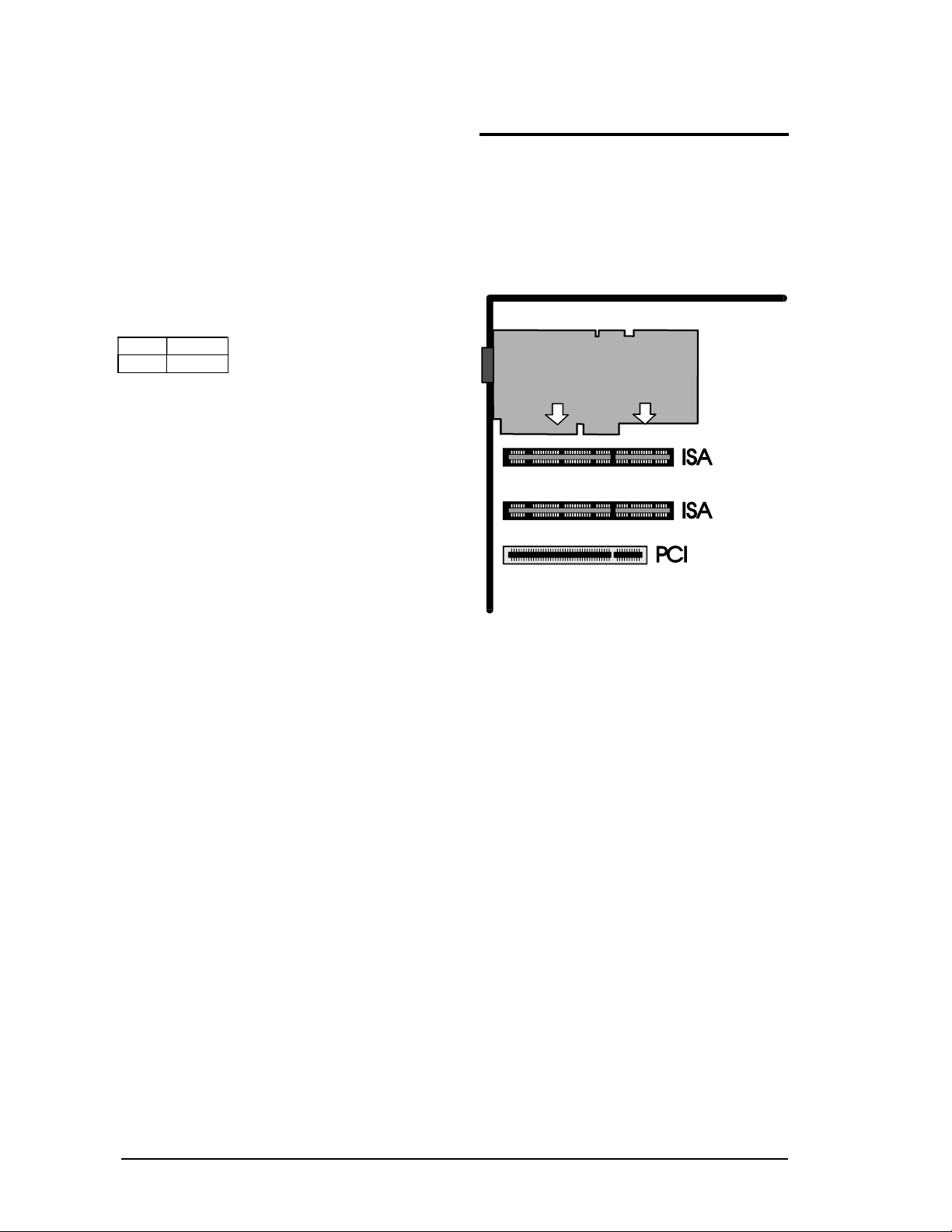
1. Remove the cover to your computer. Your
SPEA MEDIA XTC card can be installed in
any available 16-bit expansion slot. A 16-bit
expansion slot can be identified by its
double connector:
2. Remove the metal expansion slot cover for
the selected slot. Save the screw for
installing the board.
Installation of the SPEA MEDIA XTC in an ISA
expansion slot
3. Hold the SPEA MEDIA XTC card by the
edges and press the connector gently but
firmly into the expansion slot.
4. Align the notch in the mounting bracket of
the SPEA MEDIA XTC card with the screw
hole in the rear panel of the computer case.
Use the screw that you removed from the
metal expansion slot cover to secure the
SPEA MEDIA XTC card in place. This step
is important for proper grounding of the
card.
5. Secure all internal cables before you
replace the computer cover. If you are
installing an internal CD-ROM drive, make
sure you connect it properly.
6. Replace the computer cover.
7. Reconnect any peripheral equipment cables
that you may have previously disconnected.
8. Make the audio connections you desire to
SPEA MEDIA XTC’s inputs and outputs.
9. If you wish to use a joystick, a MIDI device,
or both, connect an adapter cable to the
SPEA MEDIA XTC Joystick/MIDI port.
12
Page 13

Software Installation
After fitting the SPEA MEDIA XTC card, it is
necessary to install the software. We
recommend that you make a copy of your
master disks and put the originals away in a
safe place, using the copies for the rest of this
procedure (consult your DOS manual for disk
copying instructions). Approximately 5
megabytes of space on your hard disk is
required to install all of the SPEA MEDIA XTC
software.
Be sure to read the section titled Tips for
Successful Installation later in this section prior
to making any changes to the default
selections. Doing so will save you time and
ensure proper operation.
Software Installation Procedure for
DOS / Windows 3.1xx
The following installation procedure must be
executed from the Windows Program
Manager:
1. Insert SPEA MEDIA XTC Installation Disk 1
into your floppy disk drive.
2. From the Windows File menu, choose Run.
3. If your system’s 3.5" floppy drive is
configured as drive A, type A:SETUP in the
Run dialog box; if it is configured as drive B,
type B:SETUP in the Run dialog box.
4. Follow the instructions on the screen. Click
on the Cancel button to abort the
installation procedure, or click on the Exit
icon at the bottom right of the screen at any
time to exit the Setup program.
5. After a few moments, you will be prompted
to insert the SPEA MEDIA XTC Installation
Disk 2 into your floppy disk drive. Do so and
then click on OK or press the Enter key.
6. You will be returned to the Windows
Program Manager and a dialog will ask you
if you wish to add a Level Control Utility to
your startup program group. If you click on
Yes (or press the Enter key, a SPEA
MEDIA XTC level control slider (which
allows you to adjust the SPEA MEDIA XTC
overall master volume) will appear onscreen
each time you start up Windows. If you click
on No, this Level Control Utility will be
added instead to the SPEA MEDIA XTC
program group and can be activated any
time it is required.
Note:
If you do opt to place the Level Control
Utility in your startup group and later change
your mind, you can always move it out of
the startup program group and into the
SPEA MEDIA XTC program group; this will
have precisely the same effect as if you had
selected No in the first place.
7. Be sure to look at the README file at the
end of the installation procedure for up-todate changes in the SPEA MEDIA XTC
software.
8. The computer must be re-booted after
installation in order for the SPEA MEDIA
XTC card to work.
13
Page 14

Standard Modifications
The installation procedure makes the following
modifications to your start-up files:
AUTOEXEC.BAT
The following lines will be inserted into your
AUTOEXEC.BAT file:
SET BLASTER=A220 Ixx Dx T1
SET MEDIAXTC=dirname
dirname\SSINIT GM
Where:
SET BLASTER is included for Sound Blaster
compatibility and should not be removed. The
x's in this entry will be dynamically altered by
the SPEA MEDIA XTC configuration program.
Note:
During the installation, you will be asked if you
have a SoundBlaster or similar card installed in
your system. If you answer yes, the SET
BLASTER line will not be written to your
AUTOEXEC.BAT file.
SET MEDIAXTC is included so that your SPEA
MEDIA XTC configuration program knows
where to find certain files. dirname corresponds
to the SPEA MEDIA XTC directory i.e.,
C:\MEDIAXTC.
dirname\SSINIT GM initializes the SPEA
MEDIA XTC card to General MIDI mode at
boot time. dirname corresponds to the SPEA
MEDIA XTC directory, i.e., C:\MEDIAXTC.
Note:
If any of the above entries are removed, your
system will not be able to properly initialize your
SPEA MEDIA XTC card.
SYSTEM.INI
The SPEA MEDIA XTC installation modifies
the SYSTEM.INI file in your WINDOWS
directory, adding [sndscape.drv] sections as
well as adding the following lines to the
[drivers] and [386Enh] sections.
[drivers]
Wave= C:\SPEA\MEDIAXTC\SNDSCAPE.DRV
Aux= C:\SPEA\MEDIAXTC\SNDSCAPE.DRV
Mixer= C:\SPEA\MEDIAXTC\SNDSCAPE.DRV
MIDI= C:\SPEA\MEDIAXTC\SNDSCAPE.DRV
[386Enh]
device=VVDMAD.386
Note:
Do not edit or alter this file unless you are
absolutely certain you know what you are
doing!
In both the [386Enh] and [drivers] section,
there may be drivers installed that conflict with
SPEA MEDIA XTC. If the install program
detects these, it will comment them out
(showing you that the modification has been
made).
MIDIMAP.CFG
The SPEA MEDIA XTC installation places a
new MIDIMAP.CFG file in your
WINDOWS\SYSTEM directory and renames
your old MIDIMAP.SND file. To restore the
MIDI Mapper to its prior state, simply delete the
new MIDIMAP.CFG file and rename the
MIDIMAP.SND file MIDIMAP.CFG. For more
information, see Part 4 in this manual.
Tips for Successful Installation
Here are some additional things to be aware of
when installing the SPEA MEDIA XTC
software:
Do not change default IRQ and DMA
settings unless you are aware of an
immediate conflict and have a thorough
understanding of what they do and how
they work.
14
Page 15

Part 3
Configuring the
SPEA MEDIA XTC
If you need to alter one or more of the SPEA
MEDIA XTC settings, then use the utilities
described in the following sections.
Configuring Your SPEA MEDIA
XTC Card under DOS
The SPEA MEDIA XTC contains the hardware
and software necessary to support the
following popular music options:
- General MIDI - provides an MPU-401
compatible General MIDI synthesizer
- MT-32 provides Roland MT-32 emulation
utilizing the on-board synthesizer.
Note:
Some games apply custom programming to
the MT-32 sounds. The MT-32 emulation of the
SPEA MEDIA XTC cannot accomodate all
custom programming. Therefore, some sounds
may sound different that when played back
using a real MT-32 and, in extreme cases,
some sounds may not be heard at all.
Note:
Games and multimedia applications should not
be run from Windows unless they are
specifically Windows of MPC compatible.
Similarly, DOS games and multimedia
applications should not be run from a DOS
session under Windows - run them from DOS
only.
There are many versions of the Sound Blaster
card. For programs that offer separate Sound
Blaster and Sound Blaster Pro selections, use
the Sound Blaster option.
The SPEA MEDIA XTC is not compatible with
games (very few) that require Sound Blaster
ADPCM (Adaptive Differential Pulse Code
Modulation).
15
Page 16

Using SSInit
Note:
The SSInit program cannot be run from
Windows, nor can it be run from a DOS
session under Windows.
The SPEA MEDIA XTC DOS configuration
program is called SSINIT.EXE, located in the
SPEA MEDIA XTC installation directory
(normally C:\MEDIAXTC). SSInit allows you to
set the operating mode, configure the SPEA
MEDIA XTC hardware parameters, and adjust
mixer controls. To launch SSInit:
1. Go to the SPEA MEDIA XTC installation
directory. E.g., type:
CD C:\MEDIAXTC
2. Launch SSinit by typing
SSINIT
At this point, a graphical user interface
(described in the following section), will appear.
Notes:
Typing SSINIT /I will initialize the SPEA MEDIA
XTC to ist default state without presenting the
hardware configuration interface
In order to take advantage of all the SSInit
configuration options, a mouse should be
installed under DOS.
The SSINIT program cannot be run from
Windows, nor can it be run from a DOS
session under Windows.
Hardware Configuration Interface
(SSINIT)
The SSInit program provides four screens for
configuring the SPEA MEDIA XTC: Quick
Setup, Hardware, Mixer, and Synth. On-line
help is available for any screen by simply
pressing F1 on your keyboard while viewing the
screen with which you need help.
16
Page 17

17
Quick Setup Screen
The Quick Setup screen, shown below, is the
first screen that appears after launching SSInit.
This screen allows you to quickly configure
some of the SPEA MEDIA XTC volume
settings and to set the operating mode.
The following configuration options are
available in the Quick Setup Screen:
Master Volume
simultaneously adjusts the level of all playback
sources (a mouse is required to adjust this
parameter). The default is 127.
Synth/Music Volume
sets the playback volume of the synthesizer
only (a mouse is required to adjust this
parameter). The default is 100.
Wave/Sound
sets the digital audio playback volume only (a
mouse is required to adjust this parameter).
The default is 127.
Using Advanced Settings
When you select Advanced from the Quick
Setup screen, the values selected in Quick
Setup are entered and you can now access
any of four additional screens - Hardware,
Mixer, Synth, or Exit - by clicking the menu
selection at the top of the screen or by holding
down the Alt key and typing the highlighted
letter corresponding to the menu you wish to
select. When the menu appears, click on the
setting you wish to change or type the
highlighted letter to select it, and adjust as
required.
Note:
Most menu selections can be altered using a
combination of key sequences. The Tab key
will move you between fields of the menu. The
Up Arrow and Down Arrow keys will let you
select items in a field. The Space key will
select or deselect items in a check box. Sliders
(i.e. Volume controls) can only be adjusted with
your mouse.
When you finish making adjustments and you
wish to save them, click OK (or type O). If you
wish to discard your changes, click Cancel (or
type C). After you finish making all necessary
adjustments, click the Exit selection in the
menu bar (or type Alt+X) to exit SSInit.
Page 18

Hardware Settings Screen
The Hardware Settings screen configures the
hardware settings that determine how SPEA
MEDIA XTC communicates with your
computer.
MIDI Interface
This box enables you to set the basic hardware
parameters for your SPEA MEDIA XTC card.
Port selects the MIDI interface port address
used by SPEA MEDIA XTC—this also
corresponds to the MPU-401 MIDI interface
base port address. The default is 330.
IRQ selects the interrupt request line that the
SPEA MEDIA XTC synthesizer and MPU-401
compatible MIDI interface will use for basic
communications. The default is 2. This IRQ
value must be different than the IRQ value
selected in the Sound Blaster/Wave section of
the Hardware Settings screen.
Note:
IRQ 2 is the default IRQ setting for an MPU401 in many DOS applications. Some
applications may not work with a different
selection.
Note:
Setting the IRQ value to 10 will cause SSInit to
generate a warning message since IRQ 10 is
not a legitimate MPU-401 IRQ for some DOS
applications. However, this will not affect
SPEA MEDIA XTC's operation under Windows.
Joystick
Joystick enables or disables the Joystick port
on your SPEA MEDIA XTC card. The default
is Disabled. Enable the Joystick port only if
your system has no other joystick card.
Sound Blaster/Wave
This box enables you to set SPEA MEDIA
XTC's Sound Blaster compatibility parameters.
Note:
The SPEA MEDIA XTC Sound Blaster
emulation uses a fixed base port address of
220. Therefore, if you are running a DOS
game or multimedia program that provides only
for Sound Blaster compatibility, make sure that
program expects to find a “Sound Blaster” card
at Base Port address 220.
SB Emulation enables or disables Sound
Blaster mode. This option should be turned off
only if you have a Sound Blaster or Sound
Blaster-compatible card in your system. The
default is Enabled.
Note:
During the installation, you will be asked if you
have a Sound Blaster or similar card installed
in your system. If you answer yes, the SET
BLASTER line will not be written to your
AUTOEXEC.BAT file and SB Emulation will be
disabled. If you later turn this switch on, make
sure you add the following line to your
AUTOEXEC.BAT file: SET BLASTER=A220
Ixx Dx T1.
IRQ selects the interrupt that will be used for
Sound Blaster digital audio emulation. The
recommended IRQ setting is either 7 or 5. This
IRQ setting is also used by SPEA MEDIA
XTC’s wave device under Windows.
DMA selects the DMA (Direct Memory Access)
channel that SPEA MEDIA XTC uses for board
initialization and digitized sound transfer. This
setting also determines the DMA selection for
Sound Blaster digital audio emulation and the
DMA channel for SPEA MEDIA XTC’s wave
device under Windows. The default is 1.
Note:
Settings changed in the 'MIDI Interface and
Sound Blaster/Wave' boxes will be reflected in
your Windows Driver setup box. See
“Configuring SPEA MEDIA XTC under
Windows” in the SPEA MEDIA XTC manual.
Conversely, changes made to your
configuration in the Windows driver setup box
will be reflected in the Hardware Settings
screen.
18
Page 19

Hardware Test Screen
This screen allows you to resolve conflicts in
your system that may affect proper operation of
the SPEA MEDIA XTC card. From this screen
you can perform either an IRQ or a DMA test
on your system to help resolve any conflicts.
The tests use information obtained from the
Hardware settings page to test the current IRQ
and DMA selections. If you make an IRQ or
DMA change in the Hardware settings page,
you can test them from this screen. To run the
IRQ test, select “IRQ test”. To run the DMA
test, select “DMA test”.
IRQ and DMA Test Screens
Running the IRQ test displays the current IRQ
settings reflected in the Hardware page. After
the test is complete, you can make changes on
the Hardware Settings screen.
Running the DMA test displays the current
DMA channel settings reflected in the
Hardware page. After the test is complete, you
can make changes on the Hardware Settings
screen.
Mixer Settings Screen
This screen allows you to adjust all of the audio
levels on the SPEA MEDIA XTC card.
Master Volume
adjusts the overall output volume of the sound
card. The default is 127.
CD/Aux Volume
Adjusts output level of the CD or Auxiliary
audio input. The default is 96.
Mic/Line Volume
Mode allows you to choose either line-level or
mic-level input. Select line when connecting a
device such as a cassette deck, tape recorder,
or when routing signal from a home stereo
amplifier. Select mic when a connecting a
microphone.
Left adjusts the left output level of the Mic/Line
input. The default is 32. Right adjusts the right
output level of the Mic/Line input. The default is
32.
Synthesizer Volume
adjusts the output level of the SPEA MEDIA
XTC synthesizer. The default is 127.
Wave/Sound Volume
adjusts the digital audio output level. This
setting will also affect the Sound Blaster digital
audio emulation. The default is 96.
Note:
For parameters with separate left and right
controls (i.e. CD/Aux Left Volume/ Right
Volume), both controls will move together when
either one is moved. Either control may be
moved independently by holding down the
SHIFT key while moving it.
19
Page 20

Exit Screen
When you have finished making changes and
wish to leave SSInit, select the Exit item on the
top of the screen, or type Alt+X. If any configuration values have been changed, the Exit
screen shown below will appear.
Change Sound Card Settings
When this box is checked, the changes you
just made in SSInit will be applied to the SPEA
MEDIA XTC card.
Change Default Settings
When this box is checked, the changes you
just made in SSInit will be applied to the SPEA
MEDIA XTC card and also will be saved to an
initialization file so that they are reflected in
subsequent uses of SSInit.
Selecting OK will perform the changes
indicated by the check box selections and then
exit SSInit. If you would like to quit SSInit
without applying any of your changes, deselect
both check boxes and select OK.
Selecting Cancel will abort the Exit screen and
allow you to continue making configuration
changes in SSInit.
20
Page 21
MT32 Patch-change Utility
The MT-32 was a popular sound module in the
late 1980’s (prior to the General MIDI standard)
which provided superior sound over the PC
sound systems that were available at that time.
During that period, many game manufacturers
supported the MT-32 as their high-end sound
device.
Type this (from a DOS prompt) To have this effect
MT32
or
MT32 ON switches patches to Roland MT-32
Patch Set
MT32 OFF switches patches to General MIDI
Patch Set
How to use the MT32 Patch-change Utility
SPEA MEDIA XTC Digital Audio/MIDI
Test Utility
The SPEA MEDIA XTC Digital Audio/MIDI Test
Utility is a resource you can use to help identify
common problems related to DMA, IRQ and
port settings. To run the test, simply type
DMTEST.EXE
from within your SPEA MEDIA XTC directory.
The test sequence begins with initialization of
the board followed by a test of the digital audio
hardware. If you get a “Board not detected”
message during initialization, check the port
settings on the Hardware Settings screen of
SSinit and make adjustments as needed.
The two possible error messages during the
digital audio hardware test are “DMA error” and
“IRQ error”. If either occurs, use the Hardware
Settings screen to evaluate and/or reassign
DMA and IRQ settings.
Upon completion of the hardware test, you are
prompted to press any key to initiate the digital
audio test. As soon as you press a key, you will
hear a sound effect, indicating that the test was
successful.
After completing the digital audio test, you can
either run the MIDI hardware portion of the test
or repeat the first test. Pressing the letter “c”
initiates the MIDI hardware test. A “MIDI port
not detected” message means that the board
was not initialized, in which case you should
reinitialize it by typing:
SSINIT/I
from within the SPEA MEDIA XTC directory
(this is different from the initialization
SPEA MEDIA XTC provides two sets of
patches: a General MIDI compatible patch set
and a patch set which emulates a Roland MT32 sound module. These patches cannot be
used simultaneously, so a utility called MT32 is
provided to allow you to easily switch from one
patch set to another. Use this utility whenever a
game supports MT-32 as a music/sound
option. The usage for MT32 is as follows:
performed at the beginning of the test
sequence).
The only other possible error message for this
test is the “IRQ error” message. If it appears,
use the Hardware Settings screen of SSinit to
re-evaluate your IRQ selections.
Upon completion of the MIDI hardware test,
you will be prompted to press any key to initiate
the MIDI audio test. As soon as you press a
key, you will hear a sound effect, indicating that
the test was successful. Like the digital audio
test, you can repeat this test as often as you
like. Once the test sequence is completed, the
“SPEA MEDIA XTC Digital Audio Test
Complete” message appears.
S2KStat Diagnostic Utility
S2KStat is a diagnostic utility that can be used
to simplify the process of setting up games.
This utility keeps track of commands that are
sent to the SPEA MEDIA XTC and, when run,
will display a list of these commands. You can
use S2KStat to determine if SoundBlaster, FM
or MPU-401 (GM) commands are being
received by the SPEA MEDIA XTC.
To use S2KStat, type S2KStat from the
MEDIAXTC directory. The utility will respond by
displaying a list of commands and the status,
either Activitiy or No Activity. You can then
use this information to help you decide which of
these modes is working with a particular game.
If you use S2KStat, be sure to run it
immediately after running a program to insure
that the data it displays is accurate.
A typical usage of the S2KStat utility would be
as follows. You are running a game but hear no
sound. You then run S2KStat and see that the
card was not receiving any SoundBlaster
21
Page 22

commands. When you check the game's
Sound Blaster settings, you see that they
change the game's setting to match those of
the SPEA MEDIA XTC to correct the problem.
22
Page 23

Using the Intel ISA Configuration
Utility (ICU)
The ICU is provided to allow you to view and
change the hardware configuration of plug &
play devices such as SPEA MEDIA XTC. You
can change:
the MIDI IRQ
Wave IRQ
DMA1
DMA2
MIDI Interface Port address
Since SPEA MEDIA XTC comes preconfigured, it will not be necessary to alter
these basic settings in most cases. However, if
you feel that it is necessary to make changes
to the hardware configuration of the SPEA
MEDIA XTC, you can use the ICU to do so. It is
located in the \PLUGPLAY\ICU directory. Help
files are included. Be sure to carefully read this
information before attempting to reconfigure
your card. Following is a brief summary of how
the ICU works. Again, consult the ICU help files
for more detailed information.
When the ICU runs, you are presented with a
screen listing of all of the known devices
installed in your system. To view the SPEA
MEDIA XTC settings, double click in the SPEA
MEDIA XTC device.
The SPEA MEDIA XTC setup is divided into
three logincal devices:
Logical device 0 is the SPEA MEDIA XTC
hardware settings (MIDI IRQ, DMA, etc.)
Logical device 1 is the SoundBlaster emulation
Logical device 2 is the joystick.
Logical device 0 defaults the most common
settings. You can use the ICU to change these
settings. If you change them, consider also
locking them (that is protecting them from
reassignment) to make setting up games
easier. Within logical device 0 are four choices,
each containing a configuration set. The
configuration sets are as follows:
Choice MIDI
IRQ
1
2
3
4
Disabled (never select this as an option)
Choices 1-3 are hard-coded and the individual
components cannot be changed. Choice 4,
however, is not hard-coded, and the individual
components within can be reconfigured. To
enable/disable the joystick and SoundBlaster
emulation, use logical devices 1 and 2
respectively.
9 5 1 3 330-
7 5 1 3 330-
10 9 1 3 330-
7 5 0 1 350-
Wave
IRQ
DMA1 DMA2 Add
ress
33F
33F
33F
35F
23
Page 24
Configuring Your SPEA MEDIA
XTC Card under Windows
The SPEA MEDIA XTC software installation
process installs all required Windows wave and
MIDI drivers. These drivers allow you to run
standard Windows Multimedia applications.
Note that, under Windows, the SPEA MEDIA
XTC card will operate in General MIDI (GM)
mode only (see Part 4 in this manual for more
information).
Because Windows provides a standardized
method of communicating with sound devices,
the following two rules must be obeyed.
Do not run any DOS based sound
applications (e.g., games, DOS sequencers,
etc.) under Windows.
Do not run any applications under Windows
that are not Windows Multimedia compliant.
Applications that are compliant will usually
be referred to as 'Multimedia for Windows',
'MPC (Multimedia PC)', or something
similar.
The SPEA MEDIA XTC Windows driver
inherits all the hardware settings made by
SSInit and also offers some additional
configuration functionality that is not addressed
by the SSInit program. If you will be using
SPEA MEDIA XTC with Windows applications,
we recommend that you run the Windows
driver setup routine following installation in
order to view all hardware configuration
settings and to make any necessary changes.
To open the SPEA MEDIA XTC Windows
driver setup display:
1. Open the Main program group under the
Windows Program Manager.
2. Open the Control Panel applet inside the
Main program group.
3. Inside the Control Panel double click on
the SPEA MEDIA XTC symbol.
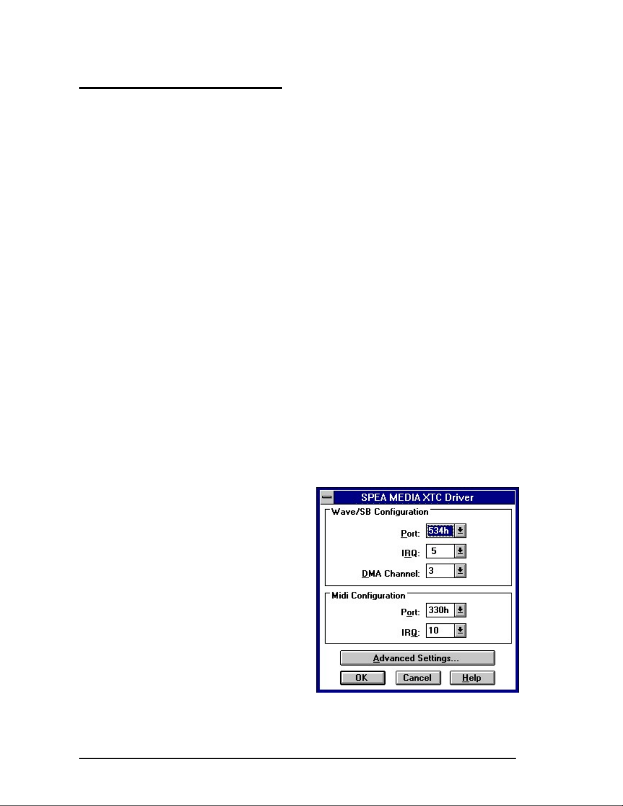
The SPEA MEDIA XTC Windows driver setup
display is shown below in its default state.
The top half of the setup display presents the
configuration options for the Primary Wave
Record/Playback device. This is the area of
the SPEA MEDIA XTC used for the recording
of digital audio soundfiles and the playback of
monophonic digital audio soundfiles.
The bottom half of the setup display presents
the configuration options for the MIDI Synth
and Secondary Wave Playback device. The
Secondary Wave Playback device is a unique
feature of SPEA MEDIA XTC which extends
the sound-file playback capability of Windows,
allowing up to three wave files (instead of just
one) to be played back simultaneously. The
SPEA MEDIA XTC is fully compatible with
Windows Multimedia applications even without
this extended capability. By default, Secondary
Wave Playback is disabled since it requires the
use of additional DMA resources. However, if
you know that your system has additional DMA
resources available, you can enable one or
both of the Secondary Wave Playback devices,
as described below.
Primary Wave Record/Playback
Setup
Port
selects the base port address of the SPEA
MEDIA XTC Primary Wave Record/Playback
device. This corresponds to the WavePort
selection made in the Hardware Setup screen
of SSInit (SPEA MEDIA XTC DOS
configuration utility).
Interrupt
selects the interrupt request line (IRQ) of the
SPEA MEDIA XTC Primary Wave
Record/Playback device. This value
corresponds to the IRQ selection made in the
SB IRQ/Wave section of the Hardware Setup
screen of SSInit. The default is 5.
DMA Channel
selects the DMA channel that the SPEA
MEDIA XTC Primary Wave Record/Playback
device will use for wave (digital audio) data
transfer. This value corresponds to the DMA
selection made in the Hardware Setup screen
in SSInit and is also the DMA channel that is
used when the SPEA MEDIA XTC emulates
Sound Blaster digital audio under DOS. The
default is 1.
SPEA MEDIA XTC Wave and MIDI
Configuration
24
Page 25
MIDI Synthesizer
Port
selects the base port address of the SPEA
MEDIA XTC synthesizer and MPU-401
compatible MIDI interface. This value
corresponds to the BasePort selection made in
the Hardware Setup screen in SSInit.
Interrupt
selects the interrupt request line that the SPEA
MEDIA XTC synthesizer and MPU-401
compatible MIDI interface use for basic
communications. This value corresponds to the
IRQ selection made in the Base Values section
of the Hardware Setup screen of SSInit. The
default is 2.
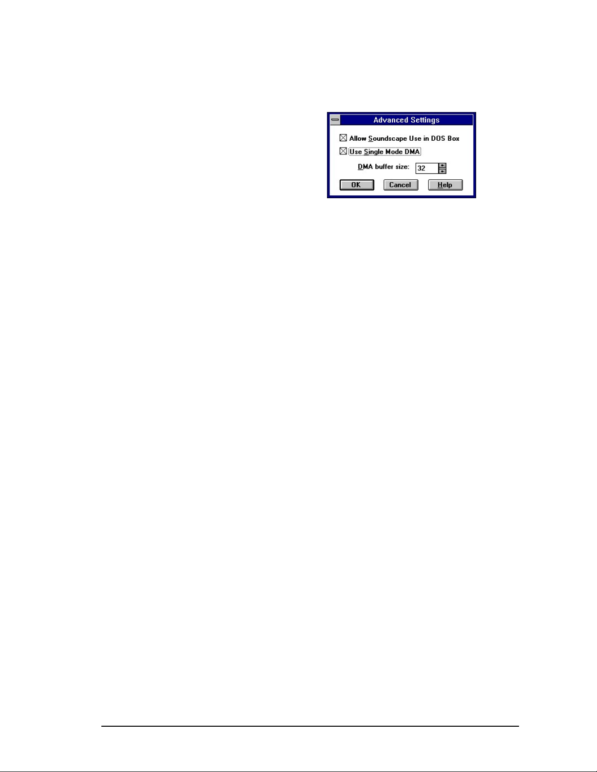
The Advanced Settings Display
The Advanced Settings display can be used to
make additional adjustment to the SPEA
MEDIA XTC driver.
Advanced Settings Dialogue Box
Allow SPEA MEDIA XTC Use in DOS Box
enables or disables the SPEA MEDIA XTC
card in a DOS shell under Windows (allowing
you to play DOS games under Windows). It is a
good idea to leave this option enabled. Disable
it if you are using a DOS program that uses
sound in conjunction with a Windows program
that also uses sound.
Use Single Mode DMA toggles the DMA
mode from Single to Demand mode. Demand
mode DMA is used for compatibility with certain
mother boards. If digital audio playback is not
working, turn off Single mode DMA.
DMA buffer size allows you to change the size
of the DMA buffer allocated to the SPEA
MEDIA XTC driver. Generally, a DMA buffer
size of 32 is sufficient. If you are doing large
amounts of digital audio playback or video
playback, increasing this value may improve
performance.
OK saves any changes you have made and
exits the display.
The Cancel button exits the Advanced Settings
display without applying changes.
The Help button brings up help screens
explaining the display.
25
Page 26

PART 4 Configuration of
the SPEA MEDIA XTC
under Windows® 95
The SPEA MEDIA XTC is easiest to use when
installed in a plug-and-play system, i.e. When
installed in the Windows® 95 operating
environment, SPEA MEDIA XTC requires a
minimal amout of configuration by the user.
Installing the SPEA MEDIA
XTC in a Windows® 95 System
To install the SPEA MEDIA XTC in a
Windows® 95 system, follow these steps:
1. Shut down your computer.
2. Place the card into your computer. Refer to
the installation section earlier in this manual
for details.
3. Restart your computer. W indows® 95 will
automatically detect the presence of the
new hardware and prompt you for the
location of the driver for the SPEA MEDIA
XTC hardware.
4. Insert the SPEA MEDIA XTC disk #1 or
SPEA CD and click OK or press Enter. The
installation program will place the SPEA
MEDIA XTC driver and other software onto
the selected drive. The driver will be
installed with the best possible configuration
for your particular system. This
configuration will be selected based on
other devices in your computer.
5. Be sure to select the Windows® 95 joystick
driver to ensure proper function of the
joystick, if you are using one.
Using the SPEA MEDIA XTC
with DOS games
There are two ways to launch DOS games in
Windows® 95: from a DOS box or from the
DOS Exclusive Mode. The DOS box method of
launching games will yield the best SPEA
MEDIA XTC performance.
To use a game in a DOS box:
1. Start by viewing SPEA MEDIA XTC' s
current DOS Settings (DMA, IRQ, and
Address settings). This information will
allow you to make appropriate choices
when you set up the game.
2. To view the current settings, right click on
the 'My Computer' icon. The System
properties page appears.
3. Click on the Device Manager tab to display
the list of devices in your computer.
4. Double click on the 'Sound, video and game
controllers' icon to see the list of devices.
5. Double click on the 'SPEA MEDIA XTC'
device icon. The SPEA MEDIA XTC
Properties page appears.
6. Click on the DOS settings tab to view the
settings. It may be helpful to make a note of
them for future reference.
7. Start a Virtual Machine Session (DOS
Session) by clicking on Start in the Taskbar,
the Programs from the subsequent pop-up
menu, and finally the MS DOS Prompt from
the next pop-up menu.
8. Again, be sure to set up your game based
on the DOS Settings Property page of the
SPEA MEDIA XTC driver to ensure proper
performance.
To use a game in DOS Exclusive
Mode:
Again, the DOS Box method is preferred.
1. Bring up the Properties page for the game's
executable (.EXE).
2. Select the Program Properties page.
3. Select Advanced.
4. Check MS-DOS Mode.
5. Check Specify a new MS-DOS Configu-
ration. If the game is set up for MT-32
mode, click the configuration button and
select SPEA MEDIA XTC MT-32 Mode.
This will build a CONFIG.SYS and
AUTOEXEC.BAT file that is associated with
that .EXE. When you double click on the
program's icon, it will restart the system using
these new settings and run the game. When it
is finished, Windows will reload. Be aware that
the DWCFGMG.SYS driver must load in order
26
Page 27

27
for the SPEA MEDIA XTC card to work in DOS
Exclusive Mode.
Page 28
Using the Mixer
The Mixer is a feature of Windows® 95 that
lets you make a variety of adjustments to the
audio levels and balance of the SPEA MEDIA
XTC. To view the mixer, work your way through
the hierarchy of pop-up menus beginning with
the Start button of the task bar. The sequence
is Programs, Acessories, Multimedia, and
Volume control (mixer). Rather than going
through this sequence each time you want to
make an adjustment of SPEA MEDIA XTC's
audio levels, you can place the mixer in the
task bar by following these steps:
1. Open the Control Panel.
2. Double click on the Multimedia icon. The
multimedia properties page appears,
3. In the playback section, check the box
marked Show volume control in the task
bar. The mixer can now be invoked by
double clicking on the small speaker icon
located on the right side of the taskbar next
to the clock. Single clicking on this icon will
bring up a smaller page that lets you adjust
the volume.
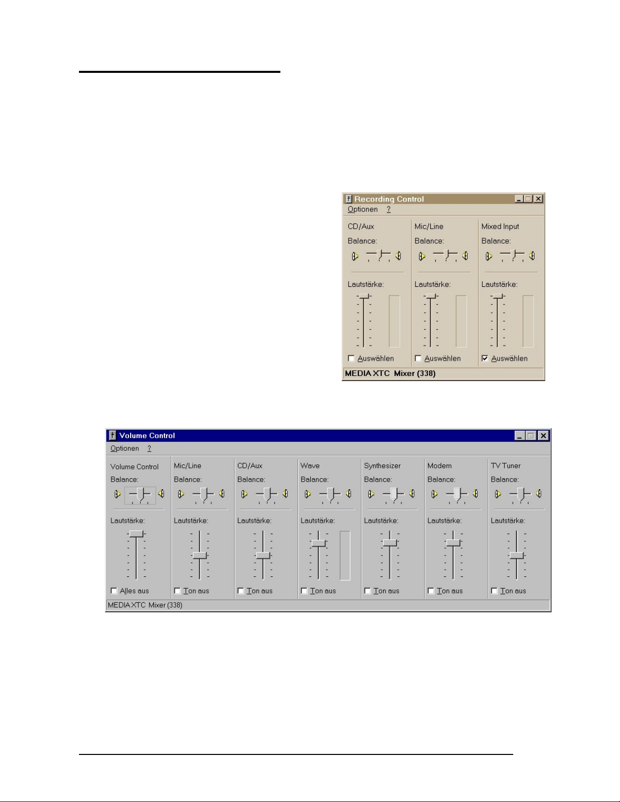
The mixer, shown below, can display all
sections or only a portion of them. Which
sections are displayed can be changed by
choosing the Properties item of the Options
menu. In addition to controlling the audio
performance of the SPEA MEDIA XTC for
Windows applications, the mixer can also
control DOS volumes. If you are running a
game and want to adjust the volume, simply
switch back to Windows by pressing Alt + Tab
(you must be in a DOS box) and adjust the
mixer.
Mixer for the SPEA MEDIA XTC
Mixer for the SPEA MEDIA XTC while
recording
28
Page 29

Locking Configurations under
Windows® 95
Uninstalling the SPEA MEDIA
XTC Software
In some situations, it may be a good idea to
lock your SPEA MEDIA XTC configuration. For
example, you may want to insure that a
particular DOS game is compatible with the
SPEA MEDIA XTC. DOS games usually have
a setup program which is run prior to playing
the game. In the setup program, you tell the
game what type of sound card you have as well
as what resources the sound card uses. Due to
the dynamic nature of a plug & play system,
you can't always guarantee that the settings the
operating system assigns to the card will be the
same from session to session.
To lock settings:
1. Right click on the 'My Computer' icon. The
System Properties page appears.
2. Click on the Device Manager tab to display
the list of devices in your computer.
3. Double click on the 'Sound, video and
game controllers' to see the list of devices.
4. Double click on the 'SPEA MEDIA XTC'
device icon. The SPEA MEDIA XTC
Properties page appears.
5. Click on the Resources tab and then
remove the check mark from the box next
to Use automatic settings. The current
settings are now locked. You can also
select and lock a different configuration
from the Setting based on list, which is
enabled as soon as the Use automatic
settings box is unchecked.
The SPEA MEDIA XTC Software can be
removed at any time by using the Add /
Remove Programs Control Panel applet. This
program will launch the SPEA MEDIA XTC
uninstaller. All SPEA MEDIA XTC software
elements will be removed unless the uninstall
program cannot remove a particular element or
elements for some reason, in which case you
will be notified with an on-screen message. To
remove the SPEA MEDIA XTC driver, bring up
the System Properties page and select the
Device Manager property page. Look on the
hardware tree for Sound, video and game
controllers. Underneath that branch is where
you will find the SPEA MEDIA XTC drivers.
Click each device and then click remove.
Note:
If you shut down the system and remove the
board and afterwards restart Windows® 95,
also all SPEA MEDIA XTC drivers and the
corresponding references and entries are
removed automatically.
The Multimedia Properties page
Additional changes can be made to the way
your sound card performs by making changes
on the Multimedia properties page. To view this
page, double click on the Multimedia icon
located in the control panel. Use the help
feature of Windows to learn about the elements
within the various tabs.
29
Page 30

SPEA MEDIA XTC devices
Troubleshooting
The SPEA MEDIA XTC installation routine
installs three software devices onto your drive
at the time of installation. View these devices
by right clicking on the My computer icon. The
System properties page appears. Then click on
the Device Manager tab to see the list of
devices. Double click on the Sound, video
and game controllers to display the 'tree' of
SPEA MEDIA XTC related devices. If
installation was successful, there should be
three devices in the tree:
SPEA MEDIA XTC Gameport / Joystick
SPEA MEDIA XTC Plug & Play
SPEA MEDIA XTC SoundBlaster Emulation
If you install the software and do not see the
above three devices in the tree, or see a small
'!' over any of them, it means the device was
not installed properly.
Devices can be configured to control how your
board behaves. Double clicking on any of the
devices, or selecting them and pressing the
Properties button, will display the device's
property page. Each page is composed of one
or more tabs, each tab corresponding to a
group of related properties.
Help is available by pressing the '?' button and
then pointing and clicking on portion of the
display with which you need help.
Windows® 95 comes with a variety of tools for
troubleshooting various devices. Consult your
Windows documentation for details. Also open
and read the README file included with your
SPEA MEDIA XTC software.
It contains late-breaking troubleshooting tips
and other important information.
Using DOS Utilities Under
Windows® 95
SPEA MEDIA XTC's three primary DOS utilities
(MT32 Change, DM Test, and S2KStat) can all
be run from a DOS session under Windows.
See their respective sections in Part 2 of this
manual for details how to use them.
30
Page 31

PART 5—Using SPEA
MEDIA XTC
Using SPEA MEDIA XTC under
DOS
32, always choose General MIDI, since it will
provide you with the best sound quality. If you
need to use MT-32, you must first switch from
the General MIDI patch set (the default) to the
MT-32 patch set. When you’re finished using
the MT-32 patch set, be sure to switch back to
the General MIDI set. See “MT32 Patchchange Utility” in Part 3 in this manual.
Using SPEA MEDIA XTC with
Games
Most DOS-based games that provide sound
have some procedure for sound setup. These
procedures generally present you with a list of
popular sound cards or sound devices. The
SPEA MEDIA XTC card will work with one or
more of the available options.
There are, however, differences in the way
games present sound options. Some may
present a single option that corresponds to a
particular sound device. (e.g., SPEA MEDIA
XTC, Sound Blaster, Roland Sound Canvas,
etc.). Others will provide a separate music and
digital audio option, either as a single menu
selection or as two separate menus (e.g.,
General MIDI music with Sound Blaster digital
audio, etc.).
Some game programs allow you to set the
MIDI port address and IRQ for music and
sound. Make sure that these settings
correspond to the selections made in the
Hardware Settings screen of SSInit. If the
game offers MPU-401 General MIDI or MT-32
as options and allows you to set the MIDI port
address and/or IRQ, make sure they match the
MIDI Port Address and IRQ settings in the MIDI
Interface section of the Hardware Settings
screen. If the game offers Sound Blaster
settings, make sure that they correspond to the
Sound Blaster/Wave settings in Hardware
Settings screen. Remember that SPEA
MEDIA XTC emulates a Sound Blaster only at
a fixed base port address of 220H.
Music Options
Most DOS games offer a menu choice for
sound when they start up. SPEA MEDIA XTC
supports all of the popular music options. The
only time you will need to provide “instructions”
to SPEA MEDIA XTC is when MT-32/LAPC-1
is offered and Sound Canvas/General MIDI is
not.
Because General MIDI provides the highest
quality sound, the majority of today’s popular
games offer it as an option. Those that do not
almost always offer MT-32 in its place. If you
have a choice between General MIDI and MT-
Digital Audio Options
SPEA MEDIA XTC supports the Soundscape
digital audio (applications that provide this
option, are commonly denoted by a Soundscape logo someplace on the package) and
Sound Blaster digital audio emulation. If an
application provides both as options, specify
Soundscape digital audio as your first choice.
Soundscape does not support Sound Blaster
ADPCM (very few games offer this as an
option).
Using the SPEA MEDIA XTC
with Windows
Under Windows, the SPEA MEDIA XTC card
will operate in GM mode only.
Multimedia Applications
The SPEA MEDIA XTC software includes a set
of easy-to-use Windows based multimedia
applications that allow you to get the most out
of your card. These applications are
documented in the SPEA MEDIA XTC software
manual.
MIDI Devices under Windows
The SPEA MEDIA XTC card includes three
MIDI devices in the Windows environment.
These three device are classified as 'MIDI Out'
and 'MIDI In', as follows:
MIDI Out
SPEA MEDIA XTC Synthesizer
is a MIDI Output device provided by the SPEA
MEDIA XTC Windows driver for routing MIDI
data from Windows applications to the onboard synthesizer on your SPEA MEDIA XTC
card.
SPEA MEDIA XTC MIDI Output
is another MIDI Output device provided by the
SPEA MEDIA XTC Windows driver for routing
MIDI data from Windows applications to the
SPEA MEDIA XTC external MIDI Out port.
Most MIDI applications will send MIDI output
data through the Windows MIDI Mapper (see
the Using the MIDI Mapper with the SPEA
MEDIA XTC section below for more
information). The MIDI Mapper has the
31
Page 32

capability to route this data to any MIDI output
device connected to your system. Some
applications have the capability to select a
particular MIDI output device directly,
bypassing the MIDI Mapper.
MIDI In
SPEA MEDIA XTC MIDI Input
is a MIDI Input device provided by the SPEA
MEDIA XTC Windows driver for routing MIDI
data received at the SPEA MEDIA XTC
external MIDI port to Windows applications.
Normally, the synthesizer in your SPEA MEDIA
XTC card will respond to MIDI data arriving at
the external MIDI input. However, under
Windows, when an application opens the
SPEA MEDIA XTC MIDI Input device, external
MIDI input data will bypass the onboard
synthesizer, and go directly to the application
that opened the MIDI Input device. This is done
so that the application can route the data
through the MIDI Mapper, and back out to
either the onboard synthesizer or an external
synthesizer (via an external MIDI out port).
Many applications that handle MIDI In will
automatically route the data out to the MIDI
Mapper. Other applications require this
capability to be enabled by the user.
Note:
If you are playing notes on an external
synthesizer, and you are not hearing anything,
you may have to actively turn on the
application’s 'MIDI Thru' or 'MIDI Merge'
capability in order for the Incoming MIDI data to
be sent back out to the MIDI Mapper, or
directly to a MIDI Out device. Make sure that
you are monitoring the device to which the
MIDI data is being directed.
Using the External MIDI
Connector
The external MIDI port (available from the
MIDI/Joystick connector on the rear panel)
allows you to connect an external MIDI device
(such as a MIDI keyboard) to your SPEA
MEDIA XTC card for sending and receiving
MIDI data to and from your computer. If you
are going to use an external MIDI connector,
make sure it complies with the specification for
an external MIDI connector described in
Appendix C of this manual. Make sure that the
cable with the 'In' label is connected to the
external keyboard’s MIDI 'Out' jack, and that
the cable with the 'Out' label is connected to
the external keyboard’s MIDI 'In' jack.
32
Page 33

Using the MIDI Mapper with the
SPEA MEDIA XTC
This section describes how to use the
Windows MIDI Mapper with SPEA MEDIA
XTC. For more information about MIDI, see
Appendix A in this manual.
The MIDI Mapper is one of the multimedia
extensions provided by Windows 3.1x and
higher. It is installed by using the Add
command in the Drivers applet (in the Windows
Control Panel) - once installed, it is also
located in the Windows Control Panel. The
MIDI Mapper enables channel mapping
(sometimes called channelizing), patch
mapping and key mapping, as well as allowing
outgoing MIDI data to be routed to either a
sound card synthesizer or to an external MIDI
port.
Setups
The MIDI Mapper allows you to create and
store any number of MIDI setups, so that you
can call up different routings as required.
These setups are stored in a configuration file
called MIDIMAP.CFG, located in your
WINDOWS\ SYSTEM directory. The SPEA
MEDIA XTC installation process (as described
in Part 2 of this manual) automatically creates
a new MIDIMAP.CFG file and renames your
old file MIDIMAP.SND. To view the SPEA
MEDIA XTC MIDI Mapper setups:
1. Locate and open the Main group window,
then double-click on the Control Panel icon.
2. Double-click the MIDI Mapper icon.
3. Click Setups in the Show section if it is not
already selected. Next to Name: it should
say MEDIAXTC Synth, as shown below.
This is the default setup.
4. Click on the arrow at the right of the setup
name. A drop-down menu will appear. The
other available setups are MEDIAXTC
MPort and Vanilla.
5. Close the Name box by clicking on the
arrow, making sure that MEDIAXTC Synth
is still selected. Now click on the Edit...
button. Here’s the screen you’ll see:
33
Page 34

The two columns on the left (SrcChan and
DestChan) show the channelizing functions of
the setup. Here, each source MIDI channel is
mapped to the equivalent destination channel.
However, this could be changed if required so
that, for example, data being played over MIDI
channel 10 could be rerouted to MIDI channel
16 or any other channel.
The column in the middle (Port Name) shows
the output routing for each of the 16 MIDI
channels. In this default MEDIAXTC Synth
setup, data transmitted on channels 1-10 is
being routed to the SPEA MEDIA XTC
Synthesizer device - in other words, to the
onboard synth on the SPEA MEDIA XTC card.
Data transmitted on channels 11-16 is routed
nowhere (the Port Name is None) and will not
be heard. This enables the SPEA MEDIA XTC
to act as what Windows terms an Extended
Synthesizer (one which can play at least nine
different instrument sounds plus eight drum
sounds simultaneously (over MIDI channels 1-
10), with at least 16-note polyphony), as
opposed to a Base-Level Synthesizer (one
which can play just three different instrument
sounds plus three different drum sounds (over
MIDI channels 13-16), with 6-note polyphony).
In fact, the SPEA MEDIA XTC capabilities go
far beyond that of an Extended Synthesizer,
but this MIDI Mapper setup will allow you to
easily play 'hybrid' MIDI files which contain both
Extended and Base-Level MIDI data (many
commercially available MIDI files use this
format in order to make them compatible with
the widest range of sound cards). If you want to
use all 16 MIDI channels with your SPEA
MEDIA XTC card, simply change the Port
Name for channels 11-16 to SPEA MEDIA
XTC Synthesizer - this will automatically make
those channels active (see below for more
information).
The Patch Map column indicates whether or
not a custom MIDI Mapper Patch Map is to be
used for any or all of the 16 MIDI channels. For
more information, see the Patch Maps section
below.
Finally, the Active column indicates which of
the 16 MIDI channels are active (as shown by a
box with an X) and which are inactive (as
shown by a gray box). Since the default
MEDIAXTC Synth setup has no Port Name for
MIDI channels 11-16, these channels are
currently inactive. To activate/deactivate any
MIDI channel, simply click on the box.
Routing MIDI Data to the External
MIDI Out Port
As we’ve seen, the SPEA MEDIA XTC
Windows driver provides another MIDI output
device, called SPEA MEDIA XTC MIDI Output.
This device is used when you wish to route
outgoing MIDI data for a particular channel to
the SPEA MEDIA XTC external MIDI Out port.
You can modify the default MEDIAXTC Synth
setup so that any or all of the 16 MIDI channels
utilizes this output device, but an easier way is
to call up another setup created during the
SPEA MEDIA XTC installation called
MEDIAXTC MPort.
If you are using an external synthesizer, make
sure it is connected to the SPEA MEDIA XTC
as described in the previous section before
proceeding.
1. Open the MIDI Mapper and click Setups in
the Show section if it is not already
selected. Click on the arrow at the right of
the setup name. A drop-down menu will
appear. Choose MEDIAXTC MPort.
2. Click on the Edit... button. Here’s the
screen you’ll see:
As you can see, this setup is identical to the
MEDIAXTC Synth default setup except for the
Port Name output device assigned to MIDI
channels 1-10. Here, all MIDI data on channels
1-10 is routed to the SPEA MEDIA XTC
external MIDI port - and, again, MIDI channels
11-16 are unused. To make them active,
simply select the SPEA MEDIA XTC MIDI
Output Port Name for channels 11-16.
The third and final MIDI Mapper setup provided
by the SPEA MEDIA XTC installation is simply
called Vanilla. This is simply a 'scratch' setup
with no output device assignments.
Note:
Be sure to restore the original MIDI Mapper
setup (MEDIAXTC Synth), or the SPEA
MEDIA XTC internal synthesizer will not
respond to MIDI data.
34
Page 35

Patch Maps
The MIDI Mapper also allows you to create
custom patch maps that enable Windows to
locate various sounds ('patches') on different
'Destination' devices such as sound cards and
external MIDI synthesizers. For example, if you
use the MPU-401 compatible MIDI interface in
your SPEA MEDIA XTC card to connect to an
external synthesizer that does not support the
General MIDI standard, you must tell Windows
where to find the sounds on that synthesizer.
Windows has internal 'Source' patch numbers
and names that cannot be changed (for
example, Source patch number 'Zero' is always
an Acoustic Grand Piano), but an external
synthesizer may assign any patch name to any
patch number (for example, patch Zero on your
external synthesizer could be a Saxophone).
To resolve this potential conflict, create an
original patch map:
1. Open the MIDI Mapper and click on Patch
Maps in the Show section.
2. Click on the New... button and name your
patch map something useful (such as the
name of your synthesizer). Click on OK, and
the patch map editor will appear:
This patch map editor shows the list of Source
Patches and the corresponding Destination
Patch. If you are using an external MIDI synthesizer, you may have to change the
destination patch number to match the sounds
on your synthesizer. For example, if the
Acoustic Grand Piano on your external
synthesizer is patch number 118, make the
Destination Patch 118, as shown above. After
you have changed all of the patches to match
your keyboard, click OK. In your MIDI Mapper
setup (as described above), you can assign the
same patch map to each MIDI channel, or you
can assign a different patch map to each MIDI
channel.
Key Maps
In addition to 'melody' sounds, most
synthesizers (including the SPEA MEDIA XTC
onboard synth) are capable of playing special
sounds called 'drum' or 'percussion' sounds.
These are unique in that each key of a
keyboard plays an entirely different sound, as
opposed to simply playing the same sound at a
different pitch. General MIDI deals with drum
sounds by specifying that certain keys play
specific sounds - in other words, specific keys
are 'mapped' to specific sounds. However, if
you wish to use an non-standard drum sound
mappings with Windows applications, the MIDI
Mapper allows you to create custom key maps:
1. Open the MIDI Mapper and click on Key
Maps in the Show section.
2. Click on the New... button and name your
patch map something useful (such as the
name of your synthesizer). Click on OK, and
the key map editor will appear:
The key map editor works similarly to the patch
map editor, showing a list of Source Keys and
Destination Keys. If you are using an external
MIDI synthesizer, you may have to change the
Destination Key numbers to match the Source
Key Names of the synth’s drum sounds. In the
patch map editor, you can assign any key map
to any source patch.
For further information on the various MIDI
Mapper functions, consult your Windows
Reference Manual.
35
Page 36

Appendix A
About MIDI
What is MIDI?
MIDI (an acronym for the Musical Instrument
Digital Interface) is a hardware and software
specification that allows electronic musical instruments and a wide variety of related
equipment (such as personal computers) to
communicate with each other. MIDI carries
information that describes a performance
rather than sound. Think of it as being the
modern equivalent of the player piano roll: the
roll itself is just paper with holes punched in it,
but, played back on the proper instrument, the
'holes' (which represent a performance) are
turned into 'music'.
In MIDI, the 'holes' are messages that indicate
when a note has been played (indicated by a
Note On message), which note it was
(indicated by a MIDI note number), and how
hard it was played (indicated by a velocity
value). There are 128 possible notes in MIDI,
which translates to nearly an 11 octave range.
Other messages carry gestural information
from continuous controllers (such as pitch bend
or sustain switch), timing information for
synchronizing systems, or program change
information that tells an instrument which of its
sounds to use.
Just as your television set has different
channels to carry separate programs, MIDI
uses a system of 16 channels to allow a
number of instruments to be independently
controlled. Unlike television channels, however,
the only difference between MIDI channels is a
number carried in the first byte of most MIDI
messages. This means that information for all
16 channels can be simultaneously carried on
a single cable.
Personal computers came into being around
the same time as MIDI, which was no accident,
since it was the development of
microprocessors that enabled both to happen.
Personal computers can record, play back, and
perform sophisticated manipulations of MIDI
data. A personal computer can be used to
record information about a performance and
can even be used to simplify the programming
of sounds on a synthesizer. Recorded MIDI
data can be stored in a Standard MIDI File
(SMF) format which, in Windows, is called a
'.MID' file.
General MIDI
General MIDI (GM) is an enhancement to the
original MIDI specification designed to make it
easy to play back a Standard MIDI File on a
variety of instruments, with some assurance
that the proper sounds will be heard. General
MIDI assigns specific sounds to individual
program change numbers, (for example, sending MIDI program change 1 message to a GM
instrument will always call up a Grand Piano
sound). The exact quality of the Grand Piano
sound always depends on the capabilities of
the particular synthesizer.
The General MIDI specification divides sounds
into instrument groupings, each of which represents a family of instruments or class of
sounds. MIDI channel 10 is defined in General
MIDI as being used for percussion, with each
percussion sound being assigned to a specific
note number.
General MIDI instruments respond to a number
of controllers, specifically: Modulation Wheel
(MIDI Continuous Controller #1), Main Volume
(CC#7), Expression (CC#11), and Sustain
Pedal (CC#64).
SPEA MEDIA XTC General MIDI
Sound Set and MT-32 Sound
Set
The following pages show the Level 1 General
MIDI Sound Set and Percussion Map as
implemented in SPEA MEDIA XTC. Also
included are the SPEA MEDIA XTC MT-32
Sound Set and Percussion Map Sets.
36
Page 37
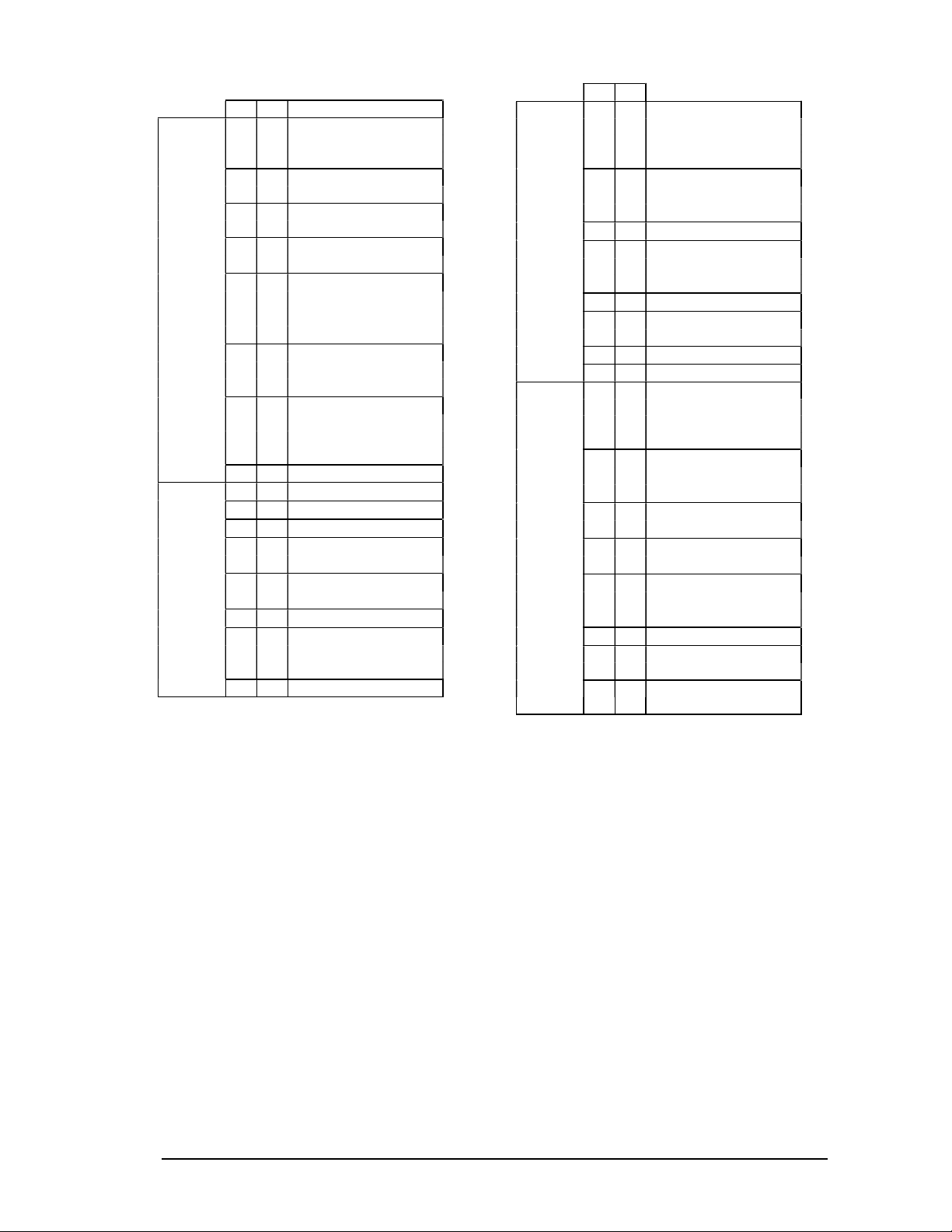
37
A B
1 0 Piano1
8 Piano 1w
16 Piano 1d
2 0 Piano 2
8 Piano 2w
3 0 Piano 3
8 Piano 3w
4 0 Honky-tonk
P
8 Honky-tonk w
5 0 E. Piano 1
I
8 Detuned EP1
16 E. Piano 1v
A
24 60'S E. Piano
6 0 E. Piano 12
N
8 Detuned EP2
16 E. Piano 2v
O
7 0 Harpsichord
8 Coupled Hps.
16 Harpsi. w
24 Harpsi o
8 0 Clav.
Chromatic
Percussion
9 0 Celesta
10 0 Glockenspiel
11 0 Music Box
12 0 Vibraphone
8 Vib. w
13 0 Marimba
8 Marimba w
14 0 Xylophone
15 0 Tubular-bell
8 Church Bell
9 Carillon
16 0 Santur
A B
17 0 Organ 1
8 Detuned Or. 1
16 60's Organ 1
32 Organ 4
18 0 Organ 2
O
8 Detuned Or. 2
32 Organ 5
R
19 0 Organ 3
20 0 Church Org. 1
G
8 Church Org. 2
16 Church Org. 3
A
21 0 Reed Organ
22 0 Accordian Fr
N
8 Accordian It
23 0 Harmonica
24 0 Bandoneon
25 0 Nylon-str. Gt.
8 Ukulele
16 Nylon Gt. o
32 Nylon Gt. o
26 0 Steel-str. Gt.
G
8 12-str. Gt.
16 Mandolin
U
27 0 Jazz Gt.
8 Hawaiian Gt.
I
28 0 Clean Gt.
8 Chorus Gt.
T
29 0 Muted Gt.
8 Funk Gt.
A
16 Funk Gt. 2
30 0 Overdrive Gt.
R
31 0 Distortion Gt.
8 Feedback Gt.
32 0 Gt. Harmonics
8 Gt. Feedback
Page 38
A B
33 0 Acoustic Bass
34 0 Fingered Bass
35 0 Picked Bass
36 0 Fretless Bass
37 0 Slap Bass 1
B
38 0 Slap Bass 2
39 0 Synth Bass 1
A
1 Synth Bass 101
8 Synth Bass 3
S
40 0 Synth Bass 2
8 Synth Bass 4
S
16 Rubber Bass
Strings/
Orchestra
41 0 Violin
8 Slow Violin
42 0 Viola
43 0 Cello
44 0 Contrabass
45 0 Tremelo Str
46 0 Pizzicato Str
47 0 Harp
48 0 Timpani
49 0 Strings
8 Orchestra
E
50 0 Slow Strings
N
51 0 Syn. Strings 1
S
8 Syn. Strings 3
E
52 0 Syn. Strings 2
M
53 0 Choir Aahs
B
32 Choir Aahs 2
L
54 0 Voice Oohs
E
55 0 Syn Vox
56 0 Orchestra Hit
A B
57 0 Trumpet
58 0 Trombone
1 Trombone 2
59 0 Tuba
60 0 Muted Trumpet
B
61 0 French Horn
R
1 French Horn 2
A
62 0 Brass 1
S
8 Brass 2
S
63 0 Synth Brass 1
8 Synth Brass 3
16 Analog Brass 1
64 0 Synth Brass 2
8 Synth Brass 4
16 Analog Brass 2
65 0 Soprano Sax
66 0 Alto Sax
67 0 Tenor Sax
R
68 0 Baritone Sax
E
69 0 Oboe
E
70 0 English Horn
D
71 0 Bassoon
72 0 Clarinet
73 0 Piccolo
74 0 Flute
75 0 Recorder
P
76 0 Pan Flute
I
77 0 Bottle Blow
P
78 0 Shakuhachi
E
79 0 Whistle
80 0 Ocarina
38
Page 39
A B
81 0 Square Wave
1 Square
8 Sine Wave
82 0 Saw Wave
Synth
Lead
1 Saw
8 Doctor Solo
83 0 Syn. Calliope
84 0 Chiffer Lead
85 0 Charang
86 0 Solo Vox
87 0 5th Saw Wave
88 0 Bass & Lead
89 0 Fantasia
90 0 Warm Pad
Synth
pad
etc.
91 0 Polysynth
92 0 Space Voice
93 0 Bowed Glass
94 0 Metal Pad
95 0 Halo Pad
96 0 Sweep Pad
97 0 Ice Rain
98 0 SoundTrack
99 0 Crystal
Synth
SFX
100 0 Atmosphere
101 0 Brightness
102 0 Goblin
103 0 Echo Drops
104 0 Star Theme
A B
105 0 Sitar
E
T
H
N
C
106 0 Banjo
107 0 Shamisan
108 0 Koto
8 Taisho Koto
109 0 Kalimba
I
110 0 Bag Pipe
111 0 Fiddle
112 0 Shanai
113 0 Tinkle Bell
P
E
R
C
U
S
S
V
E
114 0 Agogo
115 0 Steel Drums
116 0 Woodblock
8 Castanets
117 0 Taiko
8 Concert BD
118 0 Melo Tom 1
8 Melo Tom 2
I
119 0 Synth Drum
8 808 Tom
120 0 Reverse Cym.
121 0 Gt. Fret Noise
122 0 Breath Noise
123 0 Seashore
Sound
Effects
124 0 Bird
125 0 Telephone 1
126 0 Helicopter
127 0 Applause
128 0 Gun Shot
39
Page 40
General MIDI Level-1 Percussion Map
35. Ac Bass Dm 51. Ride Cym 1 67. Hi Agogo
36. Bass Dm 1 52. Chinese Cym 68. Lo Agogo
37. Side Stick 53. Ride Bell 69. Cabasa
38. Ac Snare 54. Tambourine 70. Maracas
39. Hand Clap 55. Splash Cym 71. Short Whistle
40. Elec Snare 56. Cowbell 72. Long Whistle
41. Lo Floor Tom 57. Crash Cym 2 73. Short Guiro
42. Closed Hi-Hat 58. Vibraslap 74. Long Guiro
43. Hi Floor Tom 59. Ride Cym 2 75. Claves
44. Pedal Hi-Hat 60. Hi bongo 76. Hi Woodblock
45. Lo Tom 61. Lo bongo 77. Lo Woodblock
46. Open Hi-Hat 62. Mute Hi Conga 78. Mute Cuica
47. Low-Mid Tom 63. Open Hi Conga 79. Open Cuica
48. Hi-Mid Tom 64. Lo Conga 80. Mute Triangle
49. Crash Cym 1 65. Hi Timbale 81. Open Triangle
50. Hi Tom 66. Lo Timbale
The SPEA MEDIA XTC also supports the
following extensions to the General MIDI
Percussion Map:
82. Shaker
83. Jingle Bell
84. Bell Tree
85. Castanets
86. Mute Suirdo
87. Open Suirdo
40
Page 41
MT-32 Sound Set
0. Accuo Piano 1 33. Harmo Pan 66. Elec Bass 1 99. Syn Mallet
1. Accuo Piano 2 34. Chorale 67. Elec Bass 2 100. Windbell
2. Accuo Piano 3 35. Glasses 68. Slap Bass 1 101. Glock
3. Elec Piano 1 36. Soundtrack 69. Slap Bass 2 102. Tube Bell
4. Elec Piano 2 37. Atmosphere 70. Fretless 1 103. Xylophone
5. Elec Piano 3 38. Warm Bell 71. Fretless 2 104. Marimba
6. Elec Piano 4 39. Funny Vox 72. Flute 1 105. Koto
7. Honkytonk 40. Echo Bell 73. Flute 2 106. Sho
8. Elec Org 1 41. Ice Rain 74. Piccolo 1 107. Shakuhachi
9. Elec Org 2 42. Oboe 2001 75. Piccolo 2 108. Whistle 1
10. Elec Org 3 43. Echo Pan 76. Recorder 109. Whistle 2
11. Elec Org 4 44. Doctor Solo 77. Pan Pipes 110. Bottleblow
12. Pipe Org 1 45. School Daze 78. Sax 1 111, Breathpipe
13. Pipe Org 2 46. Bellsinger 79. Sax 2 112. Timpani
14. Pipe Org 3 47. Square Wave 80. Sax 3 113. Melodic Tom
15. Accordian 48. Str Sect 1 81. Sax 4 114. Deep Snare
16. Harpsi 1 49. Str Sect 2 82. Clarinet 1 115. Elec Perc 1
17. Harpsi 2 50. Str Sect 3 83. Clarinet 2 116. Elec Perc 2
18. Harpsi 3 51. Pizzicato 84. Oboe 117. Taiko
19. Clavi 1 52. Violin 1 85. Engl. Horn 118. Taiko Rim
20. Clavi 2 53. Violin 2 86. Bassoon 119. Cymbal
21. Clavi 3 54. Cello 1 87. Harmonica 120. Castanets
22. Celesta 1 55. Cello 2 88. Trumpet 1 121. Triangle
23. Celesta 2 56. Contrabass 89. Trumpet 2 122. Orche Hit
24. Syn Brass 1 57. Harp 1 90. Trombone 1 123. Telephone
25. Syn Brass 2 58. Harp 2 91. Trombone 2 124. Bird Tweet
26. Syn Brass 3 59. Guitar 1 92. Fr Horn 1 125. One Note Jam
27. Syn Brass 4 60. Guitar 2 93. Fr Horn 2 126. Water Bell
28. Syn Bass 1 61. Elec Gtr 1 94. Tuba 127. Jungle Tune
29. Syn Bass 2 62. Elec Gtr 2 95. Brs Sect 1
30. Syn Bass 3 63. Sitar 96. Brs Sect 2
31. Syn Bass 4 64. Accou Bass 1 97. Vibe 1
32. Fantasy 65. Accou Bass 2 98. Vibe 2
41
Page 42

MT-32 Percussion Set
34. Drum Sound 51. Drum Sound 68. Drum Sound
35. _ _ _ 52. Accou High Tom 69. Low Timbale
36. Accou Bass Drum 53. Ride Cymbal 70. High Agogo
37. Accou Bass Drum 54. _ _ _ 71. Low Agogo
38. Rim Shot 55. _ _ _ 72. Cabasa
39. Accou Snare Drum 56. Tambourine 73. Short Whistle
40. Hand Clap 57. _ _ _ 74. Long Whistle
41 Elec Snare Drum 58. Cowbell
42. Accou Low Tom 59. _ _ _
43. Closed Hi-Hat 60. _ _ _
44. Accou Low Tom 61. _ _ _
45. Open Hi-Hat 2 62. High Bongo
46.Accou Middle Tom 63. Low Bongo
47. Open Hi-Hat 1 64. Mute High Conga
48. Accou Middle Tom 65. High Conga
49. Accou High Tom 66. Low Conga
50. Crash Cymbal 67. High Timbale
42
Page 43

Appendix B
Troubleshooting
If your SPEA MEDIA XTC card is not
functioning as it should, don't panic. The
problem is probably very simple to find and fix
as long as you remain calm and approach the
situation methodically.
The secret to troubleshooting is to examine the
evidence you have, gain as much information
as you can, and eliminate possibilities one by
one. In most cases, the source of the problem
will soon become clear.
For example, if the SPEA MEDIA XTC works
fine when you remove all other cards from your
computer, but it stops working when you
replace your fax-modem, a conflict between
the sound card and the fax-modem (such as
port address or IRQ ) may be indicated.
Often, problems are extremely simple; things
like bad cables, things not plugged in or turned
on, etc. Check the obvious first, not last.
Problems when Using Two
Sound Cards
Having another sound card in your system in
addition to the SPEA MEDIA XTC card will
greatly increase the chances of having system
conflicts. We highly recommend that any other
sound devices and their associated Windows
drivers be removed before installing the SPEA
MEDIA XTC card.
Configuration Problems
Adding new hardware and software to your
computer requires ensuring that there are no
conflicts with your existing system. If you have
difficulty with the installation procedure or are
unable to make the card work, a conflict may
be present. There are three major configuration
settings to consider: I/O Port Address, Interrupt
Request lines (IRQ), and Direct Memory
Access channels (DMA).
To resolve such conflicts, it is very important to
know the settings of other cards (it is best to
remove other sound cards) and peripherals
currently in your system, including the mouse,
fax-modem, video accelerators, etc.
One quick way to check for conflicts is to check
the configuration of all components in your PC
with the ICU Utility.
Boards without Plug & Play functionality have
to be enroled with the ICU Utility via the
corresponding CGF files or manually. Only
then can the ICU Utility distribute free
addresses for the Plug & Play boards like e.g.
the SPEA MEDIA XTC.
Audio Problems
If you are satisfied that the SPEA MEDIA XTC
hardware and software are properly installed
with no conflicts, but you hear no sound at all,
the problem may be with your audio
connections. Here are some suggestions:
Try playing both a .WAV file and a .MID file
to ascertain that there is no sound at all
coming from the speakers. If you hear one
and not the other, the problem is internal
and has nothing to do with your audio
system.
Be sure that your stereo system is properly
set up. Try connecting a sound source other
than SPEA MEDIA XTC, such as an audio
CD player, and establishing whether or not
you can hear it.
Be sure that the sound card is properly
connected to the monitoring system (a 1/8"
mini-phone cable should be running from
the SPEA MEDIA XTC Out connector to a
line input on the monitoring system). To
eliminate the possibility of a bad cable, try
plugging a pair of high-impedance
headphones (such as most Walkman-type
phones) to the SPEA MEDIA XTC Out jack
and see if you hear any sound.
Problems Internal to the SPEA
MEDIA XTC
If you suspect that the problem is internal, the
computer or the card may have become
'confused', which is generally simple to
remedy.
Run the SSInit program to reinitialize the
board.
Open the mixer in SSInit or Audiostation
and move the faders to make sure that the
mixer values aren't set to zero.
Initialize the card without changing any
settings. To do this, run SSINIT with a
specific mode argument (i.e., SSINIT GM,
SSINIT MT32, or SSINIT FM). Entering
SSINIT with no specific mode argument will
take you into the configuration screens
discussed in Part 3 in this manual.
In general, it is good practice to reset the
computer (power off-on or 'warm' reboot by
pressing CTRL+ALT+DEL) after changing
port, DMA, or IRQ settings.
43
Page 44

Problems with Games
Problems under Windows
Make sure that the SPEA MEDIA XTC is in
the proper operating mode. One way to be
sure is to follow the guidelines for choosing
the proper mode in Part 4 of this manual,
section Using SPEA MEDIA XTC with
Games.
If the game's Install or Setup program
doesn't give you a particular sound option
that you know the game supports, (e.g., the
game's box and manual specify MT-32, but
the game's Install or Setup doesn't support
it), try rerunning the game's Install or Setup
program after first initializing the sound card
to the particular mode. Some 'smart' install
programs try to auto-detect your sound
card, and if the SPEA MEDIA XTC is set to
the wrong mode, the Install program may
not recognize it.
If you select a game mode and the game's
Install program says something like 'Sound
card not found, proceed anyway?', choose
'yes'. In some cases, you can still install the
program and it will work fine. The problem
lies in the way some install programs check
for the presence of sound cards.
If you are having difficulty with the playback
of Sound Blaster digital audio emulation,
there could be an IRQ conflict with your
selection for SB IRQ/Wave IRQ in SSInit.
One possible cause is that IRQ 7, which is
used automatically by many games for
digital audio, is being used by your LPT1
port. Try setting your SB IRQ/Wave IRQ in
SSInit to 5 (Remember not to set the SB
IRQ/ Wave IRQ to the same value as your
IRQ under Base Values).
It is a good practice to initialize SPEA
MEDIA XTC before playing each game
(See Part 4).
If you are having a problem with your
external game/joystick controller, make sure
that the SPEA MEDIA XTC joystick is
disabled. This should solve the problem. Do
this in the SSInit Hardware Settings screen.
In order to use two joysticks, you will need
to use a Sound Blaster compatible Yconnector, or use an industry-standard MIDI
Joystick kit. This will make allowances for
the proper direct connections for dual
joysticks.
If you are able to run Windows, but the
SPEA MEDIA XTC software applications
don't work, it is likely that your Windows
device drivers are not functioning properly.
This is the first place where you should look
for problems. It is also the first thing you
should look at when running the sound card
under Windows for the first time. See Part
3, section Configuring SPEA MEDIA XTC
Under Windows for information on
configuring and troubleshooting the
Windows device drivers using the Driver
Setup screen.
If digital audio playback is consistently
repeating, then your Primary Wave Interrupt
assignment is probably incorrect. Go to the
Driver Setup screen and look at the Status
Line.
If digital audio playback is intermittently bad
then you probably have a DMA conflict in
your machine. Go to the Driver Setup
screen and try a different DMA channel.
Next, you must edit the SYSTEM.INI file in the
Windows directory to find and remove any
virtual device drivers that are in conflict with
your SPEA MEDIA XTC device drivers. To do
this, locate the section of the file under the
[386Enh] header. Look for 'device=*.386'
entries, where * is the device driver name, and
remove any entries that correspond to other
sound cards' virtual MIDI or DMA device
drivers.
Examples of such entries would be:
device=vmqxd.386 (Music Quest virtual MPU401 [MIDI] device driver)
device=vsbd.386 (Sound Blaster virtual DMA
device driver)
Be careful not to remove the following:
device=*vdmad (Microsoft virtual DMA driver)
device=vtdapi.386 (Microsoft virtual timer
driver)
device=vvdmad.386 (SPEA MEDIA XTC virtual
DMA driver)
Use the SPEA MEDIA XTC UNINSTALL
Utility to remove the SPEA MEDIA XTC
components from your system. Then
reinstall the SPEA MEDIA XTC software.
See 'Uninstalling the SPEA MEDIA XTC
Software' in the Addendum of the SPEA
MEDIA XTC manual
If all else fails, try restoring your original
SYSTEM.INI file (backed up as
SYSTEM.SND), then reinstalling the SPEA
MEDIA XTC Software.
44
Page 45

Problems with MIDI under
Windows
If you are able to play and record .WAV files
with no problem, but are experiencing difficulty
getting the synthesizer or MIDI functions to
work, try the following.
Check the MIDI Mapper and make sure that
MIDI data is being directed where you want
it to go (remember that the SPEA MEDIA
XTC MIDI Out device will bypass the SPEA
MEDIA XTC synthesizer and will instead
drive only the external MIDI port). If the
MIDI Mapper icon does not appear in the
Control Panel, it means that your MIDI
drivers are not properly installed. In this
case, open the Drivers applet (in the
Windows Control Panel) and install the MIDI
Mapper driver.
If you are trying to use MIDI Out to drive an
external MIDI device, be sure:
a) that the channels are properly assigned in
the MIDI Mapper;
b) that a genuine MIDI cable (not just any
cable with 5-pin DIN connectors) is
connecting the SPEA MEDIA XTC MIDI Out
to the external device's MIDI In; and
c) that the channel, mode, and sound of the
external device are properly set up.
Take note that the 'In' and 'Out' labeling on
the MIDI adapters refers to MIDI 'In' and
'Out' on your sound card and not the
external device. Therefore, the cable
labeled 'In' should go to the MIDI connector
labeled 'Out' on your external synthesizer,
and the cable labeled 'Out' should go to the
connector labeled 'In' on your external
synthesizer.
Confirm that you are using the proper
adapter for the Joystick/MIDI port.
If you are playing MIDI data into the SPEA
MEDIA XTC but you aren't hearing
anything, it is likely that the software you are
using needs to be set to echo the
information back out to a sound device. You
can accomplish this by turning on a feature
in the Windows appli-cation called MIDI
Thru or MIDI Merge. This function will take
any incoming MIDI data and echo it back
out to the MIDI Mapper. In this instance,
make sure your MIDI Mapper setup is
sending MIDI data to the device which you
are trying to hear.
45
Page 46

Appendix C
Technical
Specifications
On-board Processor
8 MHz Motorola 68EC000
Synthesizer
Architecture: Digital Wavetable Synthesis
Voices: Up to 32
Polyphony: Up to 32 notes
Sample Memory: 1 Mbyte of ROM, 4 MB
compressed sound
D/A Converter: 16-bit Linear Serial
Playback Sample Rate: 31.250 kHz
Level and Panning Controls: Separate
12-bit L&R controls for each voice
Filters: Separate Configurable 4-Pole Digital
Filter for each voice
Envelopes: Hardware Envelopes for Ampli-tude
and Filters
Mic/Line Input
Connector 3.5 mm (1/8") mini phone jack
Tip = signal
Sleeve = Ground
Nominal Input Level: 100 mV r.m.s. (70 mV pp) in Mic mode, 1 V r.m.s. (700 mV p-p) in Line
mode
Nominal Input Impedence: 100 kOhms
CD/Aux Input
Connector: 3.5 mm (1/8") mini phone jack
Tip = L channel
Ring = R channel
Sleeve = Ground
Max Input Level: 1 V r.m.s. (2.8 V p-p)
Nominal Input Impedence: 22 kOhms
TV Tuner Input
Connector: Pin header
Max Input Level: 1 V r.m.s. (2.8 V p-p)
Nominal Input Impedence: 22 kOhms
Modem Input
Connector: Pin header
Max Input Level: 1 V r.m.s. (2.8 V p-p)
Nominal Input Impedence: 22 kOhms
Audio Output
Connector: 3.5 mm (1/8") mini phone jack
Tip = L channel
Ring = R channel
Sleeve = Ground
Max Output Level into a Line Input: 2 V r.m.s.
(5.6 V p-p)
Max Output Level into Headphones: 100mW
into Hi-Z headphones (Walkman Style)
PCM Playback Section
Devices: One Wave output (playback) devices
and one Wave input (record) device.
Capability: Simultaneous playback of single
mono or streams while recording a single
mono or stereo stream.
D/A Converter: 16-bit Linear Serial SigmaDelta Converter
Max Playback Sample Rate: 48.0 kHz
Level and Panning Controls: Separate
12-bit L&R controls for each voice
Formats: 8-bit unsigned linear, 8-bit u-law and
a-law, 16-bit signed linear. All formats Mono or
Interleaved Stereo.
Digital Recording Section
A/D Converter: 16-Bit Linear Serial SigmaDelta Converter
Available Sampling Rates: 5.5125, 6.615, 8.0,
9.6, 11.025, 16.0, 18.9, 22.05, 27.42857, 32.0,
33.075, 37.8, 44.1, and 48.0 kHz
Source Selection: Any external source,
microphone, CD, Synthesizer, TV Tuner,
Modem or wave
Level Control: Individual
Level Control Range: 0 to -38 dB on all other
record sources
Formats: 8-bit unsigned linear, 8-bit u-law and
a-law, 16-bit signed linear. All formats Mono or
Interleaved Stereo.
46
Page 47

47
Audio Mixing
Input Sources: Synthesizer Output, PCM
Output, CD/Aux Input , Mic/Line Input, TV
Tuner, Modem
Level Control: 12-bit for Synthesizer and PCM,
5-bit for all others
Level Control Range: 0 to -62 dB for all
Frequency Response: 20-20,000 Hz ± 1 dB
Distortion: <0.5%
Signal/Noise Ratio: >80 dB
Host Interface
Configuration: 68B50 Communications
Interface, MPU-401 MIDI Interface. Emulation
of MPU-401 or 68B50 UART-based MIDI
Interface
Number of Ports: 4
Base Port Address: 330-33F, 350-35F (Plug &
Play)
Interrupt Usage: 2/9, 5, 7, 10; up to two
possible, software selectable
DMA Usage: 0, 1, 3, 5, 6; up to five possible,
Plug & Play
Number of MIDI Ports: 1 In, 1 Out/Thru (using
Optional Expander Cable)
Software Features: MIDI Split, Merge, and
Time Stamp
MIDI Clock: 12-bit, 1 MHz Counter with
Synchronized Tempo Updates
Joystick Interface: Standard PC-Compatible
Joystick Port
Max Number of Joysticks: 2 (2 Axis, 2 Buttons)
or 1 (4 Axis, 4 Buttons)
MIDI/Joystick Connector
1 +5V
2 Joystick A button 1 +
3 Joystick A X-coordinate
4 GND (Joystick A buttons 1 & 2 -)
5 GND (Joystick B buttons 1 & 2 -)
6 Joystick A Y-coordinate
7 Joystick A button 2 +
8 +5V
9 +5V
10 Joystick B button 1 +
11 Joystick B X-coordinate
12 MIDI Out
13 Joystick B Y-coordinate
14 Joystick B button 2 +
15 MIDI In
Page 48
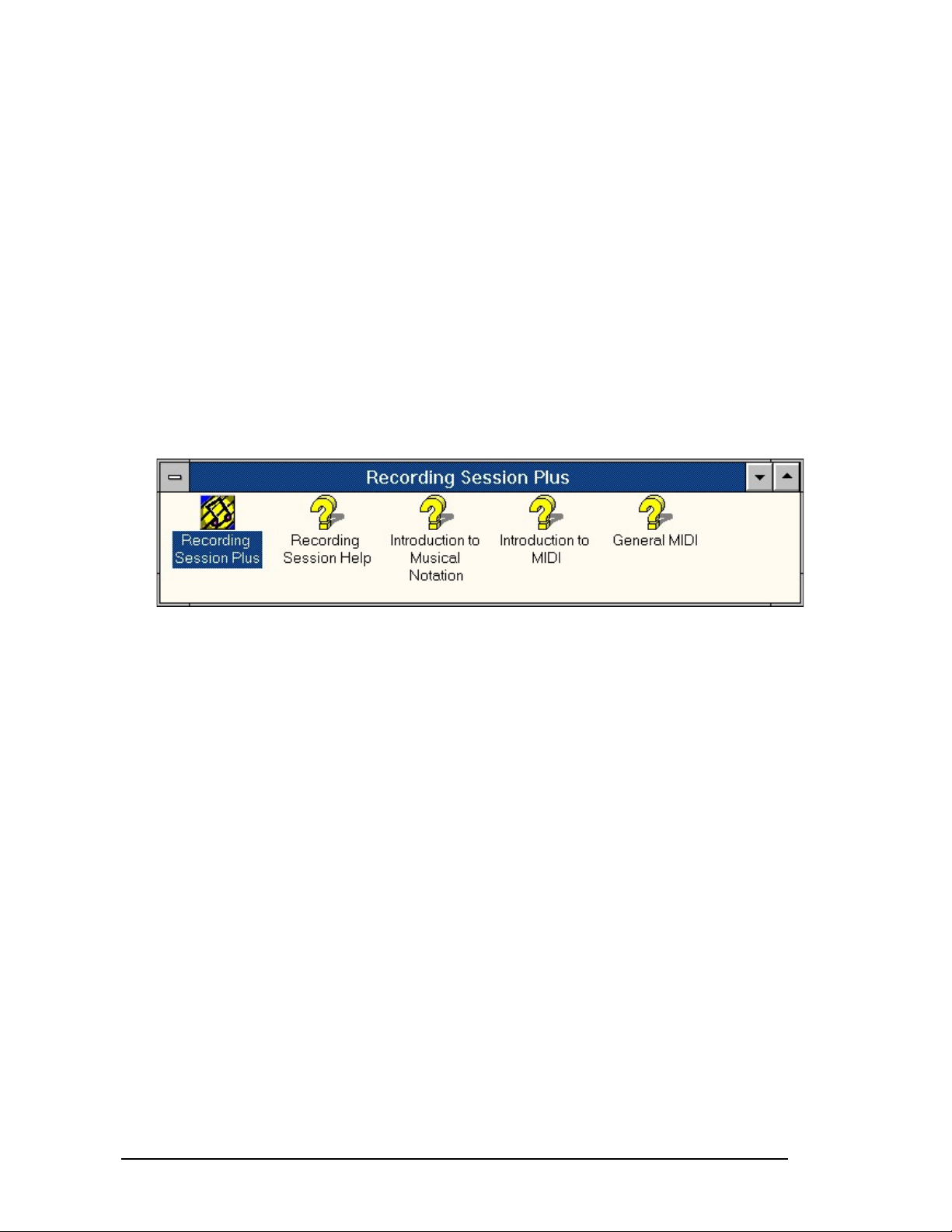
Appendix D
MIDISOFT Recording
Session Plus
MIDISOFT's Program Recording Session Plus
is a powerful sequencer offering Standard MIDI
sequencing features, as well as an editable
musical notation display.
When you have successfully installed the
software, you will find detailed online help
information about notation, MIDI and General
MIDI as well as about the Program Recording
Session Plus itself so that you will find it very
easy to use the Program.
How to install the Software:
1. Insert the MIDISOFT Installation disk in the
corresponding disk drive.
2. Start Windows (if not already done)
3. Start the Installation from the Program
Manager with the following call:
'File' 'Run'
A:\SETUP.EXE
4. Follow the instructions on the screen.
The program will be installed onto your hard
disk.
After you have successfully installed the
software you will find the program group
'Recording Session Plus' with the program and
the online help as mentioned above.
48
Page 49

Appendix E
Glossary
ASCII: American Standards Committee on
Information Interchange. A standard used by
PC-compatible computers to represent
numbers and characters in binary form.
AUTOEXEC.BAT: A batch file that directs the
activities performed by the computer during
system startup, including a good deal of setup
and configuration.
BIOS: Stands for Basic Input-Output System.
Code in your computer’s ROM (Read Only
Memory) that provides the power-on, self test
and other operating functions.
Booting/Booting Up: Starting the computer.
There are two types. Warm Booting is
accomplished by simultaneously pressing the
CTRL/ALT/DEL keys (or by pressing your
computer’s RESET button) and can occur only
when the computer is running. A cold boot
requires activation of the ON/OFF switch.
CONFIG.SYS: An ASCII file that is created to
provide the computer with special information
about applications and hardware.
DMA: Direct Memory Access. A facility that
allows a peripheral to access system memory
without having to involve the CPU.
Driver: A small program that performs as the
software interface between a peripheral (i.e.,
video and sound card, printer, keyboard, etc.)
and the host (main) computer. Drivers are
often loaded as specified by CONFIG.SYS
when the system is booted up.
Expansion Card: An internal peripheral, added
to expand a computer’s capability. The SPEA
MEDIA XTC is an expansion card.
Expansion Slot: The physical space and
accompanying connectors within the computer
where expansion cards are installed.
FM Synthesis: A method of synthesizing
sound, popularized by Yamaha and used by
most early sound cards, that is based on
Frequency Modulation.
General MIDI: An extension to the MIDI
specification that defines a minimum set of
standards for a class of instrument known as a
'General MIDI Instrument'. These standards
include correlation between MIDI program
change numbers and types of instrument
sounds. See also MIDI.
49
Page 50

I/O Port: Input/Output port. Computers typically
use a memory address to communicate with a
peripheral via an I/O port. Knowing and
accessing the specific address and port for a
given peripheral is usually the job of the driver.
See also Driver.
.INI File: An ASCII text file that specifies
default values and configuration variables for a
program. An .INI file is read and used when the
program is booted.
Interrupt Request (IRQ): Signal used by a
device, such as a mouse, to inform the
computer that it is in need of attention.
Jumper: A small plastic plug that fits over a
pair of pins. When the cap or plug straddles
two pins, it makes an electrical connection. The
computer makes decisions based on whether
the connection is made or not. A group of
jumper pins is called a jumper block.
.MID file: The Windows format for Standard
MIDI Files. See also Standard MIDI File.
MIDI: A specification, consisting of both
hardware and software components, that
allows a wide variety of music synthesizers,
audio equipment, and other entertainmentrelated devices to communicate with each
other.
MPU-401: A popular PC MIDI interface
protocol developed by Roland Corp.
MT-32: A popular sound module manufactured
by Roland Corp whose sound set became
somewhat of a standard in sound cards. The
MT-32 was a primary catalyst for the adoption
of General MIDI.
Multimedia: The integration of numerous
audio and visual media, such as graphics,
animations, sound recordings, MIDI data, etc.,
in the pre-sentation of a work.
OPL-2/OPL-3: Two generations of FM
synthesis chips produced by Yamaha and
made popular in early sound cards.
Peripheral Equipment: Auxiliary equipment
connected to a computer (e.g., sound card,
monitor, printer, keyboard, etc.). A peripheral
may reside inside or outside the computer.
50
Page 51

RAM: Random Access Memory; memory that
can be read from and written to. In common
usage, RAM refers to the internal, volatile
memory used by the computer to hold
programs and data while it is working with
them. Information stored in RAM is lost if
power is removed
ROM: Read Only Memory; memory space in
your computer for storing permanent operating
instructions. Information stored in ROM is
retained even if power is removed
.SND files: A DOS file format for storing digital
audio recordings.
Sound Blaster: A popular early sound card.
Many games assume the presence of a Sound
Blaster. The SPEA MEDIA XTC is fully Sound
Blaster compatible.
Standard MIDI File: An addition to MIDI
specification that defines a standard file format
for MIDI sequences.
SYSTEM.INI: A configuration file executed
when Windows is booted. It is used primarily to
load device drivers into memory.
Terminate and Stay Resident (TSR):
Programs that remain in memory after being
run in order to make it easy to reactivate them.
TSRs may use substantial memory and cause
conflicts with other programs.
.WAV files: The standard Windows file format
for digital audio recordings.
Wavetable Synthesis: A type of synthesis
based on playing back short samples of actual
instruments. Since it uses recordings of actual
instruments, wavetable synthesis sounds more
realistic than FM.
WIN.INI: A file specifying how Windows should
be configured when it is booted.
51
 Loading...