

Page 1
SPEA CRUNCH IT
User Manual
Benutzerhandbuch
Manuel d'emploi
Manual del usuario
Part Number 1740 4040.3
Rel. 0695
Copyright by SPEA Software AG
Page 2

2 3
Page 3

Copyright 1995 SPEA
The information furnished in this manual is believed to be accurate and reliable. However, SPEA
assumes no responsibility for its use; nor for any infringements of patents or other rights of third parties
which may result from its use.
SPEA reserves the right to change the specifications of the products described in this manual in the
interests of technical progress at any time without notice. No part of this document may be reproduced
by any means, nor translated to any medium without prior, written consent from SPEA.
The installation program used to install the SPEA Superdisk, INSTALL, is based on the licensed
software provided by Knowledge Dynamics Corp., Highway Contract 4, Box
185-H, Canyon Lake, Texas 78133-3508 (USA), 1-512-964-3994.
Knowledge Dynamics Corp. reserves all international copyright and protection rights. The INSTALL
program is provided for the exclusive purpose of installing the SPEA Superdisk.
SPEA has made modifications to the software as provided by Knowledge Dynamics Corp., and thus
the performance and behaviour of the INSTALL program supplied with the SPEA Superdisk may not
represent that of INSTALL as supplied by Knowledge Dynamics.
SPEA is exclusively responsible for the support of the SPEA Superdisk, including the support for the
installation. SPEA is reponsible for the technical support.
1995 SPEA Software AG. All rights reserved.
Registered Trademarks
IBM PC and PC-DOS are registered trademarks of International Business Machines Corporation.
MS-DOS is a registered trademark of Microsoft Corporation.
MultiSync is a registered trademark of NEC Corp.
PCI and PCI Local Bus are registered trademarks of the PCI Special Interest Group (SIG).
VESA is a registered trademark of the Video Electronics Standards Association.
Windows is a registered trademark of Microsoft Corporation.
All other names are tradenames / trademarks of their respective owners.
FCC Compliance
This board has been tested and found to comply with the limits for a Class B digital device, persuant to
Part 15 of the FCC Rules. These limits are designed to provide reasonable protection against harmful
interference in residential installation. This device generates, uses and can radiate radio frequency
energy and, if not installed and used in accordance with the instructions, may cause harmful
interference to radio communications. However, there is no guarantee that interference will not occur in
a particular installation.
Installing the Software from the SPEA Media-Gallery CD
It is possible that you have received the SPEA software on CD rather than on diskette. If this is the
case, then please note that the descriptions in this manual should be changed accordingly. For
example, the instructions "Put the disk 'Drivers for Windows' in drive A:" would be exchanged with the
following steps: "Switch to the CD drive (e.g. D:) and enter the path of the desired driver, e.g.
D:\SPEA\INSTALL\MERCURY.P64\WIN
for the Windows driver for the V7-MERCURY P-64 board.
Other subdirectories could be 'DOS&UTIL' (for utilities and DOS tools) and 'OS2' (for OS/2 driver
software).
Important Note
You must imperatively read the README file on your 'Utilities' disk and all the documentation supplied
with your graphics board before installing it! If you fail to do so SPEA can not accept any responsibility
for claims that may be caused as a consequence.
To see the README file, put the 'Utilities' disk in your floppy drive and type:
A:
SHOW README.ENG
Page 4

Table of Contents
QUICK INSTALLATION...........................................................................................................................6
GENERAL INFORMATION...................................................................................................................... 7
Guide to this Manual .............................................................................................................................7
Symbols and Conventions.....................................................................................................................7
Delivery Scope Checklist.......................................................................................................................7
Last-Minute Changes - README file....................................................................................................8
Warranty................................................................................................................................................8
Support..................................................................................................................................................8
Company Address.................................................................................................................................8
PART 1 INTRODUCTION .......................................................................................................................9
What is the SPEA CRUNCH IT and what is it used for?.......................................................................9
Features of the SPEA CRUNCH IT .......................................................................................................9
Software for your Board ........................................................................................................................9
PART 2 HARDWARE INSTALLATION.................................................................................................. 10
Installation of the board...........................................................................................................................10
System Requirements and Considerations.........................................................................................10
Typical System Configuration..............................................................................................................10
Preparing the Installation.....................................................................................................................11
Installing the SPEA Card.....................................................................................................................11
Connecting External Equipment..........................................................................................................12
Installation of the SPEA CRUNCH IT (Stand alone) ...........................................................................13
Installation of the SPEA CRUNCH IT with the SPEA SHOWTIME PLUS ..........................................14
Installation SPEA CRUNCH IT with a Soundboard (V7-media fx) ......................................................15
After Installing the SPEA Board ..........................................................................................................16
Tips and Tricks for installing the SPEA CRUNCH IT..........................................................................16
PART 3 WINDOWS 3.X DRIVER INSTALLATION AND CONFIGURATION .......................................17
Software Configuration of the SPEA CRUNCH IT under Windows ....................................................18
If you use the SPEA CRUNCH IT together with a SPEA SHOWTIME PLUS.....................................18
The SPEA CRUNCH IT driver dialogues ............................................................................................18
Video Format.......................................................................................................................................19
Video Source.......................................................................................................................................21
Video Display ......................................................................................................................................22
PART 4 WINDOWS 95 DRIVER INSTALLATION AND CONFIGURATION........................................ 23
PART 5 VIDEO MAESTRO....................................................................................................................23
VideoMaestro Programs .........................................................................................................................23
Video Capture .....................................................................................................................................23
Video Editor.........................................................................................................................................23
Video Morph........................................................................................................................................24
Video Logo Generator.........................................................................................................................24
Video Screen Saver ............................................................................................................................24
Media File Finder.................................................................................................................................24
Samples..................................................................................................................................................24
MediaMaestro Demo Software ...............................................................................................................25
System Requirements ............................................................................................................................27
User Registration ................................................................................................................................27
Technical Support ...............................................................................................................................27
User's Guide - Online Help .....................................................................................................................27
Copyright Notice..................................................................................................................................27
VideoMaestro Getting Started.................................................................................................................28
Video Editor.........................................................................................................................................28
Creating a Video with the Video Editor................................................................................................28
Creating a Simple Video Clip ..............................................................................................................28
Creating a Complex Video ..................................................................................................................29
4
Page 5

Video Morph............................................................................................................................................31
Creating a Morph Video ......................................................................................................................31
Video Logo Generator.............................................................................................................................32
Creating a Video Logo.........................................................................................................................32
Creating a Rotating Logo ....................................................................................................................33
A Multiple Rotating Logo with a Background Image............................................................................34
APPENDIX A UTILITIES ........................................................................................................................37
CRUNCH IT INIT - Protecting the Video Monitor and TV from damaging Signals .............................37
Test- / Diagnostics program ................................................................................................................37
APPENDIX B TECHNICAL DETAILS....................................................................................................38
Technical Data........................................................................................................................................38
Pinout of the SPEA Movie Bus ...............................................................................................................38
I/O Addresses of the SPEA CRUNCH IT................................................................................................39
IRQ setting of the SPEA CRUNCH IT ....................................................................................................39
The Connections of the SPEA CRUNCH IT ...........................................................................................39
APPENDIX C TROUBLESHOOTING ....................................................................................................40
General Considerations ..........................................................................................................................40
Hardware settings ...............................................................................................................................40
Configuration Problems with PCI Motherboards.....................................................................................40
Frequently Asked Questions...................................................................................................................41
General problems................................................................................................................................41
Problems with Windows ......................................................................................................................41
Problems with the Playback and Editing of Video Sequences............................................................41
APPENDIX D GLOSSARY.....................................................................................................................43
INDEX .....................................................................................................................................................53
5
Page 6

Quick Installation
This Quick installation is for experienced users only! Other readers should
take the time to read the manual.
1. Make a backup copy of the disks supplied with the board.
2. Check that your monitor and system configuration support the SPEA card
(e.g. correct bus type and version).
3. Disconnect your computer from the main power and peripheral equipment.
4. Install the SPEA CRUNCH IT in a free extension slot and secure it.
5. Reassemble your PC, connect peripheral equipment and reconnect the
power cable.
6. Connect peripheral equipment (e.g. video recorder, video monitor) to the
video in and out connections of the SPEA CRUNCH IT.
7. Switch on your monitor first, then the computer.
8. Insert the SPEA installation disk and start the software installation under
Windows with the following entry:
A:
SETUP
(Warning! If you have additionally installed a SPEA SHOWTIME PLUS in
your system, run the software installation of this board BEFORE you install
the SPEA CRUNCH IT).
9. Install the additional video editting software.
Problems?
In the unlikely event of problems ...
1. Check the README file on the SPEA Installation disk #1, the Media Gallery
CD or after the installation the directory C:\SPEA\CRUNCHIT.
2. Read Appendix C: Troubleshooting.
3. If you have installation and application problems with your SPEA graphics
board you can obtain technical support via the SPEA Support Mailbox.
4. Take note of your warranty - see section Introduction.
5. Contact the SPEA ExpertLine (see last pages in this manual)
Warning!
Your board is a complex electronic device and can only be repaired by
authorized technical personnel with the required equipment. Do not attempt to
change or repair any parts of this product. Doing so will render your warranty
invalid.
6
Page 7

General Information
Guide to this Manual
This manual is divided into five parts:
Part 1 Introduction
Part 2 Tells you how to physically
install the graphics board.
Part 3-5 Provides information for
installing the application
drivers included on the
SPEA Superdisk or Media
Gallery CD.
Appendices Contain other information
that you should review.
Index To enable you to find
subjects in this manual
quickly.
Symbols and Conventions
The following symbols and syntax conventions
are used in this manual:
Warning!
This section contains a warning or important
information.
Note: This section contains useful hints.
DOS commands are written in capital letters,
example:
A:
INSTALL
If not defined in another way, all DOS
commands must be confirmed with the ENTER
or RETURN key.
Example: Examples are indicated by this
format.
Screen messages are shown in Courier.
References to other parts of the manual are
shown in italic.
Directory names mentioned in this manual are
examples and are written in capital letters.
The SPEA software is delivered on 3,5" disks.
Therefore, the documentation refers to disk
drive A:. Please enter B:, if your 3,5" disk drive
is addressed with B:.
- this manual
- 'Pixel Shrink' manual
Delivery Scope Checklist
Your SPEA package should contain the
following items:
- 1 SPEA CRUNCH IT board
- 1 SPEA Movie Bus connection cable
- the following 3.5" disks:
2 SPEA Installation disks
3 disks (or 1 CD) 'Video Maestro'
(Software Dynamics)
2 disks 'PixelShrink' (CeQuadrat)
7
Page 8

Last-Minute Changes - README file
Our software is constantly being improved and
updated. The latest information is contained in
a file named README. It appears on the
screen automatically at the end of the software
installation. You can also read this file at any
time from your hard disk (after the installation)
with the command:
SHOW README
or from your diskette with:
A:
SHOW README.ENG
Warranty
You have a 3 year warranty for your SPEA
graphics card. To ensure your warranty, it is
necessary that you keep the invoice of the
graphics card. If your graphics card is
damaged, contact your local retailer first.
Your board is a complex electronic device and
can only be repaired by authorized technical
personnel with the required equipment. Do not
attempt to change or repair any parts of this
product. Doing so will render your warranty
invalid.
Support
The following support services are offered by
SPEA Software AG:
technical support (telephone, SPEA
ExpertLine)
online information and software updates per
modem (SPEA Mailbox)
software updates on CD via the SPEA
Media Gallery CD.
Further information concerning these support
services can be found in the 'SPEA ExpertLine'
section on the last pages of this manual.
Company Address
SPEA Software AG
Moostr. 18B
D-82319 Starnberg
Tel: +49 81 51 26 60
Fax: +49 81 51 21 258
8
Page 9

Part 1
Introduction
What is the SPEA CRUNCH IT and
what is it used for?
The SPEA CRUNCH IT enables you to transfer
videos from your video recorder to your PC and
vice versa. You have the possibility to edit the
transferred video material on your PC. With the
delivered video software, you can cut video
sequences, define titles and add a soundtrack
to the video and transfer it back to the video
recorder. With the corresponding image
processing programs, multimedia databases
and presentation programs a.s.o. you can reuse the video material.
Features of the SPEA CRUNCH IT
ZORAN ZR 36050/055 Motion JPEG
Controller
Real time and True Colour digitizing in YUV
format
frame format adjustable from 320 x 240
pixels up to 768 x 576 pixels
Software for your Board
The standard software delivery scope of the
SPEA CRUNCH IT contains the following
programs:
Menu driven installation program to easily
install the software
Software drivers for Windows and Video for
Windows
Utilities for the configuration
Video Software
Video Maestro (Software Dynamics)
PixelShrink (CeQuadrat)
digitizing in full frame rate, 50 fields (25
frames) for PAL and SECAM and 60 fields
(30 frames) for NTSC
ISA bus board, can be combined with any
VGA board
Video Input : (video recorder, laser disk or
camcorder in PAL, NTSC or SECAM
format)
- 2 Composite Video in
- 1 Y/C (S-VHS, Hi-8) Video in
Video Output (for video monitoring while
digitizing and outputting the M-JPEG
sequences on video):
- 1 Composite Video Output
- 1 Y/C (S-VHS, Hi-8) Video Output
SPEA Movie Bus (YUV Bus) for transferring
the video data to the multimedia boards
SPEA SHOWTIME PLUS or SPEA PLAY IT
variable compression rates from 1:5 up to
1:100 with full resolution
correction of brightness, contrast, colours
a.s.o.
Check the glossary in this manual for a brief
description of the abbreviations used here.
9
Page 10

Part 2
Hardware Installation
Installation of the board
System Requirements and
Considerations
IBM compatible computer (486/586) with a
free ISA bus expansion slot
MS-DOS operating system MS-DOS or PCDOS, version 5.0 or later
8 MB RAM
Hard disk capacity
about 100 MB free disk space,
ideally defragmented;
(recommended: 1 GigaByte or more)
Transmission rate (write / read) under
Windows ca. 400 Kbyte/s;
(recommended: at least 1 MB/s)
32 Bit Hard disk driver (Enhanced IDE or
SCSI)
(recommended: hard disk with AV (Audio /
Video) firmware)
Graphics Board and Monitor
256 colours
(recommended: High - or TrueColour)
640 x 480 pixels
(recommended: 800 x 600 or 1024 x 768
pixels)
Video In
Video source such as a video recorder, video
camera a.s.o.)
Video Out
Output device, e.g. video monitor or video
recorder + video monitor
Audio
Windows compatible soundboard, if sound
should be edited.
Typical System Configuration
A typical configuration environment for your
board is described as follows:
Tower 486DX4, 100 MHz, PCI bus (better:
Pentium), 16 MB
SPEA 2185 MS Monitor
Video source: video recorder or video
camera
Video output: video monitor or video
recorder
Windows compatible soundboard - if sound
should be edited
Double speed CD ROM drive
Warning
Prevent damage by static electricity. Static
electricity can cause severe damage to
microcircuits, but here are some easy ways to
see that it doesn't happen.
1. Hold the SPEA card on ist edges only. Don't
touch edge connectors or exposed circuitry.
2. Leave the SPEA card in the anti-static
protective bag until ready to install it in your
computer.
3. If possible, ground your body when handling
the SPEA card. The metal power supply
housing is generally considered the best
place to ground yourself.
4. Do not place the SPEA card on a metal
surface.
5. Make the least possible movement to avoid
building up static electricity from your
clothing, carpets and furniture.
!
10
Page 11
Preparing the Installation
Warning!
Please note that, before you install the SPEA
CRUNCH IT, a VGA board or multimedia board
(e.g. SPEA SHOWTIME PLUS (see the section
after the next one) has to be installed and
configured in your system. Start the installation
of the SPEA CRUNCH IT after you have
installed the VGA or multimedia board.
Additional information can be found in the
manual of the corresponding board.
1. Switch off your computer and all external
options (printer, display and others) and
unplug all power cords from the electrical
source.
2. Remove the cover mounting screws and
save them for later.
3. Remove the cover of the computer.
Installing the SPEA Card
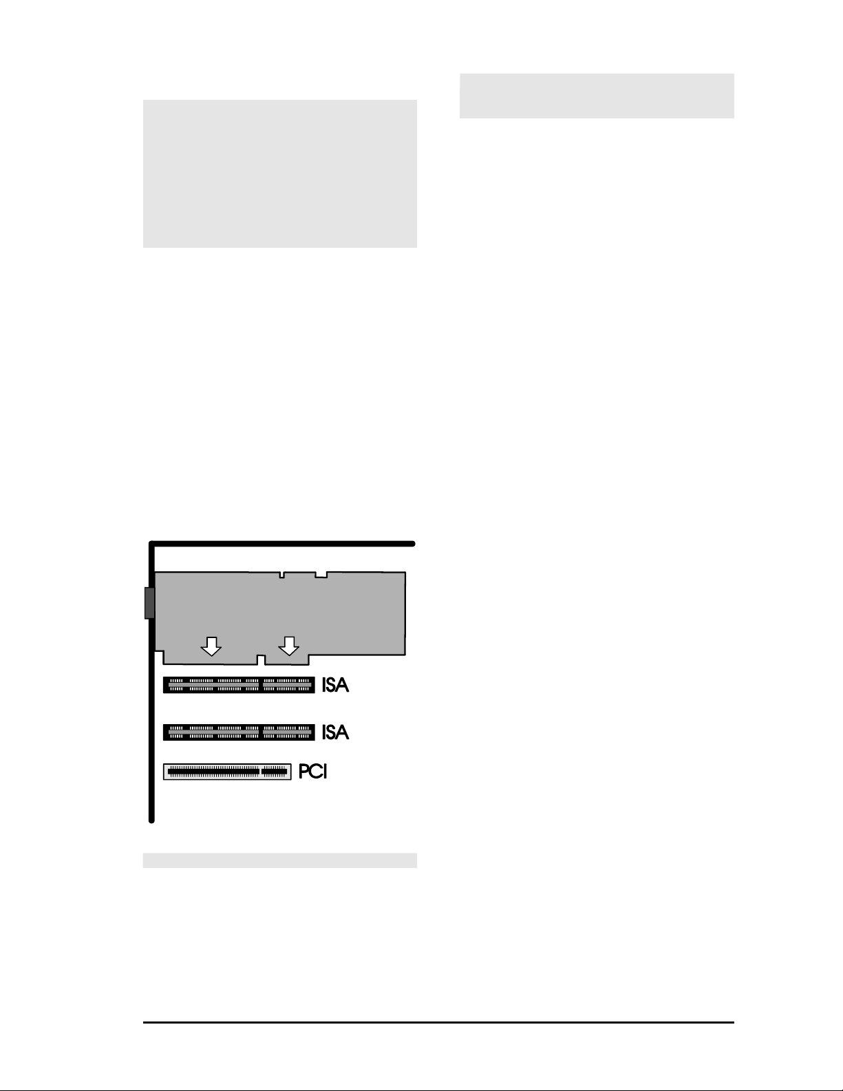
The SPEA card is installed in a free ISA bus
expansion slot .
1. Select a free expansion slot and remove its
metal slot cover. Save the screw to secure
the graphics card later.
2. Hold the card by the edges and press it
firmly into the expansion slot.
Warning!
The following step is very important in order to
ground your SPEA card properly.
3. Align the slot in the mounting bracket of the
SPEA card with the screw hole in the rear
panel of the computer case. Use the screw
you removed from the expansion slot cover
or the previously installed video adapter to
secure the SPEA card in place.
4. Install the multimedia board - if necessary e.g. the SPEA SHOWTIME PLUS or a
Windows compatible Soundboard (e.g. V7media fx; see the corresponding manual) in
your system.
5. This step is only valid for the SPEA
SHOWTIME PLUS:
Connect the SPEA Movie Bus of both
boards with the SPEA Movie Bus
connection cable supplied with the SPEA
CRUNCH IT. Secure the cable on the SPEA
Movie Bus so that the red stripe is
positioned at pin #1 on both boards (see
also the diagram on page 10 of this
manual).
6. As soon as you have installed all boards
(VGA board or SPEA SHOWTIME PLUS,
SPEA CRUNCH IT and possibly a
soundboard) in the system, secure ribbon
cables and gently push them down and out
of the way before you replace the system
cover.
7. Fix and secure the system cover on the PC
again.
8. Reconnect any peripheral equipment cables
you may have disconnected.
Read the next sections to see how to proceed
with connecting the peripheral devices.
Installing the Card in an ISA Slot
11
Page 12
Connecting External Equipment
The connectors on the board are standardized,
with the exception of the SPEA Movie Bus (see
Appendix B, Technical Details). For this
reason, you only need to take note of a few
points when making connections to external
equipment.
Warning!
Be sure to connect any peripheral devices to
the computer and switch them on BEFORE
switching on your computer. This avoids a
damaging power surge, and the possibility of
electrical discharge damage when live
connections meet.
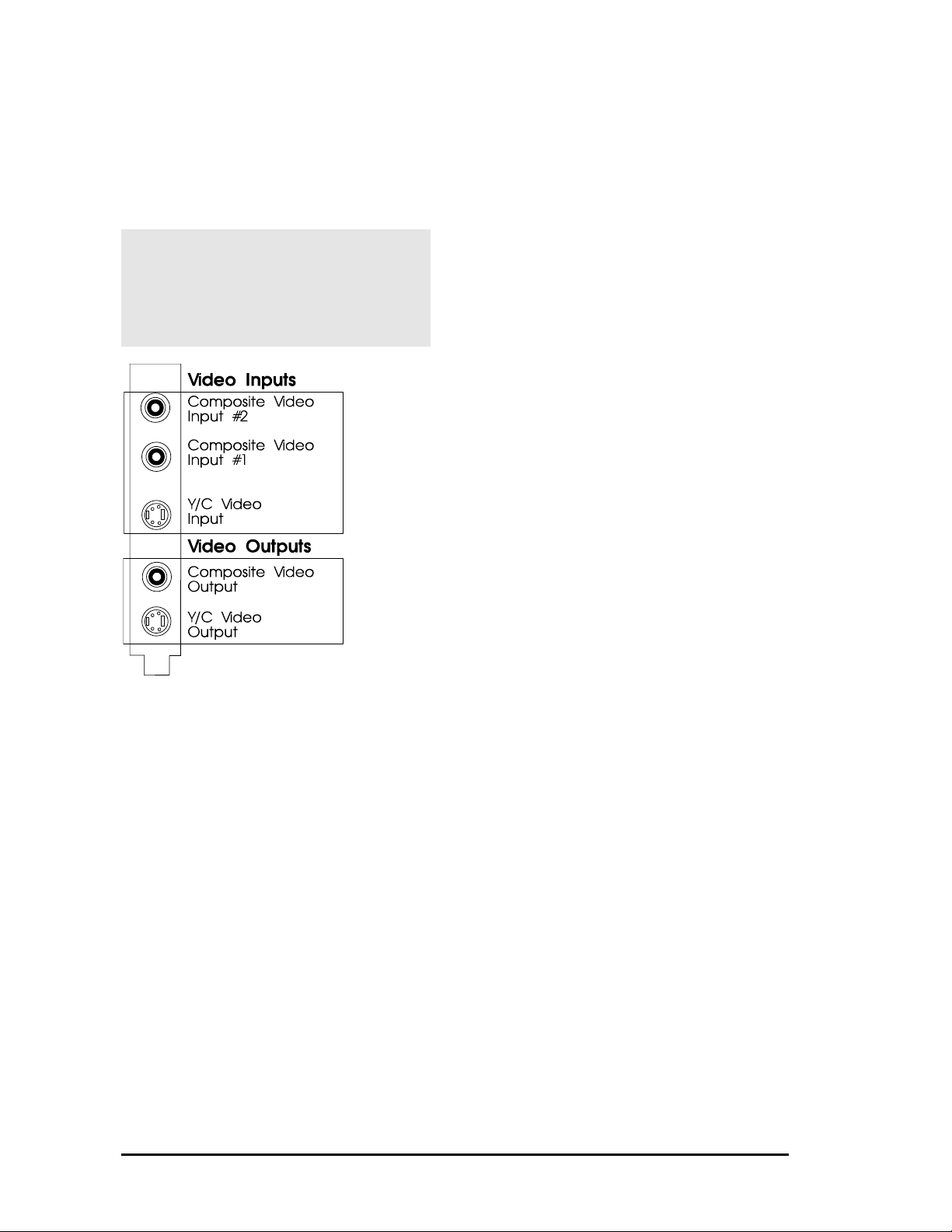
Composite Video In
This can be connected to a video source
such as a video recorder or a video camera.
Note that the antenna signal from the
wall socket is not suitable!
Y/C Video In for S-VHS video or Hi-8:
Use this input if your video device offers this
connection (e.g. a S-VHS or Hi-8 video
recorder). You'll attain better picture quality.
Composite Video Output:
For connecting a controlling monitor or a
video recorder.
Y/C (S-VHS, Hi-8) Video Output:
For connecting a S-VHS or Hi-8 video
recorder.
SPEA Movie Bus
This connector is intended for use with
SPEA products, e.g. SPEA SHOWTIME
PLUS of SPEA PLAY IT. This is NOT a
Feature Connector.
In the next three sections, three different
operating modes of the SPEA CRUNCH IT are
described and illustrated.
Inputs and Outputs of the SPEA CRUNCH IT
12
Page 13
Installation of the SPEA CRUNCH IT
(Stand alone)
If you want to use the SPEA CRUNCH IT
without an additional board (multimedia
board or soundboard), please note that
BEFORE you install and run the SPEA
CRUNCH IT, a VGA graphics board must
either be installed or already integrated
in your system.
If you install the SPEA CRUNCH IT
without a SPEA SHOWTIME PLUS or a
SPEA PLAY IT, you will need (in addition
to your VGA monitor) a video monitor to
check the video image. This is
necessary, because the SPEA CRUNCH
IT doesn't use overlay technology and
on the PC only a blank window can be
seen under Video for Windows. If you
work with video editing software under
Windows without a video monitor, you
can use the preview function, because
this feature is software driven. While
capturing, only frames (no video) will be
displayed.
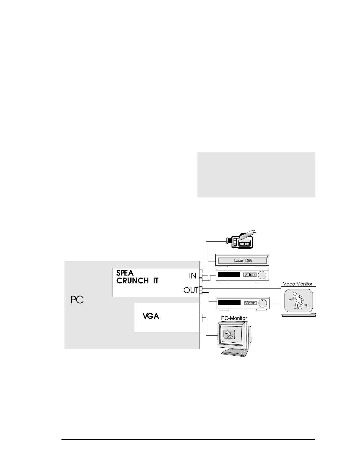
After both boards (the VGA board and SPEA
CRUNCH IT) are installed in your system,
connect the peripheral equipment as follows:
1. Connect the PC monitor cable with the VGA
output of the VGA board.
2. Connect your video source to the
corresponding video input connection of the
SPEA CRUNCH IT.
3. Connect your video output device to the
corresponding video output connection
(video recorder and monitor) - either
separate or the video monitor and the video
recorder coupled together.
Note:
Always combine two similar connections, Y/C
(S-VHS or Hi-8) with Y/C, and Composite with
Composite!
Warning!
Be sure to connect any peripheral devices to
the computer and switch them on BEFORE
switching on your computer. This avoids a
damaging power surge, and the possibility of
electrical discharge damage when live
connections meet.
Configuration SPEA CRUNCH IT as a stand alone system
13
Page 14
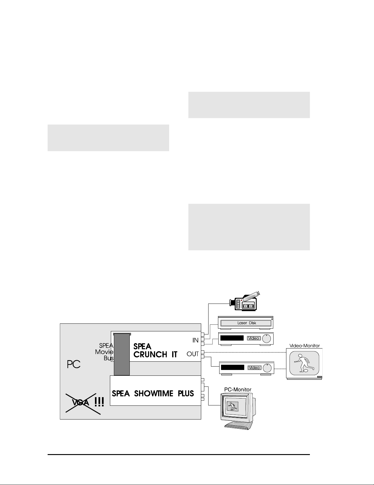
Installation of the SPEA CRUNCH IT
with the SPEA SHOWTIME PLUS
There are several possibilities to connect the
SPEA CRUNCH IT with external devices. The
following example shows a configuration which
allows you to use the additional functionality of
a multimedia board.
In this operating mode the video image is
inserted via the SPEA SHOWTIME PLUS in a
window on the PC monitor. In this case a video
monitor is not strictly necessary.
Warning!
If you use two activated VGA boards in your
PC at the same time you may damage your
system!
When you use the SPEA CRUNCH IT together
with a SPEA SHOWTIME PLUS, please
remove any other VGA boards from the system
or deactivate VGA parts that are integrated on
the motherboard.
After both boards (VGA and SPEA CRUNCH
IT) are installed in your system, connect the
peripheral equipment as follows:
1. Connect the PC monitor cable to the VGA
output of the VGA board.
2. Connect your video source to one of the
video input connections of the SPEA
CRUNCH IT.
Warning!
As soon as you have installed the drivers of the
SPEA CRUNCH IT, the video input of the
SPEA SHOWTIME PLUS will be disabled!
3. Optional (not necessary for video editting):
Connect your video output device to one of
the video output connections (video
recorder and monitor) - either separately or
with the video monitor and the video
recorder coupled together
Note:
Always combine two similar connections, Y/C
(S-VHS or Hi-8) with Y/C and Composite with
Composite!
Warning!
Be sure to connect any peripheral devices to
the computer and switch them on BEFORE
switching on your computer. This avoids a
damaging power surge, and the possibility of
electrical discharge damage when live
connections meet.
Note for the Software Installation:
Install the software of the SPEA SHOWTIME
PLUS FIRST, then the software of the SPEA
CRUNCH IT!
Configuration SPEA CRUNCH IT with SPEA SHOWTIME PLUS
14
Page 15
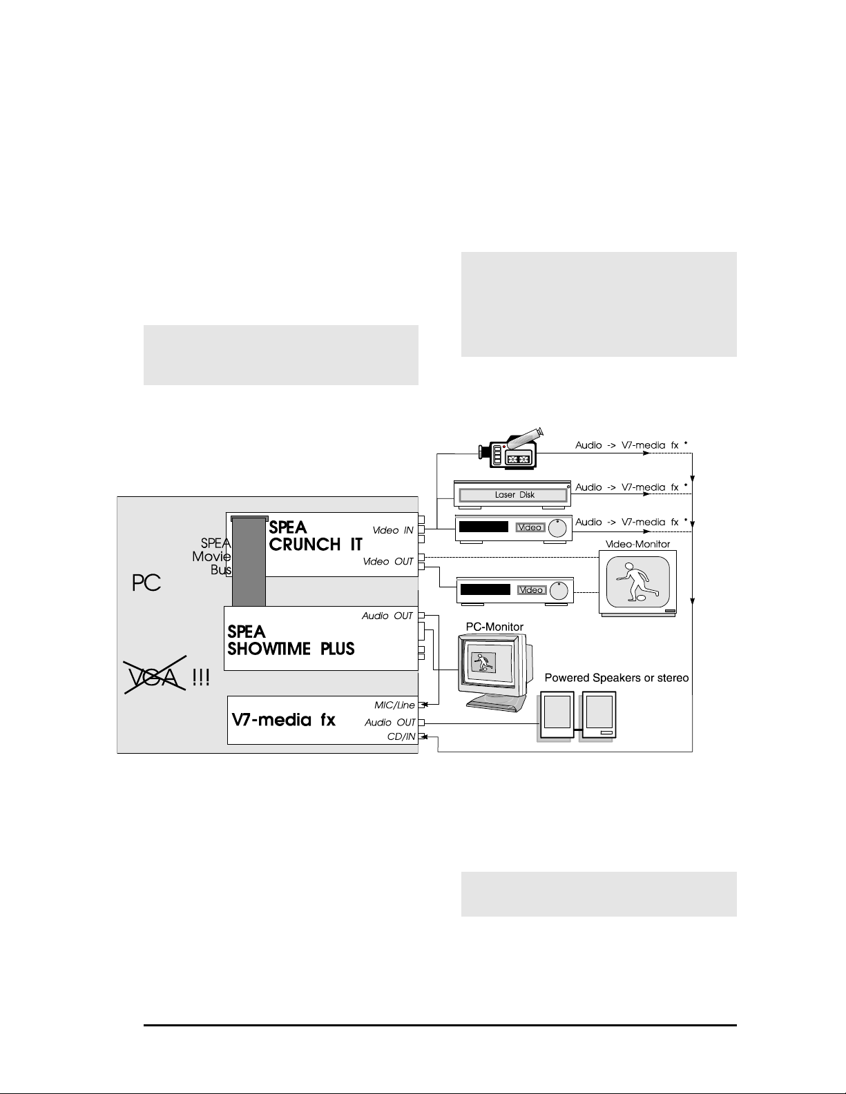
Installation SPEA CRUNCH IT with a
Soundboard (V7-media fx)
It is necessary to install a Windows compatible
soundboard (e.g. SPEA's V7-media fx) if you
also want to edit the sound of your video.
Instead of a SPEA SHOWTIME PLUS, you can
also use a graphics board (whereby there is no
audio connection between the soundboard and
the graphics board).
After all boards are installed in your system,
connect the peripheral equipment as follows:
1. Connect your video source and output
devices as described in the previous
section.
Warning!
As soon as you have installed the drivers of the
SPEA CRUNCH IT, the video input of the
SPEA SHOWTIME PLUS will be disabled!
2. Connect the audio output of the SPEA
SHOWTIME PLUS with the audio input of
the V7-media fx.
3. Connect the audio output of the video
source with the audio input of the V7-media
fx.
Note:
Always combine two similar connections, Y/C
(S-VHS or Hi-8) with Y/C, and Composite with
Composite!
Warning!
Be sure to connect any peripheral devices to
the computer and switch them on BEFORE
switching on your computer. This avoids a
damaging power surge, and the possibility of
electrical discharge damage when live
connections meet.
Note for the Software Installation:
Install the software of the SPEA SHOWTIME
PLUS FIRST, then the software of the SPEA
Configuration SPEA CRUNCH IT with the V7-media fx
CRUNCH IT!
* In order to play sound alternately from various
audio sources it is advisable to use a mixer.
Warning!
Avoid feedback! (loud whistling noise). This
can damage your devices and loudspeakers!
15
Page 16

After Installing the SPEA Board
If you have correctly installed the SPEA board,
the DOS prompt will appear on your monitor
when the boot procedure is finished.
If your system does NOT boot as it should,
check again to see that the installation
instructions were properly followed, or refer to
Appendix C (Troubleshooting).
Tips and Tricks for installing the
SPEA CRUNCH IT
Defragment your Hard Disk
You can speed up your work if you defragment
your hard disk (with the DOS 6.x command
DEFRAG) before you begin.
Zone Bit Recording (ZBR)
Modern hard disks record less sectors on the
inner tracks (=Zone Bit Recording) than on the
outside tracks. Because a disk is filled from the
outside to the inside, it will get slower the more
it is filled.
Deactivate the Cache Function
If the 'Write Caching' function is activated, the
continous dataflow to the hard disk can be
interrupted.
Deactivate the 'Write Caching' or switch it off
completely. Windows works very slowly with a
deactivated cache. It is advisable to reorganize
your hard disk into two partitions and to
deactivate the cache function for the partition
which will contain the stored video sequences.
In some cases (not always) it makes sense to
deactivate the read cache for the drive which is
used for storing the video sequences. This
depends on your individual system configuration. A generalisation is not possible.
Install a permanent swap file
Install a permanent swap file under Windows.
This will improve your performance under
Windows and the Windows applications used,
e.g. the video editing software, Video Maestro.
What you should consider if you buy a new
Hard Disk
Check that the hard disk has a fast access
time and (much more important) that the data
transmission rate is as high as possible. If you
look for the data transmission rate, be sure
not to confuse the data for the interface speed
(E-IDE 16 MB/s or SCSI 10 MB/s), with the
actual transmission rate of the hard disk. A
new hard disk should have a data rate of 1,0
MB/s. SCSI hard disks normally are faster than
IDE hard disks.
It is very important that a 32 bit driver (.386)
for Windows is available for the hard disk (EIDE) or the SCSI host adapter used, otherwise
Windows will not be capable of using the high
speed of the hard disk.
It is advisable to use a special Audio / Video
(AV) hard disk. These hard disks guarantee a
high data rate without interrupts.
You will find more information in the
README.ENG file on the installation disk.
Keep it simple to begin with
Although it may be tempting when installing the
SPEA CRUNCH IT to connect your
soundboard, SPEA SHOWTIME PLUS, video
source a.s.o., it is wise not to try to do
everything at once. Make sure your VGA board
or multimedia board is installed correctly and
works properly. The same applies to your
soundbard - if installed in your PC.
Make the connections properly
If just one cable is not connected correctly, the
flow of data will be broken and one or more
parts of your multimedia system will not work
properly. As many of the standard cables are
very similar, it is possible to make a mistake.
VHS versus S-VHS
VHS video tapes can be played back with a
S-VHS recorder, but vice versa there is no
possibility to playback a S-VHS video tape with
a VHS recorder.
S-VHS delivers significantly superior quality.
16
Page 17

Part 3
Windows 3.x
Driver Installation and
Configuration
Notes for the Software Installation:
If you have also installed a SPEA
SHOWTIME PLUS is your system, run
this software installation BEFORE you
install the software for the SPEA
CRUNCH IT!
You must have already installed
Windows on your system!
Before installing the supplied software,
make a backup of the SPEA installation
disks. Use the backup copy for your
installation and store the originals in a
safe place.
1. Start Windows and insert the SPEA
CRUNCH IT installation disk in drive A:.
2. In the Program Manager select 'File'
'Run' and enter the following command in
the dialog box:
A:
SETUP
3. Follow the instructions on the screen. The
necessary drivers for the SPEA CRUNCH
IT will be installed onto your system.
4. Next, restart your system so that the
changes take effect.
Note:
If you have problems with the installation with a
PCI system, you can find more information in
Appendix C: Troubleshooting in this manual.
Before you start to edit video captures on your
PC you have to configure the SPEA CRUNCH
IT under Windows as described on the next
page.
17
Page 18
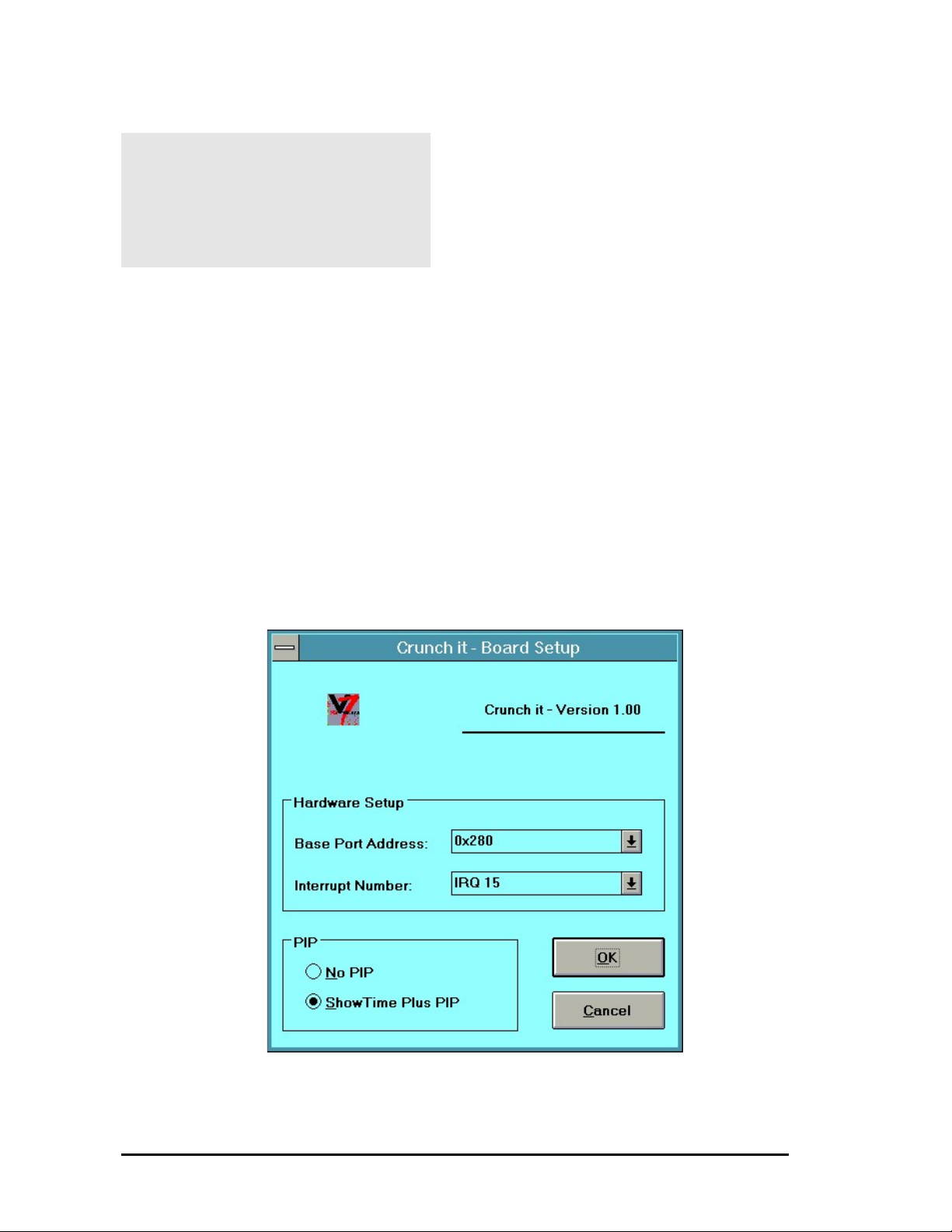
Software Configuration of the SPEA
CRUNCH IT under Windows
Warning!
During the driver configuration, or when you
start the video editting software system,
software crashes may occur if there is no video
signal present at the video input of the SPEA
CRUNCH IT.
In this case terminate Windows, activate a
video signal and then restart Windows.
1. In the Program Manager's Main Group open
the Icon 'Control Panel' .
2. Select the option 'Driver'.
3. In the dialogue box doubleclick on either of
the following drivers:
'Crunch it-Motion JPEG Capture driver'
'Crunch it-Motion JPEG CoDec driver'
You will find yourself in the Board Setup
Dialogue. Here you can change the base
address and the interrupt number if, the SPEA
CRUNCH IT doesn't work properly.
The default settings are:
Base=0x280 / Int=15.
If you use the SPEA CRUNCH IT
together with a SPEA SHOWTIME
PLUS
If you use the SPEA CRUNCH IT in
combination with a SPEA SHOWTIME PLUS,
you should switch the dialogue 'PIP' from 'No
PIP' to 'Showtime Plus PIP'. This activates the
SPEA Movie Bus which makes it possible to
see an overlay image of the currently edited
video image using video software.
If a SPEA SHOWTIME PLUS is not installed in
your system, or if you want to remove it, switch
(back) to 'No PIP' to communicate this to the
driver.
The SPEA CRUNCH IT driver
dialogues
You will have access to the following dialogue
boxes when you have installed and configured
these drivers and use them within a video
edition software such as Video Maestro or
Adobe Premiere.
Therefore it is necessary that you have
installed the software completely. The driver
dialgoues appear when you have selected the
corresponding configuration option from within
the software package.
18
Page 19
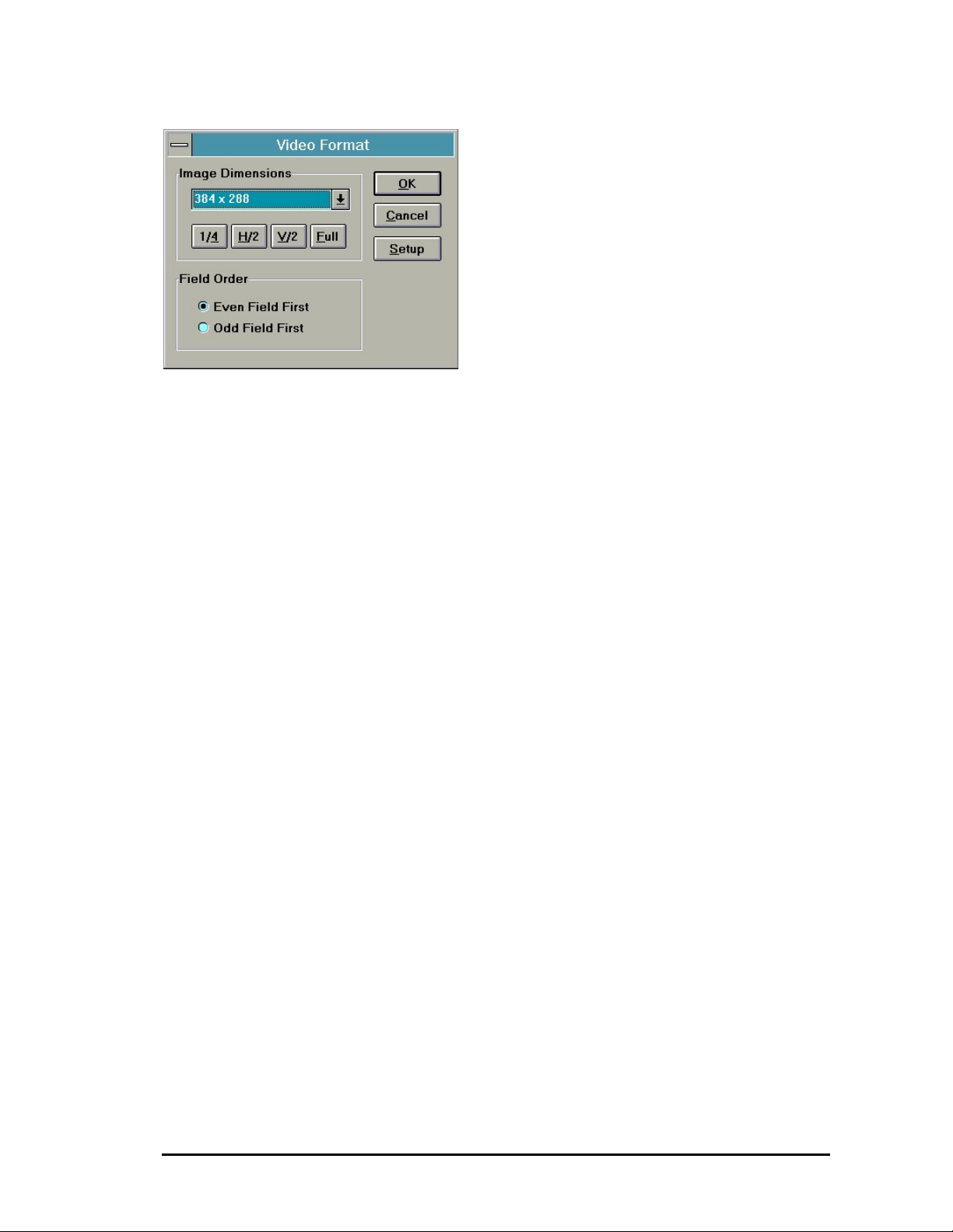
Video Format
Image Dimensions
Defines the resolution which you want to use
for digitizing. Depending on the video standard
set, you will have the following resolutions:
1/4 PAL: 384 x 288 pixels,
NTSC: 320 x 240 pixels,
these resolutions are also called SIF
(Source Image Format).
With this setting, the digitized frame will
be scaled by half on the x - axis. Only
every second field will be processed,
that means: PAL 25 fps, NTSC 30 fps
H/2 PAL: 384 x 576 pixels,
NTSC: 320 x 480 pixels; in comparison
to the 1/4 mode, both fields are
processed, that means:PAL: 50 fps,
NTSC 60 fps
V/2 PAL: 768 x 288 pixels, NTSC 640 x
240 pixels, only each second frame is
processed in full horizontal resolution
Full PAL: 768 x 576 pixels, NTSC: 640 x
480 pixels; here the full video frame is
used. Both fields are processed in full
resolution.
19
Page 20
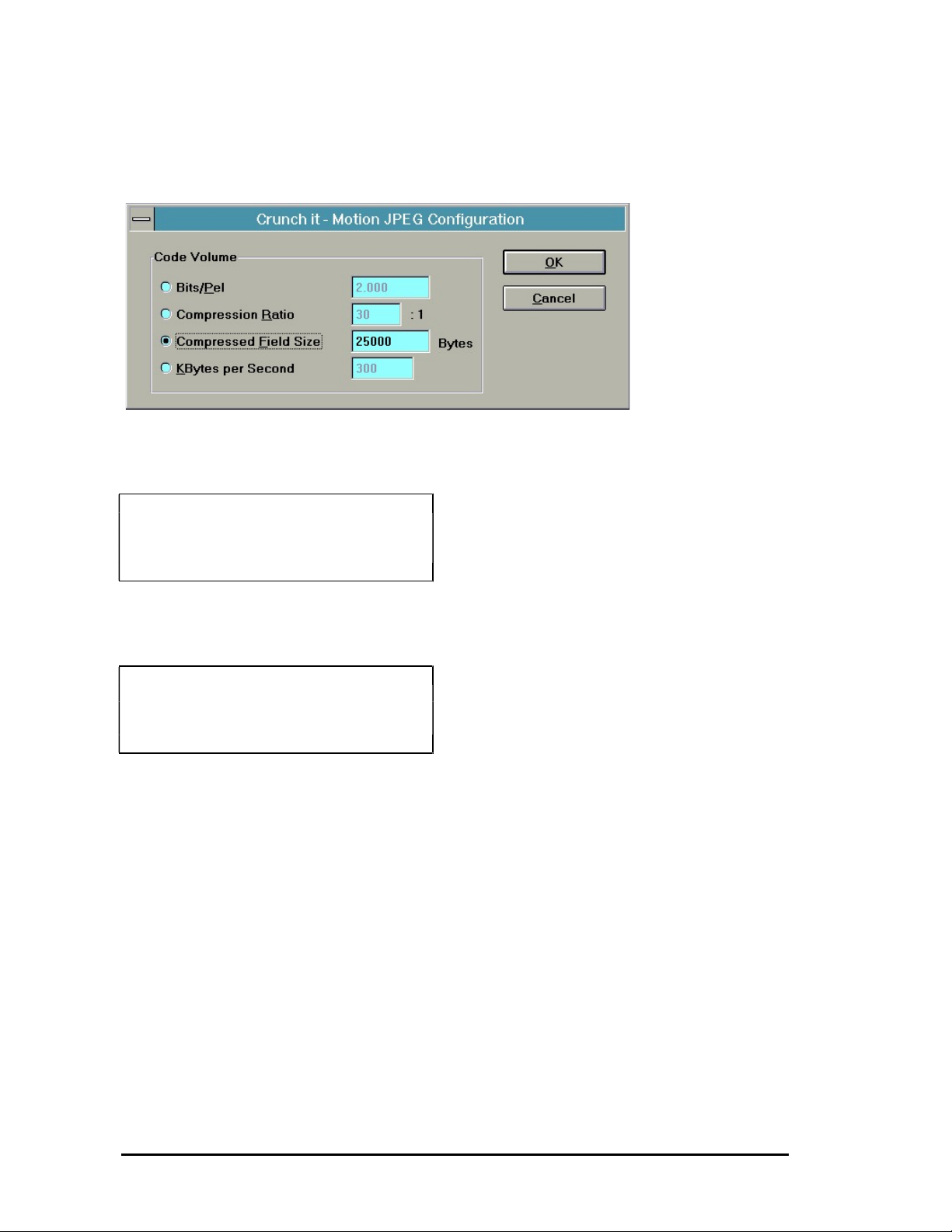
Setup.Code Volume
Defines the compression rate:
Note:
Only one setting at once is active. All options
have an influence on the compression rate.
Bits/Pel [2.0]
Bits per Pixel element (dynamic compression
rate)
Example:
Frame resolution x (Bits/Pel / 8)=
Size of the compressed frame
384 x 288 x (2.0 /8) = 27648 = 27kB
Compression Ratio [24]:1
Compression rate in the following ratio:
Data volume compressed frame / original data
Example:
Frame resolution x 2 x (1/Ratio) =
Size of the compressed frame
384 x 288 x 2 x(1/24) = 9216 = 9 kB
Compressed Frame Size [20000] Bytes
Shows the size of a compressed single frame
in Bytes.
KB per second [300]
Shows the resulting amount of data in KB/s.
The setting assumes 25 (PAL) or 30 (NTSC)
fps (frames per second).
20
Page 21
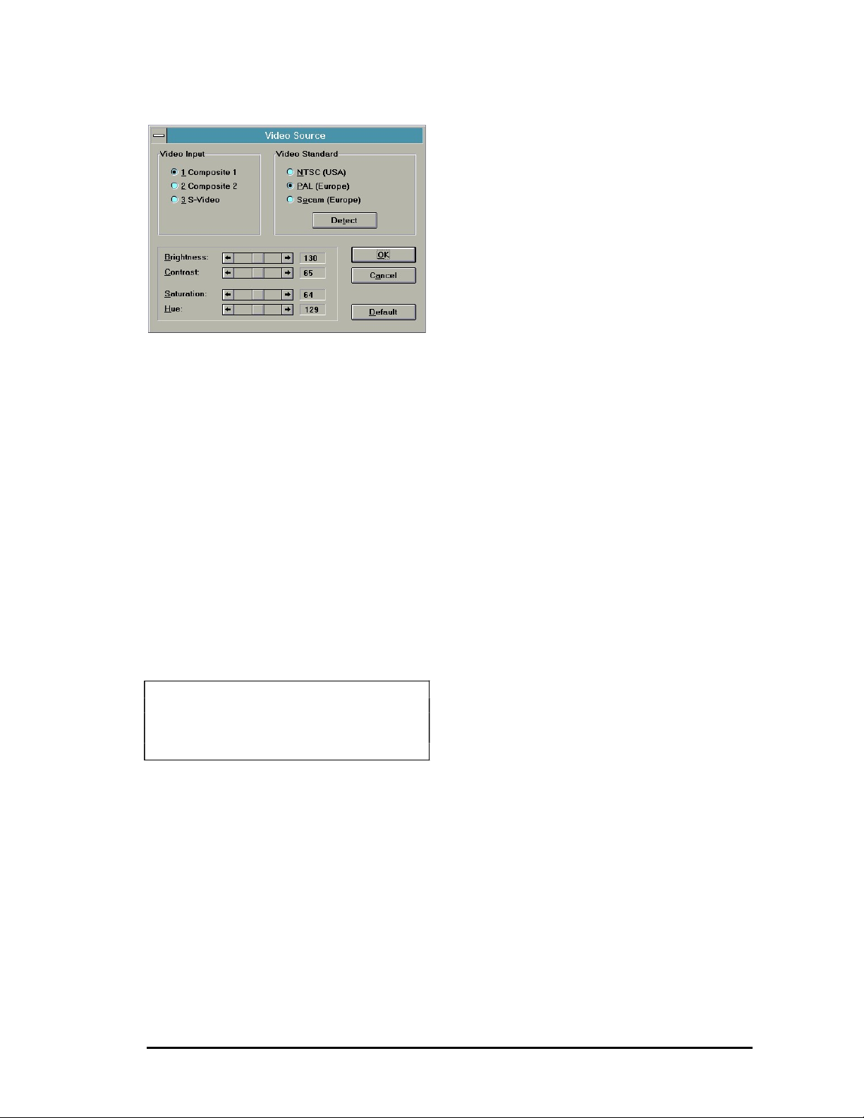
Video Source
Video Input
Selects one of the video inputs
- Composite 1 (Video Input #1)
- Composite 2 (Video Input #2)
- S-Video (Y/C Input)
Video Standard
- NTSC (USA) {60 Hz}
- PAL (Europe) {50 Hz}
- SECAM (Europe) {50 Hz., e.g. France}
- Detect discovers which of the three standard
video signals is sent to the selected video
input.
Video Control
The following settings correct the specific
parameter during the digitizing process:
Brightness: controls the light content
Contrast: controls the contrast
Saturation: controls the color saturation
Hue: controls the colors
Default setting:
Video Input: 1
Video Standard: PAL
Brightness, Contrast a.s.o.: the average value
for each
21
Page 22
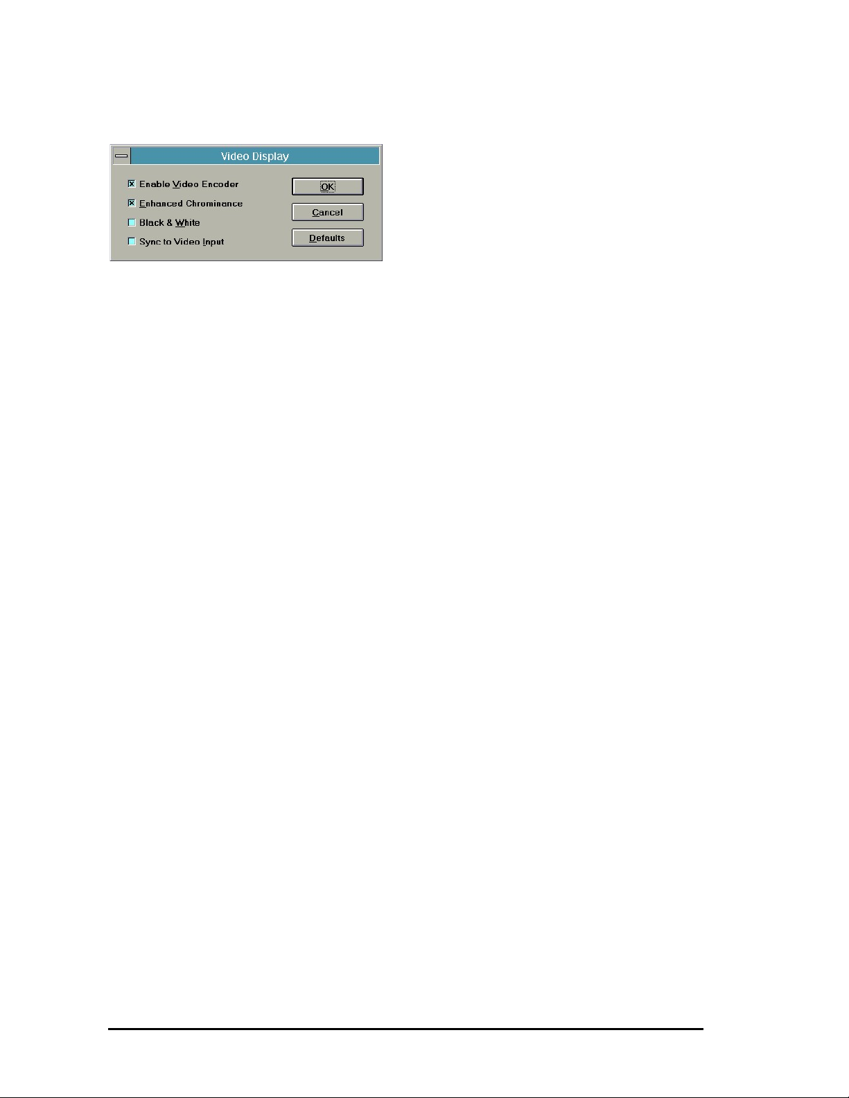
Video Display
This dialgoue sets the parameter required for
the video output (with Video Encoder).
- [X] Enable Video Encoder
If, in a video network, another video device
(than the video encoder) should produce a
video output on the video output of the SPEA
CRUNCH IT, deactivate this button [ ]. By
default, the video encoder should be enabled
[X] to generate video signals on the video
output.
- [X] Enhanced Chromincance
Generates the chrominance (color information)
with a higher range than the default range
before the color information will be modulated
onto the color carrier signal. For full resolution
you should set enhanced chrominance, for
smaller resolutions you should not use it.
- [ ] Black and White
If this option is activated [X], a black-and-white
shot will be generated, while [ ] generates a
coloured frame.
- [X] Sync to Video Input
With this setting, the video output can be run
parallel to the selected video input.
Thus you can mix the signal generated by the
SPEA CRUNCH IT afterwards with a video
mixer.This is only possible with a special video
equipment and therefore for a simple video
output with monitor or recorder this option
should be set to '[ ]'.
22
Page 23

Part 4
Part 5
Windows 95 Driver
Installation and
Configuration
The SPEA CRUNCH IT driver works with
Windows 95. As a final Windows 95 version is
not available yet, and additional changes and
adjustments will be necessary, we would like to
refer to the README file on the SPEA
installation disk #1 (or after the installation in to
the directory C:\SPEA\GDC) with all information about the current status concerning the
SPEA CRUNCH IT driver and Windows 95.
Video Maestro
VideoMaestro Programs
VideoMaestro is a collection of powerful tools
for capturing, creating and editing digitial video.
The following software is included in
VideoMaestro:
Video Capture
With the Video Capture program you can
capture and digitize video from a variety of
video sources, such as a video recorder, onto
your hard disk. All video capture boards which
are delivered with a Video for Windows capture
driver are supported.
The resulting AVI video file can then be played
back in any applications supporting the AVI
format (i.e. MediaMaestro) or edited using the
Video Editor software.
The software is extremely user-friendly and
intuitive. Setup options such as the video size,
color depth, compression rate, frames per
second etc. can be made in one dialog box.
Click on the Start button to start recording and
the file will be stored on your hard disk in the
AVI file format. A preview function is also
provided for playback of the recorded video.
Video Editor
With the Video Editor you can edit, splice, add
sound or titles to video files. New videos can
be created using existing video, animation,
image and sound files. Spectacular videos can
be created for desktop presentations (e.g.
MediaMaestro) and home video productions.
The easy-to-use 'drag and drop' interface lets
you put your video together in the Construction
Window in just minutes. On the File Selector
window you can preview all supported file types
on a thumbnail view before dragging and
dropping selected files onto the Construction
Window.
The files are then organized on a time line to
accurately define the sequence of events in the
resulting video. Existing video files (AVI,
FLI/FLC) can be edited to cut out unwanted
frames; sound (WAV) files can be edited to
adjust their duration and more than one sound
23
Page 24

file can be played at once during the video,
thus 'mixing' the audio track (i.e. useful for
playing music in the background with spoken
commentary overlayed).
Image files can be inserted inbetween video
sequences or two video sequences can be
'spliced' together to create a new video file.
Transition effects can be used between the two
video sequences to provide a smooth changeover from one video to the other.
An extensive Text function is provided for titling
video clips. The font, size and color of the text
can be selected and then the text block can be
placed anywhere on the screen. The ability to
create multiple text blocks allows for creative
titling.
Flexible options are provided for previewing the
newly created video sequence and for storing
the final version in AVI format. The size of the
video, color depth (256 or full color),
compression and number of frames per
second can be defined for the final AVI output
file.
Video Morph
With Video Morph you can create your own
morph videos as AVI files. Start with 2 image
files or capture frames from an existing AVI
video. Select the areas and contours to be
morphed with the easy-to-use grid.
Options are available to set the size, color
depth and the number of frames of the
resulting video. The video can be previewed
before writing it to the hard disk as an AVI file.
Videos created with Video Morph are great for
use in desktop presentations, screen savers
and home video productions.
Video Logo Generator
With the Video Logo Generator you can create
font logos which fly 3-dimensionally over the
computer screen. Save your creation to disk as
an AVI video file for use in desktop
presentations (i.e. in MediaMaestro), screen
savers or for inclusion in your own home video
productions.
The Video Logo Generator is easy to use. Text
can be added in the font, size and color of your
choice. Animate the text using transitions to
rotate it, zoom in or out or to move it in any
direction across the screen. A selected color or
an image file can be used as a background to
make the 'flying font' more effective.
Once the transitions have been defined, a
preview can be made. To create the final AVI
video file, settings for the size, color, number of
frames etc. can be made.
Video Screen Saver
The Video Screen Saver lets you display your
favorite videos from the hard disk or from a
CD-ROM drive when the computer is not in
use. A playlist of video files can be created by
'dragging and dropping' from the Windows File
Manager.
Flexible options for setting up the screen saver
such as display size, position, start and end
points as well as password protection are
provided. To play the screen saver, select the
display order, loop and sound on/off functions.
AVI, MOV, MPEG and the newest Video CD
titles can be included in the Video Screen
Saver!
Media File Finder
The fast and easy way to locate and display
any media files on your computer system,
network or CD collection. Enter the search
criteria - drive, path, media type and media files
in the File Finder window. All media files found
are displayed in thumbnail view where they can
be previewed or exported to associated
applications.
Flexible options are provided for configuration
of the file selector window. Image files can be
displayed as full image previews or as timesaving placeholder icons.
File formats supported include: AVI, MOV,
MPG, Video CD, FLI, FLC, MIDI, WAV, BMP,
EPS, GIF, JPG, PCD, PCX, RAW, RIF, TGA,
TIF and WPG.
Samples
Sample media in various formats is provided in
the Media subdirectory. Sample project files
(for the Video Morph and Video Logo
Generator programs) are provided in the
Samples subdirectory.
The sample project files for the Video Logo
Generator can be used as templates to create
your own video logos. Just open an existing
project file, replace the text and save the logo
as an AVI video file.
24
Page 25

MediaMaestro Demo Software
Also included on the VideoMaestro CD is a
demo version of Software Dynamic's popular
multimedia presentation software
MediaMaestro.
With MediaMaestro you can create full-featured
interactive multimedia presentations for
personal, business and home office use. Make
impressive presentations containing video,
animation, images, text, sound and music.
MediaMaestro is intuitive and easy to use. The
'drag and drop' interface lets you put stunning
presentations together in just minutes.
Interactive presentations can be created for
use in point of sale, training etc.
Standard business presentations can be made
more interesting by adding video sequences
and still images along with text, sounds and
music. Video formats supported include avi,
mpg* and dat (Video CD)* (*requires MPEG
decoder board). Image formats supported are
bmp, tif, pcx, gif, jpg and Photo CD. Sound and
music files in wav, midi and CD Audio format
can be added to presentations.
A flexible text function, screen underlays,
transition effects, pre-defined templates and
backgrounds, ready-made sample
presentations as well as a complete media clip
library are included in MediaMaestro.
A runtime version of MediaMaestro is provided
for distribution with presentations.
8. If "Build Program Group" was selected, the
MediaMaestro LE program group appears
on the screen. Click on the Readme icon to
read the latest release notes before starting
the software.
To install the MediaMaestro LE
demo software:
1. Insert the CD into the CD-ROM drive.
2. From the Windows Program Manager,
select Run from the File menu. In the Run
dialog box, type "(d):\mm_le\setup.exe".
Click on OK.
Note: (d) is the location of the CD-ROM
drive and may vary depending on your
system configuration.
3. The Setup program appears on the screen.
4. Select the destination path where you want
to install the software by typing in the text
box. Alternatively, use the default
destination path "c:\maestro.le".
5. Select the software modules you want to
install or use the default settings.
6. Select the language the software should be
installed in by making the appropriate
selection from the Language list box.
7. Click on the Install button to begin the
installation procedure.
25
Page 26

To view a sample presentation with
MediaMaestro LE:
1. From the MediaMaestro LE program group,
double-click the Runtime Player icon. The
Open dialog box will appear.
2. Select the desired demo from the
MM_LE>Demos subdirectory.
3. Double-click the desired filename to start.
To test the MediaMaestro LE
software:
1. From the MediaMaestro LE program group,
double-click the MediaMaestro icon. The
MediaMaestro LE program window will
appear on the screen.
2. To order your full version of MediaMaestro
software, please contact us at the address
given below.
26
Page 27

System Requirements
Hardware Requirements
IBM compatible PC/AT 80486
4 Mb RAM (minimum)
8-16 Mb RAM (recommended)
VGA or Super VGA video adapter
40-120 MB hard disk
Mouse
XA compatible CD-ROM drive
To take advantage of the functionality of the
software, the following optional hardware is
recommended:
Windows compatible sound card
SPEA Showtime board
SPEA CrunchIt board
Software Requirements
MICROSOFT-DOS 3.1 or higher
MICROSOFT-Windows 3.1 or higher
MCI (Media Control Interface)-Drivers for:
optional installed hardware
Video für Windows
Autodesk Animator
User Registration
To become a registered user, fill out the
registration form included on the VideoMaestro
disc.
Registered users are entitled to product
support and will be sent information about
software updates and new products when they
become available.
To fill out the Registration Form:
1. The Registration Form is located in the
subdirectory entitled:
Software\English\Readme.
2. Copy the file from the CD to your hard disk.
3. Open the file in Windows Write.
4. Fill in the requested information and print it
out.
5. Send it to us at the following address:
In Europe:
Software Dynamics GmbH
Am Fallturm 5
28359 Bremen
Germany
Fax: (49) (0)(421) 216718
In the United States:
Software Dynamics North America, Inc.
16135 New Ave., Suite 12
Lemont, IL 60439
U.S.A.
Fax: (708) 243-0622
Technical Support
Should you require technical support - for the
software only - we can be contacted from 10:00
- 15:00 on our support hotline at the following
telephone and fax numbers:
Telephone: 0421/219884
Fax: 0421/216718
User's Guide - Online Help
The User's Guide has been provided on CD for
your convenience in the form of an on-line Help
document which can be viewed by calling the
"Help" function from within each application.
Copyright Notice
VideoMaestro is a trademark of Software
Dynamics GmbH.
MediaMaestro is a trademark of Software
Dynamics GmbH.
© Software Dynamics GmbH, 1995
27
Page 28

VideoMaestro Getting Started
Video Editor
Playing Media Clips in the Video
Editor
Multimedia components such as video, sound,
music, images and text can be combined in the
Video Editor to create exciting video clips.
The Video Editor supports some multimedia
files through hardware, for example, a sound
card is needed to play sound and music files. A
software driver, which can be installed under
the Windows Desktop, must be installed in
order for the software to communicate with the
hardware.
Note:
Make sure that all hardware and associated
drivers are installed correctly before creating a
video project with the Video Editor.
Other media file types such as Autodesk
Animator and Video für Windows are
supported through a standard Windows MCI
driver. This MCI drivers must be installed
before a file of that media type can be played in
the Video Editor.
Note:
To find out which MCI drivers are installed on
your system, double-click the Drivers icon in
the Windows Control Panel. A list of all the
currently installed drivers will appear. To install
a new driver, follow the instructions outlined in
the Windows User's Guide.
Creating a Video with the Video
Editor
Basics of Video Editing
The first steps when planning a video (project)
with the Video Editor are:
Decide on an idea for your video.
Decide on the message you want to get
across with your video.
Locate the appropriate media in the form of
videos, animations, sounds and images that
will help you to get your message across
Use the many possibilites of overlay effects
for image and sound files·
Develop a text title or rolling credits for the
end of the video clip.
Creating a Simple Video Clip
The following steps describe how to create a
simple video clip in the Video Editor using
existing video files.
1. When you open the Video Editor program,
an empty Construction window will appear.
2. The filename (untitled) will appear in the title
bar of the Construction window.
3. Click on the Video icon on the Tool panel to
open a video file.
4. Select a video file (*AVI-file) from any
drive/directory and open it with a doubleclick.
5. The video preview window will open
automatically.
6. Click on the Play button to preview the video
files. This way you can be sure that you
have selected the correct file.
7. Click on the image in the Preview window
and drag the mouse over to Video Track 1
on the Construction window. Release the
mouse button. The file will be loaded into
the video track and the Preview window will
close.
8. Click on the video file with the mouse and
while holding the mouse button down, move
the video file to the desired location in the
Construction window.
9. Open a second video file, preview it and
then drag and drop it into Video Track 2 in
the Construction window.
10. Move the video file to the desired location
using the method described previously.
Note:
To move more than one video file, use the Ctrlkey to select multiple files. To select all files,
use the Select All command from the Edit
menu.
11. Edit the video file in Video Track 2.
12. Click on the right hand edge of the video
file. Holding the mouse button down, move
the double-headed arrow mouse cursor to
the left until the desired position is reached.
Release the mouse button. The video has
now been 'cut'.
13. Change the time scale to a low scale (for
example, to 1 frame for a short video file) to
see the effect of the 'cut' which was carried
out.
Note:
Double-click the edited file to re-open the
Preview window. The cut made to the video
can be seen on the gray bar underneath the
play buttons.
14. Only one track can be edited at a time. If a
video file contains a sound track, then the
28
Page 29

sound track must be edited separately.
Select the sound file in the Audio Track by
clicking in the blue area on the right hand
side of the file. Holding the mouse button
down, move the double-headed arrow
mouse cursor to the left until the desired
position is reached. Release the mouse
button. The sound track has now been 'cut'.
15. Should you click in the yellow area of the
sound track by mistake, a blue square will
appear on the middle line. The yellow area
of the sound track is for modifying the
transition and the volume of a sound track.
To move the blue square back to the neutral
position, click on the square and while
holding the mouse button down, drag it
back to the middle line and release.
16. Add a transition between the two videos in
Video Track 1 and Video Track 2.
17. Click on the Transitions button on the Tool
panel to open the Transitions window.
18. Select a transition effect and drag it to the
Transitions Track in the Construction
window. Close the Transitions window.
Note:
When a transition is dropped into the
Construction window, the duration of the
transition is always the same as the scale
which is set in the time scale list box. The
direction of the transition can be changed by
clicking on the gray area on the transition.
19. Make the transition the desired length
dragging the edge in the desired direction.
20. Save the video project file by clicking on the
Save button on the Tool panel.
21. To define the preview area for making a
preview of the video, move the gray bar at
the top of the Construction window in the
desired direction. Alternatively, click on the
red area at the end of the gray bar to make
the selection area larger or smaller.
22. Select Preview Options from the Options
menu. Set the size for the preview in the
Size list box to 160 x 120 and frames per
second to 5.
23. Click on the Video Preview button on the
Tool panel to start the video preview.
24. The preview window will appear and the
progress will be displayed on the status line.
Creating a Complex Video
The following steps describe how to create a
complex video containing video, sound,
images, spoken commentary and text titles.
1. Select New from the File menu or click on
the New icon on the Tool panel.
2. A new Construction window will appear on
the screen. The filename [Untitled] will
appear in the title bar.
3. Click on the File Selector button on the Tool
panel to open the File Selector window.
4. In the File Finder dialog, select the various
media types which you would like to include
in your video. (e.g. AVI videos, WAV files,
image files) by making the appropriate
selections in the file type, drive, directory
and file format list boxes.
Note:
Alternatively you can search for media files of
different types separately - for example, for
video files, for image files or for sound files
only.
5. An overview window will appear displaying
all the media files found matching the
search criteria. Media files can be displayed
as image previews or as placeholder icons.
6. All selected files appear highlighted to show
that they are selected.
Note:
When a file is selected on the File Selector
window, click on the Preview button. The
Preview window will appear. Click on the Play
button to preview the file before dragging and
dropping it into the Construction window. Using
this method, you can be sure that the correct
files have been selected before including them
in your video.
7. Select Tile Vertical or Tile Horizontal from
the Window menu.
8. Select the desired media files and drag and
drop them to the appropriate tracks on the
Construction window.
9. Made any edits to the media files.
10. Move all the media files to the desired
location in their respective tracks. Use
Select All from the Edit menu to select all
files and to move them all at the same time.
Note:
Make sure you save your video project to disk
at regular intervals!
11. Load a sound file and drag it to Audio Track
1. This sound track should fade out as soon
as the spoken commentary begins and then
fade in again once the commentary is
finished.
12. Load a sound file with spoken commentary
and drag it to Audio Track 2.
13. Select both sound files and move them to
the correct position.
14. Lower the volume of the sound on Audio
Track 1. To do this, click in the yellow area
and drag the blue square which appears
29
Page 30

downwards. Click several times on the
middle line to add more blue squares. Move
each blue square down to achieve the
desired fade out effect. At the end of the
spoken commentary file (Audio Track 2)
increase the volume by following the
procedure described previously.
Note:
Sound files can be loaded multiple times to
create interesting overlay effects or to repeat
the sound.
15. Add transition effects between the two video
tracks.
16. Click on the Transitions button on the Tool
panel to open the Transitions window.
17. Select the desired transition effects and
drop them onto the Transition track on the
Construction window. Close the Transitions
window.
Note:
When a transition is dropped into the
Construction window, the duration of the
transition is always the same as the scale
which is set in the time scale list box.
18. Lengthen or shorten the transition effect to
the desired length.
19. Create a first preview of the video.
20. To define the preview area, move the gray
bar at the top of the Construction window in
the desired direction. Alternatively, click on
the red area at the end of the gray bar to
make the selection area larger or smaller.
21. Select Preview Options from the Options
menu. Set the size for the preview in the
Size list box to 160 x 120 and frames per
second to 5.
22. Click on the Video Preview button on the
Tool panel to start the video preview.
23. The preview window will appear and the
progress will be displayed on the status line.
24. Choose Select All from the Edit menu to
select all files in the Construction window.
Move all the files together to the right.
25. Add a text title at the beginning of your
video project.
26. Click on the Text button on the Tool panel
and enter the desired text.
27. Select the size, font, foreground and
background color for the text. Click on OK.
28. The Text Preview window will open. If the
text display is correct, click inside the text
area and drag the text over to the beginning
of the Text Track on the Construction
window.
29. The text window will close automatically.
30. Adjust the gray preview bar at the top of the
window so that a preview of the text and the
first frames of the video can be made.
Note:
To delete files from the Construction window,
select each file using the Ctrl + mouse before
clicking on the Delete button on the Tool panel.
Tip:
A text title can be edited to change the text or
to include additional text blocks.
31. Click on the text in the Text Track.
32. The Text window will appear. Click on the
Add button to add another text block.
33. The new text will appear automatically in the
Construction window.
34. To add credits at the end of a video, click
again on the Text button on the Tool panel.
Enter the desired text and drag the text
block to the appropriate location on the Text
Track at the end of the video.
35. Adjust the gray preview bar at the top of the
window to include the complete length of
the video so that a preview can be made.
Note:
Alternatively, select the option Whole Project
from the Preview Options dialog box.
36. Open the Preview Options dialog box from
the Options menu to adjust any settings for
the video preview.
37. Click on the Video Preview button on the
Tool panel to view the complete preview of
your video.
38. After making sure that the video is the way
you want it with the video preview, it can be
written to the hard disk as an AVI (Video for
Windows) file.
39. Select Output Options from the Options
menu. Make any necessary setting for
generating the final video file.
40. Click on the Save Video button on the Tool
panel. Your video will now be saved to disk
in the AVI file format.
30
Page 31

Video Morph
Creating a Morph Video
With Video Morph you can create a video file
from two images or captured frames from an
existing AVI file. A special transition - the
morph transition - is used to create interesting
video clips.
The first step when creating a morph video is
to load the source file and the destination file.
The source file is the starting point of the
morph; the destination image is the end point
of the morph.
Note:
To achive the best results, the source file and
the destination file should be approximately the
same size and of the same proportion. Ideally,
both images should have the proportion 4:3 or
3:4.
1. When the Video Morph program is first
opened, an empty window will appear.
2. The filename [Untitled] will appear in the title
bar.
3. Click on the Load Source Image button to
load a source file.
4. Select the desired file format.
5. Change the drive and directory if necessary
to locate the desired file.
6. Double-click the filename to open it. If a
video file was selected, a preview dialog
box will appear where a single frame from
the video can be selected.
7. The selected image will appear in the
window.
8. Click on the Load Destination Image button
to load the destination file. Proceed as
described previously.
9. The selected image will appear in the
window.
10. Set the horizontal and vertical grid lines to
define the areas which are to be
transformed, i.e. morphed.
Note:
The number of grid lines required depends on
the images chosen. As a general rule, the
more detailed the image, the more lines
required. A higher number of lines also
generates a smoother morph effect.
11. Click on the Vertical Line button and move
the mouse over the source image. The
mouse cursor will turn into a cross.
12. Move the cross to the desired position and
click on the mouse to draw the line. A line
will appear in the same position on the
destination image.
13. Click on the Horizontal Line button on the
Control panel.
14. Move the cross to the desired position and
click on the mouse to draw the line. A line
will appear in the same position on the
destination image.
Note:
Once positioned, lines cannot be moved. To
move a line, it must be deleted and a new line
placed at the desired location.
15. The first grid lines should be set to trace the
contour or outline of an object. More lines
can then be added within the object to refine
the grid and to define focal points.
16. Move the resulting intersection points to
achieve a smoother morph effect.
Note:
Intersection points can be divided into two
types: Contour Points and Focal Points.
Contour Points are used to define the contour
or outline of an object. Typical Contour Points
are placed at the edges of an object, thus
tracing the shape of the desired area.
Focal Points are used to define the central or
prominent features of an object. Typical Focal
Points are, e.g., the eyes, nose and mouth of a
face.
17. Click on the Move Points icon on the
Control panel.
18. Click on the intersection point that you want
to move by holding the mouse down and
moving the point to the new position.
Note:
The intersection point can only be moved within
the square image display area.
19. When a point is selected on one image, the
corresponding point on the other image will
be highlighted in red.
20. If necessary, lines can be deleted.
21. Click on the Delete button on the Control
panel.
22. Move the cross icon to the line that you
want to delete. Click on the mouse to delete
the line. The corresponding line in the other
image will also be deleted.
23. Save the Morph project file by selecting
Save from the File menu. The project will be
saved to the hard disk with the file
extension *.mph.
Note:
If necessary, the complete grid can be deleted
so that a new grid with new intersection points
can be created.
31
Page 32

24. Click on the Delete Mesh button on the
Control panel.
25. All grid lines will be deleted.
26. Click on the Options button to set the
number of frames for the preview to a low
number.
27. Click on the Preview button on the Control
panel.
28. The Preview window will appear where
various views of the morph video can be
seen, for example, only the image, only the
mesh or both.
29. The video can be previewed frame by frame
with the Frames scroll bar. Each frame will
be displayed in the window along with its
corresponding frame number.
30. After the mesh has been edited and a
preview made, the final video file can be
written to disk.
31. Click on the Options button to select the
settings for the final video file.
Note:
To create a smoother morph effect a higher
number of frames should be selected.
32. Click on the Start button in the Control
panel.
Note:
The project must be saved before the video
can be saved to disk. If this has not been done,
a warning message will appear.
33. The progress dialog will appear while the
video is being written to the hard disk.
Note:
The generation of the morph video can be time
consuming depending on the options set and
on the system configuration being used.
34. The video will be written to the hard disk
and an AVI file.
35. Click on the Play button on the Control
panel to view the morph video.
36. The Preview window will appear and the
video will start to play automatically.
Use the many possibilites available for three
dimensionally rotating and moving a logo on
the screen.
Decide on the number of transitions
required to achieve the desired result.
Video Logo Generator
Creating a Video Logo
The first steps when planning a video logo with
the Video Logo Generator are:
Decide on an idea for your logo.
Decide on the effect you want to create with
your video logo.
32
Page 33

Creating a Rotating Logo
The Video Logo Generator requires at least
two transitions to be able to generate a video
file. To create a more complex logo, a higher
the number of transitions must be created to
achieve the desired effect (see Example 2).
The following steps describe a rotating video
logo with two transitions. The logo will rotate on
one axis from top left to bottom right and will
change in size at the same time.
1. Open the Video Logo Generator. An empty
window will appear.
2. The filename [Untitled] will appear in the title
bar.
3. Click on the Add button.
4. The transition entitled Transition 1 will be
added to the play list.
5. Click on the Edit button.
6. The window entitled Edit - Transition 1 will
open.
7. You can now enter your logo text.
8. Click on the button entitled ABC. The Text
and Style window will appear.
9. Enter the desired text in the text field and
set the font and size.
10. Set the color of the text in the area under
Face Color and the shadow color for the
text under Side Color. Click on OK.
Note:
The logo text entered always applies to the
whole project. Any changes made to the text,
such as the text itself, font or style, are global
changes which will then take effect in all
transitions in the project. In each transition,
only the position of the text is changed.
11. Edit the position of the text in Transition 1:
Move the scroll bar of the z-axis all the way
to the right. The text will be displayed far in
the background in the preview window
12. While the logo moves forward into the
foreground, it should rotate around the xaxis. Enter the value 2 in the text box beside
the "x".
13. Confirm these steps by clicking on OK.
14. Click on the Add button once again.
Transition 2 will appear in the play list.
15. Click on the Edit button.
16. The Edit - Transition 2 window will appear.
17. Edit the position of the text in Transition 2:
Move the scroll bar of the z-axis back to
position 0. Change the value on the x-axis
to 200 and on the y-axis to -100. The text
will be displayed in the foreground in the
preview window.
18. Save the project to disk by clicking on the
Save button.
19. You can now use the preview function to
make a preview of the logo. To generate a
faster preview, it will be displayed in wire
mesh mode.
Note:
In the Settings dialog box the contour of the
text can be modified. The Points per Curve
option defines the form of the text. For
example, the higher the number, the better the
letter will appear. This is especially noticeable
for letters such as C, O or G. When the highest
numbewr (9) is set, the generation of each
letter is time intensive. Therefore it is
recommended that while editing the logo and
when generating the first preview video, the
value should be set to a low number betwen 1
and 3. The number should then be changed to
the highest value (9) just before the final video
is written to disk.
20. Select Transition 1 in the play list and then
click on the Preview Play button. All
transitions in the play list from the selected
position will be displayed in the preview.
Note:
It is recommended to check your logo with the
preview function before writing the final video
file to disk. Writing the final video file can be
very time consuming (depending on the options
used) and any change made to a transition,
either in the text, position etc., means that the
output video file must be regenerated.
21. Further edits to the video logo can be made.
Select Transition 1, for example, and click
on the Edit button.
22. Click on the Horizon button to turn the
horizon of the logo on.
23. To change the position of the horizon, click
on the grid and while holding the mouse
button down, move the grid in the desired
direction.
24. Confirm the settings by clicking on the OK
button.
25. Click on the Model button to view the logo in
solid mode. In this view you can see the 3D
effect and the effect of the text colors
selected.
26. You can now change the light direction. It
might be necessary to change the
background color to a darker color to see
the position of the light direction.
27. Click on the Light Direction button. The light
bulb will appear as if it is switched on. Enter
a value in the x, y and z axes to change the
position of the light direction.
28. Click on the Settings button and change the
Space depth, for example, to a value of
750. Click on OK.
33
Page 34

29. Click again on the Light Direction button.
The solid model of the logo will be
displayed. Set the desired space depth in
the Options dialog box.
30. The last step when creating a video logo is
to generate the final output video and save
it to disk.
Note:
The filename and the directory where the
output file will be written is the same as for the
project file. The project must therefore be
saved to the hard disk before the video file can
be generated. If this has not been done, a
warning message will appear requesting you to
save the project file to disk before attempting to
generate the video file.
31. Depending on the options chosen for the
output video, the amount of time required to
generate the output video file can be very
long and the amount of disk space required
high. Click on the Options button and select
Full Color, the smallest size and for
example, with 2 transitions, the value 10
frames.
32. Click on the Start button to start the
generation of the video file.
33. Your video logo is now saved to the hard
disk in the AVI file format.
34. The final video can be viewed by clicking on
the Play button. The preview window will
appear.
Note:
Changes the settings for the final video (e.g.
frames per second, points per curve) only after
all editing has been completed.
A Multiple Rotating Logo with a
Background Image
A number of transitions and steps are required
to generate movement of the text logo to
create the desired effect. For example, your
logo could consist of ten transitions, rotating on
all 3 axes while moving through the space
depth into the foreground.
1. Click on the New button to create a new
project.
2. Click on the Image button to load the
desired background image.
Note:
The Video Logo Generator supports the BMP
graphic file format. All color depths are
supported but it is advisable to use the same
color depth for the image as the output video to
avoid generating huge amounts of data. For
example, if the output video is to be written in
256 colors, then the image file loaded should
also be in 256 colors.
3. All files in the *BMP file format in the current
directory will be displayed.
4. If necessary, change the drive and directory
to find the desired image file.
5. Double-click the file to open.
34
Page 35

6. The background image will be displayed in
the preview window.
35
Page 36

Note:
When the image has been loaded into the
preview window, the horizon should be
adjusted to the image. The Horizon button in
the Edit window is used to turn the horizon
display on or off. The horizon can be changed
by clicking on the mesh with the mouse and
while holding the mouse button down, moving
in the desired location.
7. Click on the Add button.
8. A new transition entitled Transition 1 will
appear in the play list.
9. Click on the Edit button.
10. The Edit - Transition 1 window will appear.
11. Enter your logo text.
12. Click on the ABC button. The Text and Style
dialog box will appear.
13. Enter the text and set the style and size.
Note:
In the Settings dialog box the contour of the
text can be modified. The Points per Curve
option defines the form of the text. For
example, the higher the number, the better the
letter will appear. This is especially noticeable
for letters such as C, O or G. When the highest
numbewr (9) is set, the generation of each
letter is time intensive. Therefore it is
recommended that while editing the logo and
when generating the first preview video, the
value should be set to a low number betwen 1
and 3. The number should then be changed to
the highest value (9) just before the final video
is written to disk.
14. The face color of the text can be selected in
the Face Color area of the text dialog box.
The shadow color of the text can be set in
the Side Color area. Once these colors
have been selected, click on OK.
15. Enter the position on each axes in
Transition 1. The position of the text will be
displayed in the Preview window.
16. Click on OK.
17. Add more transitions into the playlist with
the Add button and edit them as desired.
Note:
To have a better overview of all the transitions
in the play list, each transition can be renamed
with the Rename button. The transitions can
also be moved within the playlist by using the
Up and Down buttons.
18. With the Model button, the text can either
be displayed as a wire frame model or as a
solid model. For faster text display, the wire
frame model should be used.
Note:
For faster display, set the points per curve to 1
in the Points per Curve list box in the Options
dialog.
19. The Image button in the Edit window can be
used to turn the image display on or off.
20. The logo will be displayed in the Preview
window as a wire frame model so that the
transition effects can be previewed.
21. To start the preview, click on the Play
button. All transitions from the currently
selected transition will be displayed. Click
on the Stop button to stop the preview.
22. The last step when creating a video logo is
to generate the video logo save the video
clip to the hard disk.
Note:
The project file must be saved to disk before
the video clip can be written. If the project has
not been saved, a warning message will
appear reminding you to do so.
23. Depending on the options chosen for the
output video, the amount of time required to
generate the output video file can be very
long and the amount of disk space required
high. Click on the Options button and select
Full Color, the smallest size and for
example, with 2 transitions, the value 10
frames.
24. Click on the Start button to start the
generation of the video file.
25. The final video can be viewed by clicking on
the Play button. The preview window will
appear.
26. Your video logo is now saved to the hard
disk in the AVI file format.
Note:
Changes the settings for the final video (e.g.
frames per second, points per curve) only after
all editing has been completed.
36
Page 37

Appendix A
Utilities
The SPEA Utilities help you to configure or
optimize your system environment to get the
full use of all the features supported by SPEA.
CRUNCH IT INIT - Protecting the
Video Monitor and TV from
damaging Signals
After you switch on or reset your PC, the video
output of the SPEA CRUNCH IT finds itself in
an undefined state. If this signal is sent to a TV
or video monitor for a longer period, the device
can be damaged.
To avoid this, the SPEA CRUNCH IT is
initialized with the program CRITINIT.EXE.
The syntax for this program is as follows:
<Path>CRITINIT $<Address> <Norm>
<Path> drive and directory you have copied
the file to (C:\SPEA\CRUNCHIT).
<Address> base address, for which you have
configured your SPEA CRUNCH IT
under Windows
<Norm> video format for which the video
output of the SPEA CRUNCH IT
should be initialized. Possible video
formats are PAL and NTSC.
Example:
C:\SPEA\CRUNCHIT\CRITINIT $280 PAL
C:\SPEA\CRUNCHIT\CRITITIT $300 NTSC
Test- / Diagnostics program
This progam will be available with the next
software release.
37
Page 38
Appendix B
Technical Details
Technical Data
ZORAN ZR 360/055 Motion JPEG
Controller
Video Decoder: Philips SAA7110
Video Encoder: Philips SAA7199B
Video Standards: PAL, NTSC, SECAM
Video Inputs: 2 x FBAS, 1 x Y/C
Video Outputs: 1 x FBAS, 1 x Y/C
Audio Input and Output: No
Digitizing: YUV 4:2:2
Frames per second: 25 (PAL), 30 (NTSC)
Sampling Rate: 14,75 Mhz (PAL), 12,27
MHz (NTSC)
max. display resolution (pixels): 768 x 576
(PAL), 640 x 480 (NTSC)
max. compression resolution (pixels): 768 x
576 (PAL), 640 x 480 (NTSC)
Compression,
dynamic: 1:5 (8) - 1:100 (full resolution),
static: Data rate per frame free adjustable
Overlay: No (optional via SPEA SHOW-
TIME PLUS or SPEA PLAY IT)
TV Tuner: No
SPEA Movie Bus (see next section in this
manual)
Pinout of the SPEA Movie Bus
The SPEA CRUNCH IT is equipped with a
digital video bus connector. This is not a
Feature Connector, but the 'SPEA Movie
Bus'.
This connector can be connected with the
multimedia board SPEA SHOWTIME PLUS or
with the SPEA PLAY IT.
The default pinout of this connector is:
Pin Function Pin Function
1 SCL (bi) 2 GND
3 SDA (bi) 4 ODD (bi)
5 FEIN (in) 6 FEOUT
7 HREF (bi) 8 GND
9 HS (bi) 10 VS (bi)
11 LLC2 (bi) 12 GND
13 CREF (bi) 14 GND
15 LLC (bi) 16 GND
17 UV0 (bi) 18 UV1 (bi)
19 GND 20 UV2 (bi)
21 UV3 (bi) 22 GND
23 UV4 (bi) 24 UV5
25 GND 26 UV6 (bi)
27 UV7 (bi) 28 GND
29 Y0 (bi) 30 Y1 (bi)
31 GND 32 Y2 (bi)
33 Y3 (bi) 34 GND
35 Y4 (bi) 36 Y5 (bi)
37 GND 38 Y6 (bi)
39 Y7 (bi) 40 GND
The connector pin numbers are marked on the
circuit board itself.
Three operation modes are possible with the
SPEA CRUNCH IT:
1. video in (e.g. video cassette recorder, TV
Tuner etc.) is active
2. video decoder is active
3. an external board is active
The function of the pinout of the SPEA Movie
Bus changes for each mode.
If you need more detailed information about the
pinout (and its changes) of the SPEA Movie
bus, you can request a technical specification
from SPEA Software AG (address to
'Customer Support').
38
Page 39
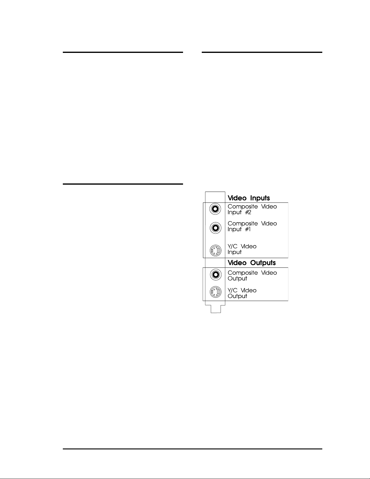
I/O Addresses of the SPEA
CRUNCH IT
The Connections of the SPEA
CRUNCH IT
In order for your system to function properly it
is necessary to make sure that all the I/O
addresses reserved for the SPEA CRUNCH IT
are not used by other hardware devices.
Normally the board should be configured
automatically, the default is:
280 - 28F (hex)
However, the board can be reconfigured in
freely selectable steps (+10 (hex)):
200 (hex) - 20F (hex)
: :
3F0 (hex) - 3FF (hex)
IRQ setting of the SPEA
CRUNCH IT
A free IRQ has to be assigned to the SPEA
CRUNCH IT.
Default for the SPEA CRUNCH IT is IRQ 15.
You can also use IRQ 10, 11 or 12 instead.
The board has 3 inputs and 2 outputs as seen
from the side of the board.
Video Inputs
Composite Video In #1 and #2:
These inputs are connected with a Video
recorder or Camcorder output. Please
note, that the antenna signal from the
wall socket is not suitable!
Y/C Video In for e.g. S-VHS or Hi-8:
See description 'Composite Video In' above.
Video Outputs
Composite Video output: for connecting a
video monitor or a video recorder
Y/C (S-VHS, Hi-8) Video output:
For connecting a S-VHS or Hi-8 video
recorder.
Video inputs and outputs of the SPEA
CRUNCH IT
39
Page 40

Appendix C
Troubleshooting
General Considerations
Make sure the SPEA board is firmly seated in
its 16 bit ISA expansion slot, and that it is not
touching other boards in your system.
Be sure your monitor cable is properly
connected to the SPEA board and that your
monitor power switch is on. You may also need
to verify your cable pinout, since some
monitors use a non-standard configuration.
Make sure other peripherals such as EMS
cards, disk controllers or LAN cards are not
using the same memory address as the SPEA
board. Check with the manufacturer or your
user's manual for information about
designating exclusions for memory locations
when invoking your device driver.
Some other things to think about
Your AUTOEXEC.BAT or CONFIG.SYS file
may contain commands that are interfering
with the operation of the SPEA board (e.g. if an
elder graphics board or an MPEG Deocoder
was installed before). Try booting your system
without these files. If the SPEA board works
properly, identify and remove the conflicting
command(s).
Hardware settings
When installing the SPEA CRUNCH IT, you
should beware of possible hardware conflicts
with other adapter cards in the computer. It is
possible that two or more cards in the
computer are contending for the same
resources. These conflicts can involve:
IRQ line (Interrupt Request)
I/O port address (Input / Output)
Devices to be wary of:
When setting up IRQ and I/O ports, be
especially aware of the following hardware:
scanner card, SCSI drive, tape streamer,
additional sound card, hard/floppy disk drives,
modems, serial ports, mice, networks and
others.
IRQ settings
The computer is likely to be using various IRQ
lines already, through hardware handlers for
disk drives, printer ports, keyboard, coprocessor, and others. MS-DOS 6 ships with
the utility MSD, which shows you what IRQs
are/aren't being used. Once you know this
information, you can set the IRQs of the SPEA
CRUNCH IT correctly.
Here is an example for likely IRQ usage:
IRQ 4 active serial port
IRQ 3+4 two active serial ports
IRQ 7 print spooler or SoundBlaster
IRQ 2, 3 or 12 mouse
IRQ 15 E-IDE interface 2
I/O port address
This is the address via which a particular driver
or device can be communicated with.
Reserved I/O addresses for example are :
3F8 - 3FF COM 1
2F8 - 2FF COM 2
3E8 - 3EF COM 3
2E8 - 2EF COM 4
378 - 3FF LPT1:
300 - 31F various network cards
Input Video Signal
During the driver configuration or when you
start the video editting software system
software crashes may occur if there is no video
signal present at the video input of the SPEA
CRUNCH IT.
In this case terminate Windows, activate a
video signal and then restart Windows.
System Performance
The quality of your edited video depends on the
single components of your system
environment. Besides a quick processor, the
type of hard disk used is very important (see
also 'Part 2, Tips and Tricks for installing the
SPEA CRUNCH IT).
No general rule can be given for setting a
compression rate . To find out the optimal
setting for your sytem simply try various
alternatives.
Configuration Problems with
PCI Motherboards
40
On PCI boards problems may occur while
configuring the interrupts in the event that the
PC's BIOS assigns each interrupt for PCI
boards automatically. In this case, find out
(before you configure the SPEA CRUNCH IT)
which interrupts will be reserved by the PCI bus
or in the system setup definition, which
interrupts should be available for the ISA bus
Page 41

Frequently Asked Questions
General problems
Q: The system does not work properly, some
problems occurred while the graphics board
has been installed.
The system beeps when booting.
The graphics board cannot be initialized.
Problems with the network occur.
A: Check again, if all connections are correct
and if the graphics board is placed secure in
the expansion slot.
Be sure that you have installed the most up
to date software driver. (You can find them
in the SPEA mailbox. If you don't have a
modem, please contact your local dealer).
Remove all other hardware (e.g. soundboard, networking card) from your system in
order to find out possible hardware conflicts.
Install the SPEA CRUNCH IT in another slot
(more outwards) or - if available- in another
system.
Minimize the clock rate of your system.
Q: DOS 6.0 (5.0): General Problems with
Windows
A: Check the following entries in the
CONFIG.SYS file:
HIMEM.SYS, QEMM386.SYS or
386MAX.SYS must stand at the first
position.
Q: The installation program of the SPEA
CRUNCH IT does not work correct.
A: Add the following entry to the
AUTOEXEC.BAT file and restart your
system:
SET COMSPEC=C:\DOS\COMMAND.COM
Problems with Windows
Q: The Windows startup lasts very long.
A: Create a permanent swap file.
Defragment your hard disk regularly (e.g.
with Norton SpeedDisk).
Remove unnecessary entries from your
WIN.INI file (e.g. fonts, programs).
Q: Windows or applications unter Windows
crash.
Mouse functions or icons are not correct.
Wrong colors are displayed.
A: Set - depending on the SETUP of your
system - DEQUOPLE REFRESH,
REFRESH=HIDDEN, REFRESH=ATSTYLE or REFRESH to 'disabled'.
Use COM port #2 for your mouse.
Problems with the Playback and
Editing of Video Sequences
Q: When recording a video sequence, the
capture software always reports, that xx
frames have been dropped during the
recording.
A: Settings in the Video Software:
You have chosen the settings for the video
data stream (video format, compression,
frames per second and sound quality) in a
way, that the system was unable to follow it.
Reduce the data quantity, so that the
system can handle it.
A / V hard disks:
Hard disks with a special Audio / Video
Firmware provide a constant data flow and
avoid this problem.
Zone Bit Recording:
Modern hard disks record less sectors on
the inner tracks (=Zone Bit Recording) than
on the outside tracks. Because it is filled
from the outside to the inside, it will get
slower the more it is filled.
Defragment your hard disk:
Defragment the hard disk you save the
video data on. MS-DOS provides the utility
DEFRAG for this purpose.
Deactivate the Cache function:
Switch off the option 'write caching' for the
drive where you are storing the video data.
Install 32 bit driver:
Install a 32 bit driver for the hard disk under
Windows, if not already installed. You can
find additional information about this in your
Windows manual or in the operating
instructions of your hard disk (IDE) of of
your hard disk controller (SCSI, ESDI).
41
Page 42

Q: It seems that the video playback is not
smooth.
A: Please consider all notes for the question
before. Besides that:
Changing the settings:
If the video data stream contains dropped
frames, the video is not played back
smoothly. Please take note of the steps
described above. If the data flow defined is
very close to the maximum data rate, it may
occur that Video for Windows doesn't
receive the necessary data in time.
Reduce the data flow as far as possible until
the effect disappears.
Read Cache:
It can also help to add a read cache for the
drive with the video sequences.
Swap file:
Set up a permanent swap file with double
the size of the available RAM of your PC,
the minimum should be 20 MB!
42
Page 43

Appendix D
Glossary
Analog Display
A monitor that uses variable color control
voltages to display a very large number of
colors but requires very few inputs.
ANSI
American National Standards Institute.
ASCII
American Standards Committee on Information
Interchange. A standard used by IBM and
compatible computers to represent numbers
and characters in binary form.
Authoring Systems
Authoring systems are used to create
multimedia applications. They combine existing
presentation information (texts, images and
sound) and control the flow of these during the
multimedia show. The dialogue with the user is
controlled with this software. The individual
information must have already been created
and saved with special programs.
AUTOEXEC.BAT
A batch file that directs the activities performed
by the computer during system startup.
AV Hard disks
Hard disks with a special audio / video
firmware which ensures a constant data flow.
Recalibrations that could interrupt the data flow
are suppressed and an internal recording
format is used on the hard disk.
AVI
Audio Video Interleaved. AVI files are the
standard format for digital video films on PCs.
Bandwidth
The required capacity for the data volume and
transmission rate.
BIOS
Stands for Basic Input-Output System. Code in
your computer's ROM (Read Only Memory)
that provides the power-on self test and other
operating functions.
BitBlt
Bit Block Transfer refers to the ability of a
system to move pixel blocks (in a rectangular
area, e.g. in a window) very quickly. The
contents of the rectangular area are rapidly
refilled with the orginal contents.
BMP (Windows Bitmap)
This format enables Microsoft Windows to
display images on devices with similar
capabilities in a consistent way. Save pictures
in this format if you wish to continue to process
them later under Windows.
Booting/Booting Up
Starting the computer. There are two types.
Warm booting is accomplished by
simultaneously pressing the CTRL/ALT/DEL
keys and can occur only when the computer is
running. A cold boot requires activation of the
ON/OFF switch.
Brightness
The brightness of an image is determined by
the amount of light emitted by it. No light
(black) therefore means 'no brightness',
whereas pure white light menas 'maximum
brightness'.
CD-I
Compact Disc Interactive. A technique
developed by Philips in order to playback
games, films and music videos on a CDI
player.
CD-ROM
High-density medium to store digital data. CDROMs have read-only status. There are
different CD-ROM formats:
YellowBook: conventional CD-ROM format
GreenBook: used for linear video, this is typical
for CD-I's (see below)
WhiteBook: used for Digital Video VideoCDs.
CGA
The IBM Color Graphics Adapter.
Channel Number
A MIDI device can have three connections MIDI-In, MIDI-Out and MIDI-Through. The last
is used to pass on data group information
without changing it. This enables the user to
cascade several devices. To select a particular
device, the MIDI information is passed on to an
identifying channel number from 1 to 16.
Cinepak
Software-Codec. Makes fast decoding
possible. Good image quality possible as long
as the image dimensions are not increased.
The video encoding process is timeconsuming.
43
Page 44

CODEC
Compressor / Decompressor, responsible for
the compression and decompression of image
data.
44
Page 45

Color Display
A type of monitor capable of displaying
information in color. It is often called an RGB
(red, green, blue) monitor, referring to the
signals needed to drive it.
Color Palette Conversion
Conversion of video data from the YUV color
model into the RGB color model, or v.v.
CONFIG.SYS
An ASCII file that is created to provide the
computer with special information about
applications and hardware.
Contrast
The contrast of an image is the difference
between light and dark. A contrast-intensive
image is one in which contains strong
transitions from light to dark. A contrast-weak
image contains transitions that are hardly
noticeable.
Data Transfer Rate
The data transfer rate describes the amount of
data transferred to or from the storage medium
(e.g. hard disk) per second. Each data storage
medium has a specific data transfer rate which
it can handle. Typical values are:
- old hard disks 300 KB/s
- new hard disks 600 KB/s
- standard CD-ROM drives 150 KB/s
- DoubleSpeed CD-ROM drives 300 KB/s
DCI
Display Control Interface. An interface defined
by the Intel and Microsoft corporations, which
enables enhanced graphics performance due
to direct access to the video memory.
Default Mode
The capabilities, resolutions and display mode
the system operates with when you start your
computer.
Digital Display
Also called TTL. A type of monitor that
switches signals ON or OFF to determine
display color. Types of digital displays include
the IBM Enhanced Color Display or
Monochrome Display.
Digital Video
Digital videos contain optical information
bitwise in a file.
DIP Switch
Dual Inline Package switch; a series of tiny, two
position switches which allow users to select
and change options on computer boards,
printers, and other peripherals.
45
Page 46

Driver
Part of a software program that interacts with a
particular piece of equipment in your computer
system (i.e. video boards, printers, and
keyboards). Drivers are often loaded by your
config.sys at system boot.
Dropped Frames
The images of a video which are not displayed
or recorded when replaying (resp. recording).
EEPROM
Electrically eraseable programmable read only
memory; used to replace DIP switches and
jumpers on new graphics boards like yours.
EGA
The IBM Enhanced Graphics Adapter.
EMS
Enhanced Memory Specification. Originally
developed to break the DOS 640K limit, it is
now used as a general term for types of add-in
memory.
Enhanced Color Display (ECD)
The IBM Enhanced Color Display capable of
640 x 350 resolution.
EPS (Encapsulated PostScript)
EPS is a device-independant file format, which
contains all the information required to
reproduce an image directly on a PostScript
printer or to use it in suitable applications. A
small header section contains the data of the
image als a TIFF-format file so that
applications that can not display PostScript
data directly can still obtain an impression of
the file contents.
Expansion Board
A device used to expand a computer's
capability.
Expansion Slot
An electrical connection within the computer
used for the addition of Expansion Boards.
Fill-in Images
When video data is being saved onto a CDROM (during manfacturing) the images are
normally 'polstered' with fill-in images so that
each video file completely uses the assigned
2KB area. This ensures a constant data rate
and a smoother playback appearance. The file
size is not changed by doing this.
Fixed Frequency Monitor
An analog monitor which can only sync to a
very narrow range of scan frequencies.
fps
frames per second. Measurement unit for the
frame rate.
Frame
Single video image.
Frame Rate
Number of images shown per time unit.
Software videos have a fixed frame rate. When
playing back the actual frame rate achieved
can differ to the rate defined in the video
considerably.
Framegrabber
If an overlay board (see below) also contains a
realtime video digitizer (= frame grabber), then
the user can capture a random frame from the
video sequence being replayed and can save
this onto his hard disk.
General MIDI
The MIDI Association's MIDI Song File
standard has established itself as the General
MIDI standard for the exchange of MIDI music
data between different PC systems.
GIF (Graphics Interchange Format)
A graphics file format developed by
CompuServe to enable the device-independant
exchange of images between systems. GIFformat files can be up to 64MB in size with
color information up to 256 colors (8 bits). GIF
files do not contain information about the
image resolution.
Greyscales
A greyscale image consists of different shades
of grey (like a black-and-white photograph).
This normally menas that 254 different
greyscales plus black and white (= 256) are
used.
Hardware Cursor
The cursor's movements and display are
controlled by the accelerator chip. This means
that the CPU only has to pass the mouse coordinates to the graphics board, reducing the
CPU's workload.
Hercules Graphics Card (HGC)
A video adapter that provides bit mapped
single color graphics.
46
Page 47

Hexadecimal Notation
A base-16 numbering system that uses
numbers and letters. The hexadecimal
sequence begins: 1 2 3 4 5 6 7 8 9 A B C D E
F, then 10, 11 etc.
Horizontal Frequency
The rate at which a monitor displays each scan
line. Usually measured in kilohertz (kHz).
I/O Port
Input/Output port. An address used to access a
hardware device.
Image Compression
Technique used to reduce the volume of data
in digital image and video files.
INDEO
Intel Video. Compression technique developed
by Intel. Gives good quality but requires a high
level of processing work to decompress.
Indexed 16 and 256 Color Images
Indexed color images contain a color table in
the file. This table lists all the colors that could
be used in the file. An indexed 16-colour image
contains a table with 16 colour entries (4 bits)
whereas an indexed 256 colour image 256
colours are listed (8 bits).
Other colors can be simulated in a way similar
to using greyscales in a black-and-white image,
by simply positioning the pixels in varying
densities. The eye then sees color mixtures
that are not actually in the color table.
You can transform images into indexed color
images in order to load them into programs
such as Windows Paintbrush, or just to see
them on monitors that can only display 256 or
16 colors.
Interlaced Display
A monitor that refreshes every other scan line
every other pass of the screen. A noninterlaced monitor refreshes the entire screen
(every scan line) every pass of the screen.
Interleave
A technique used to organize audio and video
data so that every audio data segment is
followed by video data, e.g. AVAVAV.....
Interrupt Request (IRQ)
Signal used by a device, such as a mouse, to
inform the CPU that it is present and
functioning.
JPEG
A new compressed file format industry
standard developed by the Joint Photographic
Experts Group. It enables compression ratios
up to 100:1 (original file size to compressed file
size). A new feature of this standard is that it is
device-independant. These files can be
replayed using any application that supports
this format. JPEG differs from the LZW
47
Page 48

compression method in that it works with
quality loss. This means that some of the
original data is lost during the compression
phase. In order to surpass this visual effect
JPEG compression attempts to 'lose'
information which is less important to the
human eye. Use this format if you don't have
much memory space available or if you are
processing very large image files.
Jumper
A small plastic plug that fits over a pair of pins.
When the plug straddles two pins it makes an
electrical connection. The computer makes
decisions based on whether the connection is
made or not. A group of jumper pins is called a
jumper block.
Keyframe
Technique used to compress video data
whereby certain frames are defined as
'keyframes' and are fully saved during
compression. The video data of the frames
between two keyframes are only partially
stored. During decompression the 'partial
frames' use the information stored in the
keyframes.
Line Drawing
This is a hardware function of the graphics
processor chip. Only the starting and ending
co-ordinates of a line are supplied by the CPU.
The rest of the work drawing the line is then
done by the graphics processor.
M-JPEG
Motion JPEG. A codec (see above), which is
especially suited to video processing.
Hardware decompression is strongly
recommendable for this.
MDA
The IBM Monochrome Display Adapter.
MIDI
Musical Instrument Digital Interface. A serial
interface used to link computers, synthesizers
and other electronic sound generating devices.
Monochrome Display
Monitor that displays information in one color
only; sometimes called a black & white display.
MPC
Multimedia PC. This trademark is intended to
help consumers when purchasing hardware
and software (similar to the VHS symbol used
in the video product market).
MPEG
Motion Picture Expert Group. The compression
method known as MPEG 1 is suited to digital
video playback. A hardware decompressor is
necessary.
MPEG
MPEG stands for Motion Pictures Experts
Group, a group of the ISO committee for
standards. With the MPEG format an
international standard for the display of 25
images per second and a transmission rate of
between 150 and 300 KByte per second is
defined. Through a highly sophisticated
compression method MPEG is a way to display
full sceen and full motion video with CD sound
quality using little memory.
This way, MPEG files can be played back as
well as Video CDs, interactive programs and
presentations.
MT-32
The MIDI module MT-32 created by Roland.
Multi-frequency Monitor
A type of monitor that supports a wide range of
horizontal scanning frequencies and vertical
refresh frequencies. This type of monitor
accepts inputs from many different video
display adapters.
NTSC
National Television Standards Committee. The
committee responsible for the definition of the
north american television standard (with the
same name). NTSC creates 30 images per
second.
Overlay Boards
Overlay boards are able to digitize video
images being input in realtime, to synchronize
the data with the random segment of the
screen and to show both images (incoming
video signal and background screen image)
simultaneously on the PC's monitor. The result
is a window showing a video film which is
placed over a background (e.g. a Windows
application).
PAL
Phase Alternation Line. PAL is the television
standard used in Germany and Great Britain.
The video signals are transformed into 25
images per second.
Palette
A selection of colors from which to choose.
Your board provides as many as 16.7 million
simultaneous colors from a palette of 16.7
million. This capability is sometimes referred
48
Page 49

to as TrueColor. It is believed that the human
eye can discern no more than 16.7 million
colors.
49
Page 50

PCX (PC Paintbrush)
This file format was developed by Zsoft
Corporation for PC Paintbrush, one of the first
computer drawing programs. It is the standard
format for many scanners and drawing
programs. Some versions of the PCX format
don't contain any information about the
resolution of the image.
Peripheral Equipment
Auxiliary equipment connected to a computer
(e.g. monitor, printer, keyboard, etc.).
Pixel
Short for picture element; the smallest field
displayed on the monitor; could be compared
to the dots which form images in photos printed
in newspapers. Also called pel.
Polygon Fill
A special hardware (chip) routine used to fill
polygons with pixel information.
Primary Display
The monitor that is active when you power on
your system.
PS/2 Display Adapter
The IBM VGA board for Industry Standard
Architecture (AT bus) computers.
RAM
Random Access Memory; memory that can be
read from and written to.
Resolution
The number of pixels (from picture cells) in
both horizontal and vertical directions.
Resolution
Number of pixels displayed on the monitor. The
higher the resolution, the crisper and sharper
the images appear.
RGB 8Color
RGB8 color file types are 3 bit types in which
each pixel can have one of 8 colors. The RGB8
color images are automatically transformed
into indexed 16 color images whereby the 8
colors are retained but space for further 8
colors is created. It is not possible to transform
an existing file into an RGB8 color file type.
RGB Color Model
Monitors use additive mixing of the three basic
colors red, green and blue to create images on
the screen with an infinite number of colors.
Image data is therefore processed via data for
RGB color combinations. The combinations of
the three basic colors create a color model
whose origin is the colour black and the
opposite value is the color white.
RGB True Color
RGB stands for red - green - blue. All the
colors that are used in this file are created
additively mixing parts of the three basic colors.
The parts of the three basic colors can be
varied in 256 steps. If you mix all these colors
together a total of 16.7 million possible color
combinations is attainable (3x8 bits = 24 bits, 2
to the power of 24 = 16.7 million). As the
human eye can not tell the differences between
color hues from about this level, such an image
is termed 'True Color', i.e. 'as in real life'.
ROM
Read Only Memory; memory space in your
computer for storing permanent operating
instructions.
Sample Frequency
If the data bandwidth is fixed then the incoming
signal to a processing unit can be assigned to
a whole number (value). The quantity of such
values (samples) that can be taken per second
is referred to as the sample rate or frequency.
Sampling Depth
Describes the number of bits used for each
sampled value of the sound input. 8 bits are
suitable for microphone recordings, 16 bits give
higher quality but require twice the memory
storage space.
Sampling Rate
Analogue accustic signals are digitized by the
analogue/digital converter (ADC) on your
sound or video board. The ADC component
samples the audio signal in extremely short
time intervals and stores the measured values.
The number of sampled values per second is
the 'sampling rate'. The usual rate for a lowquality recording of speech is 11.025 kHz.
Better quality speech recordings or low-quality
music recordings are sampled at 22.05 kHz.
CD quality is attained at 44.1 kHz.
Saturation
The saturation refers to the purity of a color. A
color with a high saturation value is optically
very intensive. A color with a low saturation
value appears weak (i.e. with less color
content).
Scaling
Transformation of image data to different sizes.
50
Page 51

Secondary Display
The monitor connected to the graphics card
that is co-resident with another card/monitor in
your computer system. Is not active upon
booting your system.
Sound Files
The most common file type for sound files
under Windows are WAV files.
Sync
The stable condition that exists when two
repetitive events maintain a constant time
relationship; your monitor is in sync with the
signals from your board when the display is
correct and stable.
Terminate and Stay Resident (TSR)
Programs that are run once then remain in
memory in order to be activated by a sequence
of key strokes or a 'hotkey.' It is possible that a
TSR may take up too much memory and cause
conflicts with other programs.
TGA (Targa)
Developed by the company True Vision
especially for ist true color video boards
(especially the Targa board), this is a format
preferred by many specialists.
TIFF (Tagged Image File Format)
This format was developed by Aldus and
Microsoft in order to promote the use of
desktop scanners and DTP systems.
Uncompressed TIFF files are hardware and
software-dependant, however there are
different incompatible compression methods.
Select this format for the maximum
compatibility with other applications and to
improve the compression level.
TrueColor
The ability to display 16.7 million simultaneous
colors. It is believed that the human eye can
discern no more than 16.7 million colors. See
'palette'.
Variable Frequency Display (VFD)
A monitor that is capable of displaying a wide
range of resolutions through it's ability to sync
to a wide range of horizontal and vertical scan
frequencies.
Vertical Frequency
The rate at which the monitor screen is
refreshed. Usually measured in hertz (Hz).
VGA
The IBM Video Graphics Adapter.
Video CD
The VideoCD specification was published in
1993 by JVC, Matsushita, Sony and Philips as
the so-called 'Whitebook' standard. Using this
up to 74 minutes of digital video compressed
with the MPEG 1 technique can be stored on a
CD. The image resolution is 352 x 240 pixels
and 30 frames per second for the NTSC
standard and 532 x 288 pixels at 25 fps for
PAL.
Video Connector
The standard 15-pin monitor output connector
located on the board.
Video Electronics Standards
Association (VESA)
industry-wide consortium organized to
standardize graphic modes. Your board
supports the VESA standards.
Video Keying
This term refers to the process of mixing two
video and computer graphics signals.
YUV Color Palette
The image information of individual frames is
comprised of a brightness part and 2 color
parts. The color part is calculated by evaluating
the difference to the brightness value. This
method was first utilized in television
technology.
YUV Signal
A video signal that is comprised of a brightness
part (luminescence Y) and two color parts
(chrominance U and V). Due to the
characteristics of the human eye, it is enough
to transfer the color parts with a lower
resolution. This mixture is technically achieved
by only evaluating 2 chrominance signals U
and V compared with the 4 values calculated
for the luminescence. This results in
statements in the format 4:2:2. Other
constellations are possible.
Zone Bit Recording (ZBR)
Recording procedure where the default amount
of bytes per sector is identical, but the amount
of sectors varies, depending on the
circumference of the hard disk. The bigger the
circumference, the more sectors can be found.
By this way there are different zones with a
different number of sectors on the hard disk
(inner track with less sectors, outside track with
more sectors). Thus, the capacity of the hard
disk is used in the most profitable manner. The
result is a higher data rate on the outer tracks
than on the inner tracks. In general, the more
the hard disk is filled, the slower it becomes.
51
Page 52

Zooming
Increased display of an image section.
52
Page 53

Index
A
Address............................................................6
Audio................................................................8
Audio / Video (AV) hard disk..........................14
C
Cache Function..............................................14
Company Address ...........................................6
Composite Video In........................................10
CRUNCH IT INI .............................................32
D
data transmission rate ...................................14
Delivery Scope.................................................6
driver dialogues..............................................16
E
External Equipment........................................10
F
Features...........................................................7
G
Glossary.........................................................38
Graphics Board................................................8
H
Hard disk capacity............................................8
Hardware settings..........................................35
I
I/O Addresses ................................................34
I/O port address .............................................35
Input Video Signal..........................................35
Installation with a Soundboard.......................13
Installation with the SPEA SHOWTIME PLUS12
IRQ setting..................................................... 34
IRQ settings ...................................................35
M
Monitor............................................................. 8
N
NTSC .............................................................19
P
PAL ................................................................19
PCI Motherboards..........................................35
Q
QEMM386......................................................36
Quick Installation..............................................5
R
README..........................................................6
S
SECAM ..........................................................19
Software...........................................................7
Software Installation.......................................15
SPEA Movie Bus......................................10; 33
stand alone installation...................................11
Support.............................................................6
swap file .........................................................14
System Configuration.......................................8
System Performance .....................................35
System Requirements......................................8
T
Technical Data ...............................................33
Test program..................................................32
Troubleshooting .............................................35
V
Video Display .................................................20
Video Format .................................................17
Video In............................................................8
Video Inputs ...................................................34
Video Maestro................................................21
Video Out .........................................................8
Video Outputs ................................................34
Video Source..................................................19
W
Warranty ..........................................................6
Z
Zone Bit Recording (ZBR)..............................14
53
 Loading...