

Page 1

BEF320-3A
Operating Manual
This manual is provided to persons purchasing an
SPE machine and may not be reproduced in part or
full without written permission of
SPE International Ltd.
This manual provides the basic information required
and is only to be used as a guideline.
The SPE machines are manufactured and covered by
SPE design registrations granted and pending.
SPE International Ltd reserves the right to alter the
equipment design and specification as required
without notice.
The SPE product range is subject to amendment and
improvement as a result of on going research
Honeyholes Lane, Dunholme, Lincoln LN2 3SU, England
Tel: +44 (0) 1673 860709 Fax: +44 (0) 1673 861119
Email: [email protected]
Page 2

BEF320-3A
OPERATING MANUAL
This manual covers to the best of our knowledge, the operation and maintenance of
the BEF320 Multi-plane. Before operation of the equipment the operating manual
must be read and understood by the operator. The safety regulations must be
followed at all times. Service of engine and hydraulic components should be carried
out by authorised personnel. Failure to follow these instructions could result in
damage to the machine and/or serious personal injury or death.
WARNING
Failure to follow this instruction may result in serious personal injury or death. SPE
disclaims all responsibility for damage to persons or objects arising as a
consequence of incorrect handling of the machine, failure to inspect the machine for
damage or other faults that may influence the operation prior to starting work, or
failure to follow the safety regulations listed or applicable to the job site.
Page 3

INDEX
Page No
1 Starting Work
2 General Operation
Dust Control
3-4 Maintenance
5 Basic Maintenance Checklist
6 Safety
7-8 Accessories
9-11 Cutter Drum Set Up
12 Spare Parts Breakdown
13 Body Components
14 Undercarriage Components
15 Height Adjuster Components
16 Drum Drive Components
17 Hydraulic Tank Components
18 Hydraulic Drive Components
19 Height Control Components
20 Motor Drive Components
21 Hydraulic Flow and Main Components
22 Yanmar Engine Components
23 Specifications
24 Noise/Vibration Assessment
25 Warranty
26 Declaration of Conformity
27 Conditions of Sale
Page 4

STARTING WORK
CHECK the following prior to starting the equipment:
- Check condition of cutter drum assembly
- Check all bolts for tightness
- Check drive belt condition and tension
- Check drive pulleys are undamaged and clean
- Check engine oil level
- Check air filter is clean
1. BEFORE starting the machine ensure the cutter drum assembly is clear of the
ground. If not adjust using hand wheel.
2. ENSURE the drive control levers are in the non-drive/neutral (central) position
and speed control knob is turned to OFF position.
3. Connect vacuum hose to dust port at side of machine if dust control vacuum is
being used.
4. START the engine – see operators manual
5. OPERATE the hydraulic lift/lower lever allowing the machine to fall to its lowest
position
6. SLOWLY rotate the hand wheel until the cutters make contact with the surface to
be treated.
7. Push both drive control levers forward and slowly open the speed control knob
until machine is moving at satisfactory speed.
8. Adjust hand wheel to desired cutting depth and engage hand wheel locking pin.
9. To raise and lower machine use hydraulic lift lever to the left of hand wheel.
10. To turn machine around at end of run raise out of cut, reduce forward speed and
pull either drive control lever back through neutral and into reverse. Pulling the left
lever will make machine turn left and the right one turn right.
1
2
Page 5

GENERAL OPERATION
It is essential that the cutters are not lowered too far and too hard onto the surface
as serious damage could be caused to the machine and cutter drum assembly.
THE cutters must be allowed to "float" on the cutter shafts without excessive
downward pressure. This floating action allows the cutters to perform as the
designer intended i.e. as cutters rather than as grinders or picks. Do not pull the
control levers into reverse when cutting as this could result in the machine reversing
quickly in an uncontrolled manner.
The machine should operate smoothly with a minimum of vibration. When the
depth of cut is correctly set very little effort should be required to operate the
machine.
EXCESSIVE downward pressure on the cutters may marginally improve the work
rate/finish but the definite increase in wear rates on the cutter drum assembly and
machine components is the negative result. Remember two light passes are quicker
and more cost effective than one slow heavy pass. Tests have proven conclusively
that heavy downward pressure reduces cutter and drum life by over 50%.
The BEF320 should always be operated in a forward direction. The operator varies
the speed of travel to determine the final finish having already pre-set the depth
control. It is recommended that the machine is not operated in reverse whilst the
cutters are in contact with the surface. When lifting the cutter drum from the work
surface it is not necessary to turn the hand wheel - lift upwards by simply operating
the hydraulic lift lever.
The BEF320 machine should always be moved by its own hydraulic power driven
system as pushing the machine continually around by hand could result in internal
damage to the hydraulic motor and pump system.
This manual should be read in conjunction with the owners manual of the diesel
engine. The engine is designed to give safe and dependable service if operated
according to the instructions. Read and understand the owners manual before
operating the engine. Failure to do so could result in personal injury or equipment
damage.
DUST CONTROL
To control any dust created by the operation connect an industrial dust collector or
vacuum to the 50mm port at the side of the machine. We recommend the SPE 316
for almost 100% dust control. In the absence of a dust control unit it is acceptable to
spray water onto the surface or to feed water down the vacuum port. Cutter drum
assembly life is increased by around 10% when operating the machine in this way.
3
Page 6

MAINTENANCE
PRIOR TO ANY MAINTENANCE OR ADJUSTMENT STOP ENGINE.
After use: Clean the machine to remove all build up of dust and surface residues.
Drum Removal:
Remove bolts on side plate and then screw two bolts back into the two tapped holes
in the side plate. Continue winding in and this will push side plate off dowel pins.
Pull off side plate remove key from shaft. Pull out cutting drum. Fitting a new cutter
head is simply a reversal of the above procedure, a little care must be taken to align
the drive shaft, cutter drum and support end drive bush.
EXCESSIVE FORCE SHOULD NOT BE NEEDED TO REFIT THE CUTTER DRUM.
Cutter Drum Maintenance:
When changing cutter drum always check that the flail shafts are not worn with
pronounced grooves and also that the centres of cutters and spacers are not
elongated and beginning to "mushroom". The drum assembly is hitting concrete with
great force 650 times every minute! Expenditure on consumables must be expected
and built into all job costing.
While changing the drum the condition of the drive shaft and side plate bearings
should be checked. If any roughness, side play or leakage of grease is detected
then new bearings should be fitted. Lightly oiling the drive shaft will prevent a build
up of rust which could cause difficulty when changing the drum. At the same time
check belt tension and condition also checking the pulley grooves are clean and
undamaged.
The drive shaft is manufactured from high quality steel to produce the special
properties required. The shaft is extremely strong and virtually unbreakable when
used as intended. If however sideways pressure is exerted on the shaft while it is
not supported by the side plate bearing it can be bent.
With the drum removed check that the vacuum port is free from blockages and that
the dust skirts are in good condition.
Remove all build up and deposits of material from the under side of the drum
housing. On certain applications, e.g. the removal of damp self levelling
compounds, it may be necessary to clean away deposits hourly! Failure to do so
could result in overload of the drum assembly, engine and drive belts
Co
nt’d ……
4
Page 7
Height Adjustment Maintenance:
Ensure the height screw thread is cleaned and then lightly oiled. Periodically it
should be removed and the female threaded section cleaned out and oiled. At the
same time the self-aligning bearing should be greased.
The clevis pin should be oiled regularly to maintain a light, smooth height
adjustment.
BEF320 Cutter Drum Adjustment:
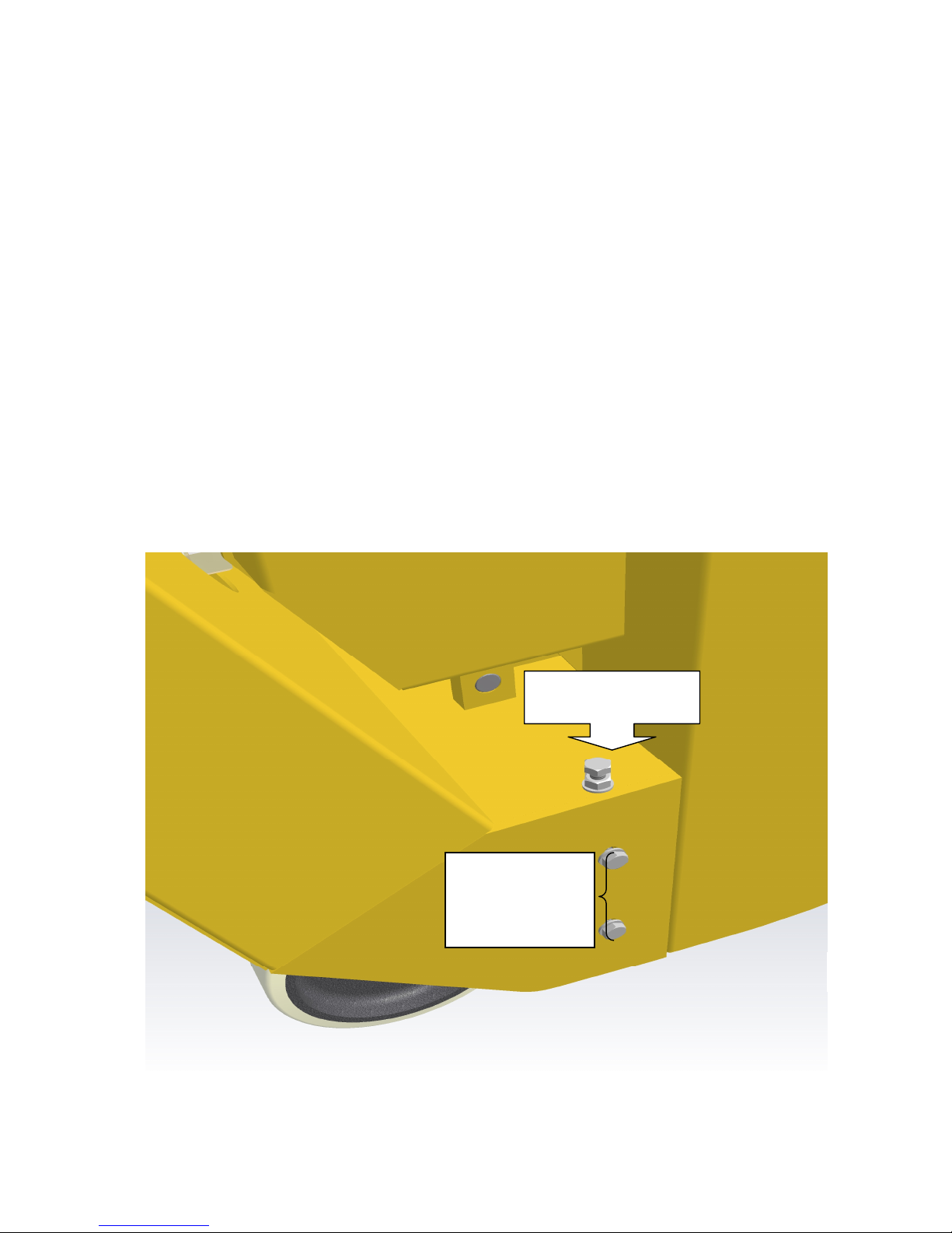
Should the machine be cutting more heavily on one side. Stop engine. Adjust
lock/nut bolt assembly on top of right hand side of chassis. By adjusting up or down
the cutting action can be reset level again. Retighten all bolts. Test on sample area
and if required reset until cutting correctly.
Great care should be taken to ensure belts have correct tension and also correct
alignment. Serious damage could be caused to the drive shaft, drive shaft bearings
and engine if the belts are excessively tight.
Note: Never operate the BEF320 without belt guard fitted
5
Level Adjustment
bolt and lock nut
Slacken before
adjusting.
Tighten before
use.
Page 8

BASIC MAINTENANCE/CHECKLIST
DAILY: (or every 8hrs to 10hrs)
Check cutters
Check flail shafts
Check all bolts and nuts for tightness
Check belt tension
Clean air filter elements
Check engine oil
Check hydraulic oil level.
Clean any debris from drum enclosure and ensure drum turns freely.
See engine manufacturers maintenance details before start engine.
WEEKLY:
All the above with following:Grease all moving parts on height adjustment mechanism
Remove side plate
Check drum/bushes
Check side plate bearing
Check drive bushes
Check drive shaft
Check support wheels
Check hydraulic drive system
MONTHLY:
All the above with following:Change hydraulic oil
Strip down fully winding mechanism
Clean all threads and re-grease
Replace air filter elements
Page 9

SAFETY
Only trained operatives should be allowed to work the BEF320.
All operatives should wear ear defenders, goggles and an effective dust mask.
Note: It is possible that the noise level produced by the BEF320 could exceed
90dbA. Personal noise protection must be worn.
To control dust it is recommended that an SPE dust control unit/vacuum is fitted.
Never leave the BEF320 unattended while in use. Always stop the engine and set
the height adjustment fully up before leaving the machine.
Never remove the side plate or belt guard until the cutter drum has come to a
complete standstill. Never tip the machine backwards until the cutters have come to
rest.
Never operate the BEF320 inside or in a poorly ventilated area. Carbon monoxide
gas is emitted..
Noise and vibration will occur at various levels dependant on the attachments and
work being completed. SPE have assessments conducted under test conditions
detailed in the operating manual. (See page 24). However it is recommended that
additional tests are taken on site to provide the operator with accurate information on
using the equipment within the guidelines laid down by the Health & Safety
Executive.
Page 10
ACCESSORIES
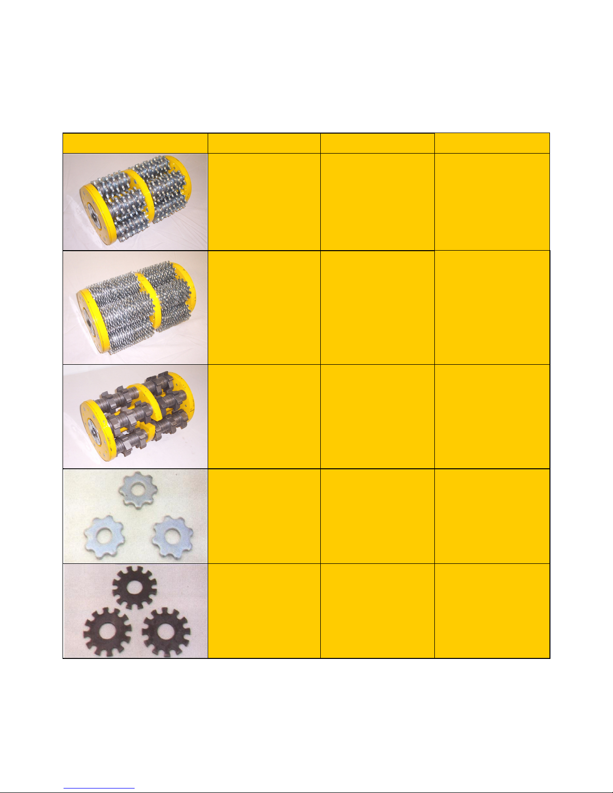
Part number Description Application
32001
Heavy duty drum complete with
T.C.T. cutters and spacers.
Hardened steel cutter with
tungsten inserts, for all concrete
texturing, scabbling, planing and
grooving applications. Removal of
bridge deck and car park
membranes, heavy industrial
contamination, epoxy coatings and
road markings. Use on heavy
applications for longer life and
higher output.
32002
Heavy duty drum complete with
beam flails
Heat treated steel cutter for the
removal of paint coatings and
laitence from new floors. Also
used for removing of grease build
ups, dirt and ice deposits, keying
and light scabbling of concrete
when a "fine textured" surface is
required.
32003
Heavy duty drum complete with
milling cutters and spacers.
For the removal of thermoplastic
road/runway markings. Very
efficient and cost effective with
none of the problems associated
with burning off thermoplastics.
Also for removal of bituminous
materials and rubber deposits.
80800
T.C.T. Cutter: 8 point hardened
steel cutter with tungsten carbide
insert.
For all concrete texturing
scabbling, planing and grooving
applications. Removal of bridge
deck and car park membranes,
heavy industrial contamination,
epoxy coatings and road
markings. Use on heavy
applications for longer life and
higher output.
80120
Beam cutter: Heat treated steel
cutter.
For the removal of paint coatings
and laitence from new floors. Also
used for the removing of grease
build ups, dirt and ice deposits,
keying and light scabbling of
concrete when a "fine textured"
surface is required.
7
Page 11
ACCESSORIES
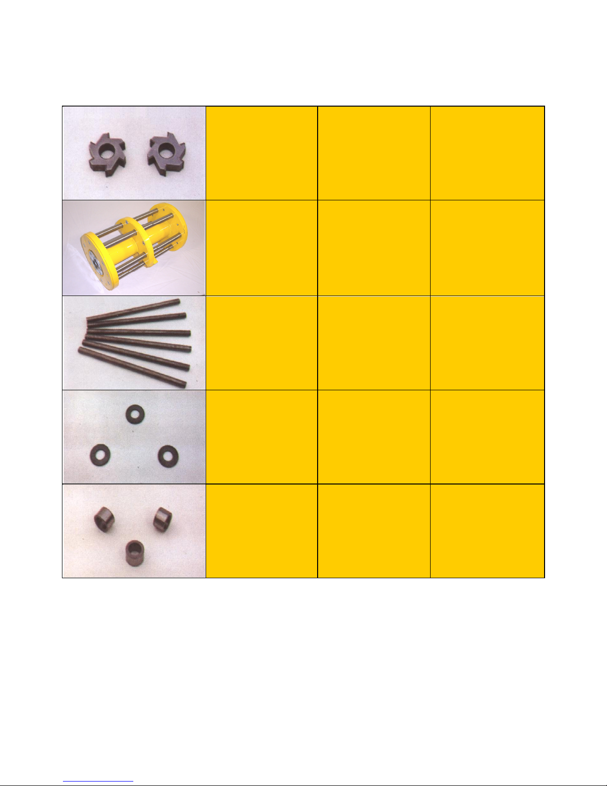
20mm
80600N
Milling cutter: Tipped with
tungsten carbide.
For the removal of thermoplastic
road/runway markings, rubber
based deposits and cold plastic
coatings from asphalt and
concrete.
32000
Heavy duty drum complete with
flail shafts.
For use with various cutter
configurations.
32020
Heavy duty flail shaft. Hardened cutter shaft.
40240
Spacing washer. Hardened spacing washer.
3049
Hardened Bush.
Hardened drum inserts to carry
flail shafts.
Page 12
12
Page 13
SPECIFICATION SHEET
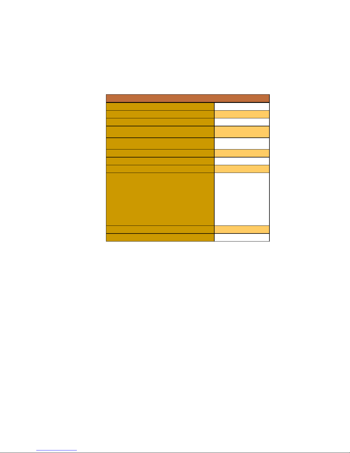
Specifications
Type
Diesel
Part Number
BEF320-3A
Power Output (hp)
10
Voltage
Cycles
Cutter head speed (rpm)
650
Starter
Manual
Travel speed mtr/min
0-12
Machine Dimensions (mm)
Length
Width
Height
Weight (kg)
c/w cutter drum
1230
590
1220
319
Working wid
th of cutters (mm)
320
Working distance from wall (mm)
40
23
Page 14
RECORD OF NOISE AND VIBRATION ASSESSMENT
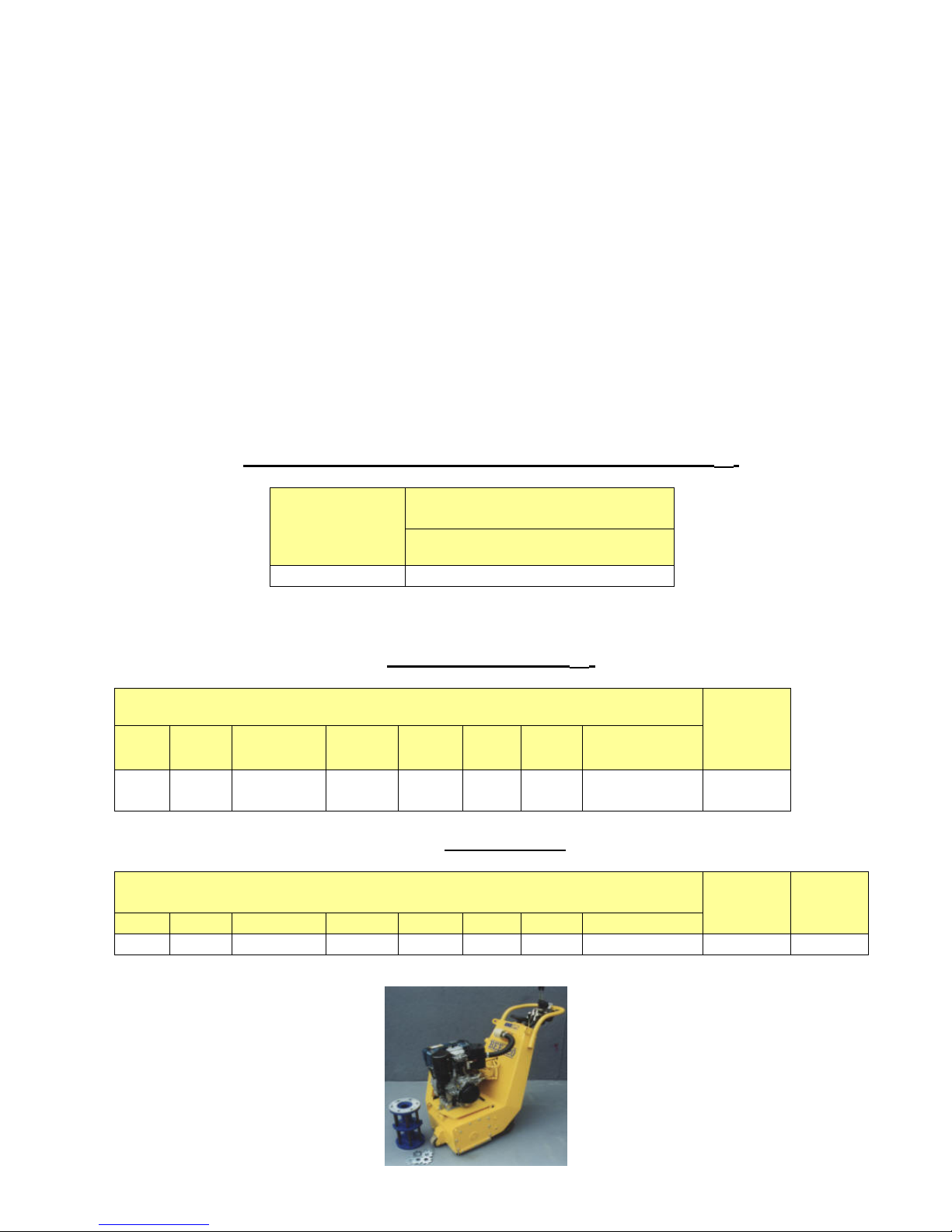
Manufacturer:
Type: Scarifier
Model No. BEF 320-3A Diesel
Motor: Yanmar
Operation : Concrete floor surface
Inserted Tool: TCT cutters
Running Conditions: 1800 rpm
HAV Note: Acoustic Associates
HAND
-
ARM VIBRATION
Frequency Weighted Energy Equivalent Accelerations (a
h,w
)
Measurement
Position Acceleration (m/s2)
Vector Sum
Handle 7.805
NOISE LEVELS
Sound Power Level (L
WA
)
LWA at Octave Band Centre Frequency (Hz)
S
ound
Power
Level
LWA
63 125 250 500 1000 2000 4000 8000
83.8 94.1 98.6 105.4 106.9
105.
3 101.0
94.8 111.6
Operator's Ear
L
Aeq,T
at Octave Band Centre Frequency (Hz)
Overall
Level
(L
Aeq,T
)
L
Peak
dB(C)
63 125 250 500 1000
2000
4000
8000
68.6 77.5 81.3 91.6 93 89.3 85.5 79.2
96.3
111
24
 Loading...