

Page 1
INSTALLATION, OPERATING
AND MAINTENANCE INSTRUCTIONS
DERV(DX/CHW)
C/W CHILLED WATER AND SPLIT SYSTEMDX COOLING
QA/IOM/63 ISSUE 2 – DERV
UNITS
Page 2

1 General Description
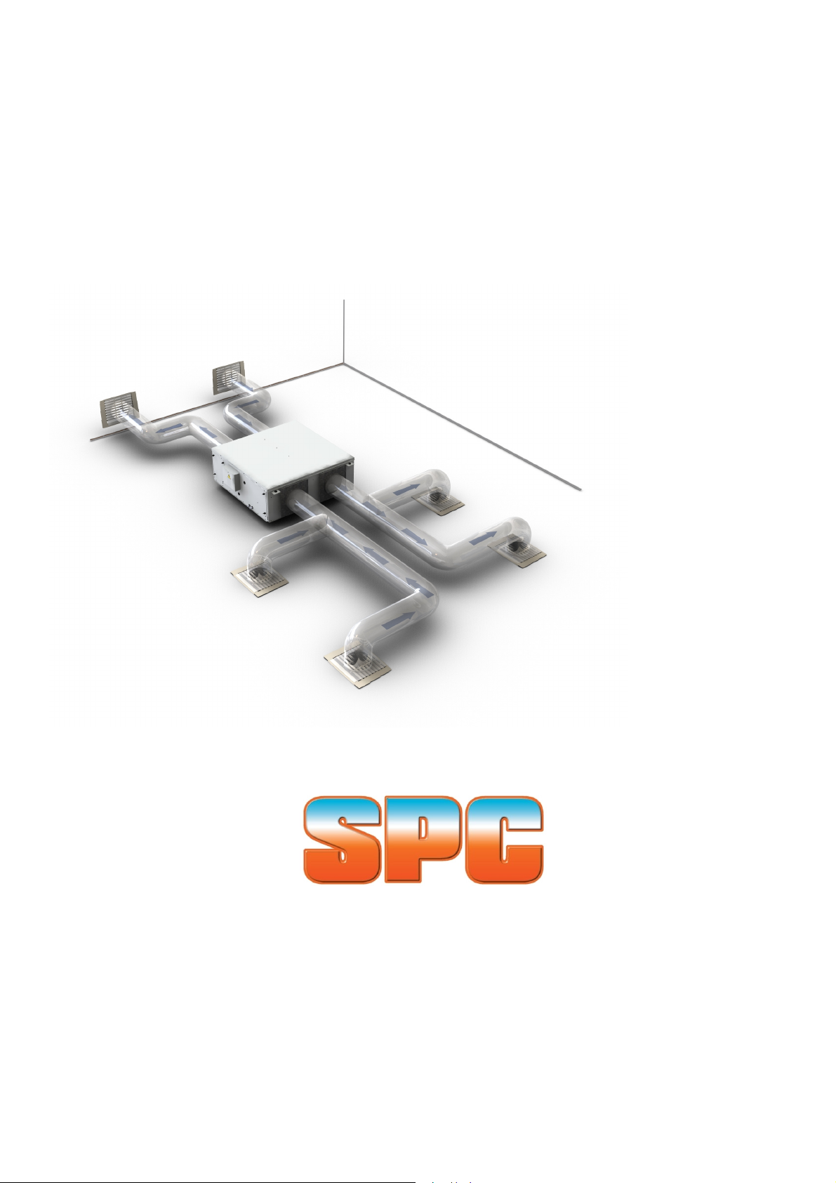
SPC DERV(DX/CHW) units are heat recovery ventilator units incorporating heat recovery heat
pipes, dehumidifier heat pipes and an active DX cooling coil or chilled water cooling coil. DX units
are supplied with a matched condensing unit for external mounting and for piping to the DERVDX
unit which acts as the indoor unit in the split system.
The units are intended to fully condition outside air by taking advantage of the cooling potential of
dirty extract air and the cooling and dehumidifying potential of a DX evaporator coil or chilled
water cooling coil.
The units are constructed in two halves; one half incorporating the extract fan(s) and extract
section of the heat recovery heat pipe, the other half contains the supply fan(s), supply section of
the heat recovery heat pipe plus chilled water/DX cooling coil c/w heat pipe wrapped around it.
The wrap around heat pipe precools the air prior to the cooling coil and reheats it after the cooling
and dehumidifying process to generate neutral ventilation air.
Units incorporate filtration on both the supply and extract side and are designed to be mounted
out of sight above false ceilings, suspended from the ceiling slab.
The supply and extract sections terminate in sheet metal flanges for the attachment of ducting.
Ducting design will be to suit the desired distribution within the premises and is largely beyond the
scope of this manual.
Units are supplied with an on/off and three speed controller to control the rotational speed of the
backward curved centrifugal fans and hence control the throughput of air on both the supply and
extract side. Further control of the air throughput must be made as part of the ducting design with
branch sizes matched to air volumes and manual volume control dampers fitted where
necessary. DX versions supplied with matched outdoor units incorporate a relay for switching of
the compressor and an additional temperature setting switch.
2 Technical Details
The table below gives details of the nominal operating characteristics of the DERV units along
with pertinent weights and dimensions. Operating limits for the units are as follows:
Maximum outside air temperature: 55°C
Minimum outside air temperature: 5°C
Maximum extract air temperature: 40°C
Minimum extract air temperature: 5°C
Units should be installed in a non-condensing environment.
Minimum outside air temperature for condensing unit operation of DX model: 20°C
QA/IOM/63 ISSUE 2 - DERV Page 2 of 19
Page 3
DERV chilled water units
Unit size 80 150 250
Nominal supply volume (litres/s) 107 155 236
Nominal extract volume (litres/s) 107 155 236
Nominal supply external static (Pa) 80 80 80
Nominal extract external static (Pa) 80 80 80
Total net cooling (W) 6375 9788 15127
Sensible cooling (W) 3313 4929 7561
Cooling coil total capacity (W) 5150 7779 11462
Supply air dry bulb (°C) 20.2 19.5 19.3
Supply air wet bulb (°C) 17.1 16.0 15.7
Heat recovery heat pipe cooling load saving (W) 1225 2009 3665
Wraparound heat pipe precool load saving (W) 622 1040 1660
Wraparound heat pipe reheat load saving (W) 622 1040 1660
Power supply (V/Ph/Hz) 230/1/50 230/1/50 230/1/50
Nominal current draw (A) 0.6 1.0 1.7
Nominal power draw (W) 138 230 391
Weight (kg) 75 100 130
Water flowrate (litres/s) 0.22 0.33 0.51
Water pressure drop (kPa) 10 9 18
Coil inlet connection size (mm) 15 22 22
Coil outlet connection size (mm) 15 22 22
The conditions upon which the above data is based are as follows:
Outside air @ 46/30°C
Extract air @ 25°C
CHW flow/return @ 7.2/12.8°C
500
473
473
80
80
30310
15155
23970
19.3
15.7
6340
3320
3320
230//1/50
3.4
782
190
1.02
19
28
28
QA/IOM/63 ISSUE 2 - DERV Page 3 of 19
Page 4
DERV DX version
Unit size 150 250
Nominal supply volume (litres/s) 155 236
Nominal extract volume (litres/s) 155 236
Nominal supply external static (Pa) 80 80
Nominal extract external static (Pa) 80 80
Total net cooling (W) 9788 15127
Sensible cooling (W) 4929 7561
Supply air dry bulb (°C) 19.5 19.3
Supply air wet bulb (°C) 16.0 15.7
Cooling coil total capacity (W) 7779 11462
Heat recovery heat pipe cooling load saving (W) 2009 3665
Wraparound heat pipe precool load saving (W) 1040 1660
Wraparound heat pipe reheat load saving (W) 1040 1660
Power supply (V/Ph/Hz) 230/1/50 230/1/50
Nominal current draw (A) 1.0 1.7
Nominal power draw (W) 230 391
Weight (kg) 100 130
Suction connection (“) 7/8 7/8
Liquid connection (“) 3/8 3/8 5/8 5/8
Outdoor unit power supply (V/Ph/Hz) 230/1/50 230/1/50 400/3/50 400/3/50
Outdoor unit nominal power draw (A) 13.1 18.0 8.4 8.4
Outdoor unit nominal power draw (W) 3013 4140 4143 4143
Compressor Reciprocating Reciprocating Scroll Scroll
Refrigerant R22 R22 R22 R22
Expansion device Capillary Capillary Valve Valve
Outdoor unit size WxHxD (mm) 1020x954x406 1020x954x406 1020x1270x406 1020x1270x406
Outdoor unit weight (kg) 80 90 110 120
375 500
358 473
358 473
80 80
80 80
22907 30310
11470 15155
19.3 19.3
15.7 15.7
18125 23970
4782 6340
2504 3320
2504 3320
230/1/50 230/1/50
2.0 3.4
460 782
170 190
1,1/8 1,1/8
The conditions upon which the above data is based are as follows:
Outside air @ 46/30°C
Extract air @ 25°C
Table1: Technical data
QA/IOM/63 ISSUE 2 - DERV Page 4 of 19
Page 5
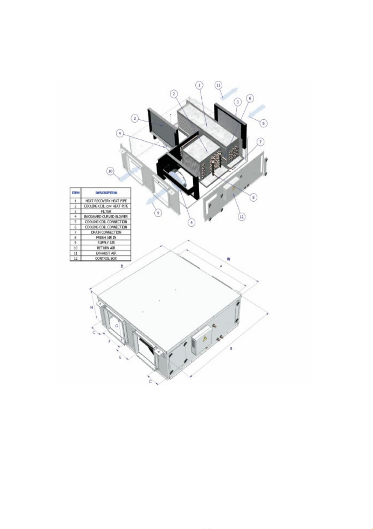
Detailed unit dimensions and construction information is highlighted on the figure below:
igure 1: Physical unit data
F
Outdoor unit sizes for DERVDX models are given in the performance table above.
QA/IOM/63 ISSUE 2 - DERV Page 5 of 19
Page 6

3 Reception & storage
DERV units are delivered in purpose made cardboard containers, if ordered as a DX version with
outdoor unit then this will be packaged separately. Upon receipt of the units the packaging should
be checked for any obvious damage and the labeling checked against the project requirement.
Any damage or delivery discrepancy should be reported to the SPC local office immediately. After
checking the packaging the units should be removed and a visual inspection carried out and any
damage reported immediately. If the units are not to be installed immediately then they should be
returned to the packaging for storage.
It is recommended that the units be stored in a safe location away from site activity and they must
not be exposed to the ambient. Units must be stored in non-condensing atmospheres where
temperatures cannot exceed 50°C.
4 Installation
4.1 Mounting of Indoor Unit
DERV and DERVDX indoor units must be installed horizontally and are intended to be fitted in a
concealed location, ideally above a false ceiling. The units must be suspended from the concrete
ceiling slab or other fixed and firm horizontal steelwork. Care must be taken to ensure that the
DERV(DX) unit is fixed to a structure that will accept the unit weight as shown in the above table
and that vibrations are not transmitted.
DERV(DX) units are supplied with 4-off robust fixing lugs at each of the corners of the unit (6-off
on the size 500). Each of these lugs incorporates a rubber bush to prevent unit vibrations being
directly transmitted to the mounting/support rods. The units should be mounted from the
ceiling/steelwork using threaded drop-rods. These drop-rods are not supplied with the units but
we recommend the use of M8 threaded rod.
The ceiling or support structure should first be marked out to match the position of the holes in
the DERV(DX) unit fixing lugs. The structure should then be drilled and fitted with suitable
anchors capable of accepting the weight of the DERV(DX) unit. Brackets can then be secured to
the ceiling anchors for securing the threaded drop rods. The rods should be cut to length and
secured to the ceiling bracket or supporting steelwork and the other end passed through the fixing
lugs on the DERV(DX) unit.
The drop-rods should be secured with suitable nuts on either side of the fixing lugs around the
anti-vibration bushes. It is important that the unit is fitted level in both directions so that correct
operation and drainage are ensured. A maximum deviation of 3mm from the horizontal should be
maintained and checked on installation using a spirit level and adjusted using the retaining nuts
on the fixing lugs.
4.2 Mounting/Location of Outdoor Unit (DERVDX only)
Outdoor units supplied with DERVDX are suitable for floor mounting and are side discharge
models. It is important that there is no obstruction on the air inlet and outlet sides of the unit and
that there is no possibility of hot discharge air being drawn back into the inlet.
QA/IOM/63 ISSUE 2 - DERV Page 6 of 19
Page 7

A minimum clearance of 600mm must be ensured on all sides of the unit except the air discharge
side where the clearance must be a minimum of 1500mm.
The unit must be located outside and must not be ducted. Ensure that the unit is not subject to
direct sunlight and cannot be subjected to any water run-off.
The unit must be mounted on a flat horizontal surface where vibrations cannot be transmitted to
the building structure and securely fixed.
A location should be found whereby the length of refrigerant pipes between the outdoor unit and
the indoor DERVDX unit is minimized.
4.3 Refrigerant Piping (DERVDX only)
The detailed instructions regarding the refrigerant piping given in the condensing unit IOM manual
should be followed. The text below gives general guidance. All refrigeration pipework should be
undertaken by a suitably qualified refrigeration engineer.
4.3.1 Liquid/Vapour lines
The table below identifies the recommended liquid and vapour line sizes based on the size of
DERVDX unit being installed. All refrigeration piping should be clean, dehydrated refrigeration
grade copper and should remain sealed until ready for use. A filter drier and liquid sight glass
may be installed in the liquid line upstream of the expansion device.
Unit size Liquid line OD Vapour line OD
DERVDX 150
DERVDX 250
DERVDX 375
DERVDX 500
Table 2: Recommended refrigerant line sizes.
Both vapour and liquid lines should be insulated to prevent sweating and performance reduction.
A minimum of ½” thick pipe insulation should be used. In order to avoid any reduction in
performance it is recommended that the maximum distance between indoor and outdoor unit
(including any vertical lift) be limited to 15m.
Whenever tubing is cut it should be carefully deburred so as to prevent any chips falling into the
tubing to be used. Any bends in the pipework should be made using proper tube bending
equipment so as to prevent any kinking.
Wherever possible tube connections should be of the sweat type and made using copper brazing
material. For copper to copper brazing up to 5% silver content brazing rods should be used, for
copper to brass or steel then 35% silver content is recommended. Tubing and fittings should be
cleaned with wire wool prior to brazing and any debris prevented from entering the pipe. When
brazing at or near to the service valves the caps and Schraeder cores should be removed to
prevent damage and the valves themselves covered in wet rags. A flow of nitrogen should be
directed through a service port and tubing while brazing.
If flare joints are to be used these must be properly made ensuring the following:
3/8” 5/8”
3/8” 7/8”
3/8” 7/8”
1/2” 1,1/8”
QA/IOM/63 ISSUE 2 - DERV Page 7 of 19
Page 8

• No thinning of the flare tube material
• No cracked or split tubes
• No longitudinal scoring or tool marks
• Correct torque setting used to match diameter of nuts
After having completed the pipework the system should be pressure tested to ensure that there
are no leaks. Dry nitrogen up to a maximum pressure of 10 bar should be used and all joints
should be tested using leak detection spray or detergent.
4.3.2 Coil connections
For DERVDX size units 150 and 250 the evaporator coil in the indoor unit is equipped with a
capillary type expansion device. This device is factory brazed onto the coil within the casing of the
indoor unit. The liquid and vapour connections terminate outside the casing of the unit and are
sealed; the coil contains a holding charge of nitrogen which should be heard escaping when the
connections are opened with a hole cutter.
For unit sizes 375 and 500 the indoor units are supplied with a loose thermostatic expansion
valve. The valves must be fitted outside the casing of the unit and should be installed in line with
the instructions supplied with the device. When brazing the TEV into the liquid line it is important
that the valve is protected using wet rags so as to avoid any damage to same. The TEV should
be fitted as close as possible to the liquid connection on the coil.
4.3.3 Evacuation
After leak testing, the pipework should be evacuated before any of the valves are opened. The
vacuum pump should be connected to both the high and low side of the system and a deep
vacuum drawn to 500 microns. Triple evacuation is recommended if the vacuum pump cannot
achieve such deep vacuum levels.
4.3.4 Refrigerant charge
The outdoor unit is shipped with sufficient refrigerant for operation of the system with up to 5m
liquid line distance between the indoor and outdoor unit. The required system charge will be
indicated on the charging chart inside the access cover of the outdoor unit.
If the length of the liquid line exceeds 5m then additional charge should be added according to
the diameter of the liquid line. For 3/8” diameter pipe refrigerant should be added at a rate of 60
grams/metre and for ½” diameter pipe at a rate of 120 grams/metre.
If the unit is supplied without refrigerant or the refrigerant recovered and the whole system
evacuated then the full charge as shown on the charging table will need to be added.
4.3.5 Oil traps
To ensure adequate oil return to the compressor it is recommended that oil traps be fitted with at
least one trap for every 3m of vertical height. When the outdoor unit is above the indoor unit the
traps should be fitted in the suction line, if the indoor unit is above the outdoor unit then the traps
need to be fitted in the liquid line.
QA/IOM/63 ISSUE 2 - DERV Page 8 of 19
Page 9

4.4 Electrical connections
4.4.1 DERV units
DERV units are designed to allow simple operation with the minimum of electrical power and
control wiring required on site. A wiring diagram for the unit is attached to the unit next to the
terminal block. A copy of the wiring diagram is shown below.
Figure 2. Wiring details DERV units
For the size 500 unit the fuse rating is 5A not 2A as shown above.
Power supply to the units is single phase 230V/50Hz. A three wire supply is required (PH/N/E)
and this should be taken from a suitably isolated power supply. Maximum running current and
power drawn are given in the technical data table but minimum wire size for the power supply
should be 1mm2.
The terminal block is accessible on the side of the indoor unit. The 3-core power cable should be
connected to this terminal block as shown on the wiring diagram attached to the unit.
The DERV units incorporate a built-in controller allowing the speed to be changed (speed 1,2 & 3)
along with an on/off switch. Provision has also been made for remote control of the DERV units
via two volt free contacts. These contacts can be used to switch the units on and off remotely via
switches or relays attached to BEMS, occupancy sensors etc. The two remote contacts are wired
into terminals R1/R2 and R3/R4 respectively. Again wire should be a minimum of 1mm2 and
remote contacts should be rated at a minimum of 2A (5A, 500 unit).
If one or both of the remote contacts are not used then links must be fitted between R1/R2 and
R3/R4.
QA/IOM/63 ISSUE 2 - DERV Page 9 of 19
Page 10

4.4.2 DERVDX units
DERVDX units are designed to allow simple operation with the minimum of electrical power and
control wiring required on site. A wiring diagram for the indoor unit and interconnection to the
outdoor unit is attached to the indoor unit next to the terminal block. A copy of the wiring diagram
is shown below.
Figure 3. Wiring details DERVDX units
While all indoor units use a single phase supply the outdoor units for the larger models, size 375
and 500 are three phase as shown above.
For the smaller single phase units (150, 250) a three wire supply is required (PH/N/E) and this
should be taken from a suitably isolated power supply. Maximum running current and power
drawn are given in the technical data table but minimum wire size for the power supply should be
1mm2. Both the indoor and outdoor units must be earthed and the power cables should be taken
from the terminal block of the outdoor unit to the indoor unit terminal block.
QA/IOM/63 ISSUE 2 - DERV Page 10 of 19
Page 11

The larger three phase units (375, 500) require cables for each of the phases and a neutral. Both
indoor and outdoor units must be earthed and a phase and neutral cable must be taken from the
3 phase terminal block in the outdoor unit to the indoor unit.
Two control wires must be run between the terminals on the controller of the indoor unit and the
relay terminals on the outdoor unit. It is recommended that these wires be a minimum of 1mm2.
The DERVDX units incorporate a built-in controller allowing the speed to be changed (Low, Med
& High) along with an on/off switch, see figure below. Provision has also been made for remote
control of the DERV units via two volt free contacts. These contacts can be used to switch the
units on and off remotely via switches or relays attached to BEMS, occupancy sensors etc. The
two remote contacts are wired into terminals R1/R2 and R3/R4 respectively. Again wire should be
a minimum of 1mm2 and remote contacts should be rated at a minimum of 2A (5A, 500 unit). If
one or both of the remote contacts are not used then links must be fitted between R1/R2 and
R3/R4.
The controller is connected to a thermistor sensor located between the heat recovery heat pipe
and the dehumidifier heat pipe inside the indoor unit and senses the temperature at this point.
The three temperature settings available equate to 22, 24 and 26°C respectively, when the
sensed temperature falls below the set temperature then the outdoor unit will switch off. It is
recommended that the lowest temperature setting is used to provide continuous operation of the
outdoor unit.
The controller incorporates a built in time delay on the compressor to prevent hunting and has a
non-volatile memory allowing the settings to be saved.
Figure 4. Controller display
When the compressor delay timer is operating the set temperature LED will blink on and off for
half a second each. The on delay timer is set at 180 seconds.
When the compressor is not running according to the temperature setting the LED blinks on for
0.1 seconds and off for 0.9 seconds.
The compressor is set to run if the sensed temperature >= to the set temperature+1 and set to off
if the sensed temperature < set temperature.
QA/IOM/63 ISSUE 2 - DERV Page 11 of 19
Page 12

The variable indoor unit fan speed is achieved using phase angle control. When the phase angle
is changed the RMS value of the voltage at the fan motor is changed and hence the fan speed.
When the input AC Voltage is 230 V, 50 Hz the following voltage is applied at the fan motor.
Fan Speed AC Voltage applied at fan motor
Low 195 V
Medium 205 V
High Input AC voltage
Table 3: Fan speed details
If there is a thermistor fault this will be indicated on the display by flashing of all the cooling LEDs
and remote on/off by flashing of the fan speed LEDs.
4.5 Drain connection piping
The DERV(DX) units incorporate two internal draintrays; one beneath the heat recovery heat pipe
and one beneath the cooling coil/heat pipe section. There is an individual drain pipe extending out
from the side of each drainpan. These drainpipes are 30mm diameter plastic and must be
properly trapped in order to ensure than condensate is not held within the unit. The drainpans are
both on the suction side of the supply fan and subject to negative pressure and if not fitted with
drain traps will draw air into the unit and prevent the release of moisture. As these two drain
points are adjacent to one another and subject to very similar levels of vacuum it is permissible to
join the two together prior to the trap.
Suction pressures at the inlet to the supply fan can be as high as 200Pa depending on the
external resistance of the systems and traps should be sized to cope with this level of pressure.
Incorporating a safety factor to account for the effect of dirty filters etc, the required minimum
dimensions are shown in the diagram below.
QA/IOM/63 ISSUE 2 - DERV Page 12 of 19
Page 13

Figure 5. Trap dimensions
The minimum value for H should be 40mm which represents an equivalent water column height
of 400Pa.
Traps should be regularly inspected, particularly after periods of inoperation, to ensure that they
are not dry.
Immediately downstream of the drain trap there should be an air break to prevent any back
pressure. From this point the drain piping should either slope to waste or a condense pump
should be included. As the drain piping contains cool condense it should be insulated to prevent
sweating.
4.6 Ductwork connections
DERV(DX) units are complete with four rectangular spigots; two for the supply air and two for the
extract air. The spigots are sized to give a resultant velocity which is sufficiently low as to allow air
distribution through ducting or direct to diffusers without transformation of the duct size.
The ducting can be transformed to a smaller size after the outlet spigot and can be transformed to
circular ducting if this is preferred. A single DERV(DX) unit can be arranged to take its extract air
from one or more sources and its supply ducting can be arranged to supply one or a number of
different areas. Extract and supply grilles and diffusers should be used in line with good air
distribution practice.
Duct sizes should be selected to maintain an air velocity of less than 5m/s in all main ducts and
branches. This will not only minimize the external static pressure that the unit is operating against
but will also eliminate any noise problems. If the ducting runs through areas subject to high
humidity then the ducting should be lagged to prevent moisture formation, this is particularly
important for the supply ducting from the DERV(DX) unit which will be carrying cool air at around
20°C. Supply diffusers should be fitted with plenum boxes to reduce the velocity of the air before
introducing it to the occupied space.
If designing against a maximum duct velocity of 5m/s than a good approximation to the pressure
drop associated with the straight ducting is 2Pa/m. Fittings, branches, bends and grilles offer
additional dynamic resistances due to momentum changes of the air flow. A reasonable
approximation is to sum the number of the above fitting losses and allow 5 Pa for each. The
above will allow duct sizes to be reasonably approximated but the final design should be
undertaken by a designer/installer qualified in duct design and space air diffusion.
It is recommended that manually operated butterfly dampers are incorporated in the final branch
of all duct connections. This will simplify the commissioning process and provide the facility for
accurately setting the airflows to and from each zone. Without the use of dampers the air volumes
from each zone will only vary with the length and diameter of the ducting runs.
5 Operation
DERV(DX) units are supplied with a speed controller, on/off switch and the possibility to
incorporate remote contacts to switch the units on and off. The above controls vary the
throughput of air by varying the power supply to the fans. The units incorporate two-off fans; one
for the supply air and one for the extract air (375 and 500 units have two pairs of fans). In
QA/IOM/63 ISSUE 2 - DERV Page 13 of 19
Page 14

addition, DERVDX units are supplied with a matching condensing unit and are interconnected via
two wire control of the compressor relay.
For DERVDX units with crankcase heaters it is not recommended that the units are turned off by
disconnecting the mains. On/off control should be via the controller and remote contacts.
The units will have been selected to provide a particular supply and extract air volume; these will
be equal for a balanced ventilation application. If the area is to be pressurized then the supply air
volume will be higher than the extract and vice versa if the space is to be kept under negative
pressure.
The respective air volumes must be set by both adjusting the fan speed on the controller located
in the unit electrical box and manual adjustment of damper blades in the ducting. The speed of
the fans can be adjusted between speeds 1, 2 and 3 and the power supplied to the fan motors is
then controlled by the phase angle controller which varies the RMS value of the voltage. This
controller provides the same voltage to both supply and extract fans so the speed selection
switch should be used to achieve just in excess of the required air volume through the least
favoured leg of ducting. Accurate balancing of the air distribution system should then be carried
out by adjustment of the dampers.
The units can be put into operation by simply switching the on/off switch in the control box but
under normal circumstances this would be inaccessible to users. More obvious control
possibilities are to break the supply to the units via a switched fuse spur box or to take advantage
of the remote contacts provided. These contacts are discussed in the installation section and
allow on/off control of the units via switched contacts (manual switching or via relay). If the units
are to be controlled from a central system or BEMS then the requirement for ventilation should be
sensed via occupancy or carbon dioxide sensors.
DERVDX units have their outdoor units controlled by a temperature sensor connected to the
indoor unit controller; when the sensed temperature drops below the set point the compressor is
switched off as no further cooling of the ventilation air is required.
DERV units require a supply of chilled water to achieve the necessary dehumidification of the
ventilation air. The correct flowrate and flow temperature will be documented with the quotation
documents for the project. If these are unavailable then the values given in the technical data
table can be used. To ensure that the chilled water arrives at the cooling coil connections ensure
that all isolating valves are open and that the coil has been properly vented through the vent plug
provided. The pump system for the DERV units should be sized against the total flowrate for the
units and the waterside resistance figures with due consideration given to additional losses
associated with pipework, fittings and other flow regulating valves. All valving and control of the
chilled water flow is by others but it is recommended that the flow of chilled water bypasses the
DERV unit when the outside temperature drops considerably below the space temperature.
Under normal operating conditions the DERV(DX) units will generate considerable amounts of
condensed moisture. This must be adequately trapped and run to waste as described in the
installation section above.
6 Maintenance
It is suggested that the DERV(DX) units should be maintained on a monthly basis so as to ensure
continued correct operation. The maintenance routine should involve the following:
Filter cleaning: The indoor units incorporate two filters; one on the extract air side and one on the
supply air side. Access is provided for filter withdrawal from the sides of the unit via the slimmer
QA/IOM/63 ISSUE 2 - DERV Page 14 of 19
Page 15

removable panels on either side of the unit, held in place by wing nuts (see diagram above). After
removing the panel the filters can be slid out of the unit and cleaned using a vacuum hose or
pressure line. During cleaning the air should be drawn/blown through the filter in the opposite
direction to the operating airflow.
Airflow check: A check should be made to ensure that both the supply and extract fans are
operating. This can usually be ascertained by placing a hand over the supply/extract grilles within
the space. If there is no airflow through either the supply or the extract system then a further
investigation should be made. The fans and their associated wiring are accessible from either
side of the unit via the larger access panels which are released by unscrewing the wing nuts. Any
electrical servicing must be undertaken by qualified personnel after electrically isolating the unit.
Drain trap check: Drain trap(s) should be regularly checked to ensure that they are not dry and
that there is a liquid seal.
Indoor unit coil cleaning: The coil fin blocks should be regularly checked and cleaned with a soft
brush, vacuum or pressure hose to clear any debris from the surfaces. This will involve removal
of access panels and in some instances removal of the ducting attached to the spigots of the
DERV unit.
Indoor unit general cleaning: The outer casing of the DERV(DX) unit is finished in corrosion
resistant epoxy paint and can be wiped down with a wet cloth or with dilute cleaning agents.
DERVDX units are supplied with matching condenser units. The outer casing of the units should
be kept clean with a proprietary cleaner, the blades of the axial fan and the condenser coil should
also be regularly inspected/cleaned to ensure continued efficient performance.
If the condenser coil in the outdoor unit becomes contaminated by dirt, dust etc. then the system
performance will be reduced as the airflow is throttled; this leads to high operating pressures.
Before cleaning the condenser coil the power to the unit must be cut-off, material blocking the coil
can then be removed, manually, using compressed air or a water spray. If a spray is used it must
be directed from the inside of the casing to the outside in the opposite direction to normal airflow.
Ensure that the condensing unit is clean and dry before reconnecting the power, the unit should
then be left for several hours before switching on via the controller or remote contacts.
7 Fault finding
The tables below details faults that may occur, their cause and means of rectification
QA/IOM/63 ISSUE 2 - DERV Page 15 of 19
Page 16

Fault Cause Remedy
One fan does not
run
Both fans do not run Unit switched off Switch on at unit or remote
Low airflow Dirty filter Remove and clean
High airflow High speed selected Reduce speed setting
High supply air
temperature
Humid supply air No chilled water available Check chilled water supply
Moisture in supply
airstream
No moisture from
unit
Ductwork sweating Humid environment Insulate ducting
Pipework sweating Uninsulated piping Insulate all piping
Motor failure Replace faulty fan/motor
assemby
Loose wire Check integrity of wiring on
fan terminal
Capacitor burn-out Look for signs of damage
and replace capacitor
switch
Unit held off by remote
contact/switch
Power failure Check power supply to unit
Fuse blown Replace fuse
Loose wire Check and tighten
Low speed selected Increase speed setting
Ducting blocked Check dampers, grilles etc
Unbalanced ducting Check damper positions
No chilled water available Check chilled water supply
Chilled water flowrate too low Check position of valves and
Chilled water temperature too
high
Air trapped in coil Vent coil
Chilled water flowrate too low Check position of valves and
Chilled water temperature too
high
Air trapped in coil Vent coil
No drain trap fitted Fit drain trap
Drain trap dry Prime trap
Drain trap too small Increase trap height
No drain trap fitted Fit drain trap
Drain trap dry Prime trap
Drain trap too small Increase trap height
Check power at terminals
and remote contact signals
pump operation
Check chiller operation or
temperature of chilled water
supply
pump operation
Check chiller operation or
temperature of chilled water
supply
T
able 4. Fault finding DERV units
QA/IOM/63 ISSUE 2 - DERV Page 16 of 19
Page 17

Fault Cause Remedy
One indoor unit fan
does not run
Both indoor unit
fans do not run
Low indoor unit
airflow
High indoor unit
airflow
Insufficient cooling No chilled water available Check chilled water supply
Moisture in supply
airstream
No moisture from
unit
Ductwork sweating Humid environment Insulate ducting
Pipework sweating Uninsulated piping Insulate all piping
Outdoor unit does
not run
Outdoor fan runs,
compressor doesn't
Motor failure Replace faulty fan/motor
assemby
Loose wire Check integrity of wiring on
fan terminal
Capacitor burn-out Look for signs of damage
and replace capacitor
Unit switched off Switch on at unit or remote
switch
Unit held off by remote
contact/switch
Power failure Check power supply to unit
Fuse blown Replace fuse
Loose wire Check and tighten
Dirty filter Remove and clean
Low speed selected Increase speed setting
Ducting blocked Check dampers, grilles etc
High speed selected Reduce speed setting
Unbalanced ducting Check damper positions
Chilled water flowrate too low Check position of valves and
Chilled water temperature too
high
Air trapped in coil Vent coil
No drain trap fitted Fit drain trap
Drain trap dry Prime trap
Drain trap too small Increase trap height
No drain trap fitted Fit drain trap
Drain trap dry Prime trap
Drain trap too small Increase trap height
Loose connection Check terminal wiring
Thermostat not calling Check temperature setting
Defective contactor Check voltage at contactor
High pressure trip Reset
Start capacitor/relay
defective
Check power at terminals
and remote contact signals
pump operation
Check chiller operation or
temperature of chilled water
supply
coil
Replace
QA/IOM/63 ISSUE 2 - DERV Page 17 of 19
Page 18

Compressor short
cycles
High head pressure,
low vapour pressure
High head pressure,
normal vapour
pressure
Low head pressure,
high vapour
pressure
Low vapour
pressure, cold
compressor &
indoor coil
High vapour
pressure
Pulsing at
expansion device
Fluctuating
pressures
Loose connection Check compressor wiring
Compressor jammed or
motor winding open
Incorrect voltage Must be within 10% of
Defective overload protector Replace
Restriction in liquid line,
expansion device or filter
drier
Dirty outdoor coil Clean coil
Refrigerant overcharge Correct system charge
Outdoor fan not running Repair or replace
Air in system Recover, evacuate and
Defective compressor valves Replace
Low indoor unit airflow Increase speed of indoor
Excessive load Check load calculations
Defective compressor Replace
Air in system Recover, evacuate and
Air in system Recover, evacuate and
Wait for overload to reset (2
hours). Replace compressor
if necessary.
nameplate
Remove or replace
recharge
blowers or reduce restriction
recharge
recharge
Table 5. Fault finding DERVDX units
8 Spares
Spare filters, fans, coils and other components are available for DERV(DX) units. These can be
ordered with the units or subsequently. Please contact the local SPC office for details.
QA/IOM/63 ISSUE 2 - DERV Page 18 of 19
Page 19

SPC Heat Pipes FZC
PO Box 50816, Dubai, UAE
Tel: 0097143341178, Fax: 0097143341179
e-mail: spcoils@spcoils.ae Web: www.spcoils.ae
QA/IOM/63 ISSUE 2 - DERV Page 19 of 19
 Loading...