

Page 1
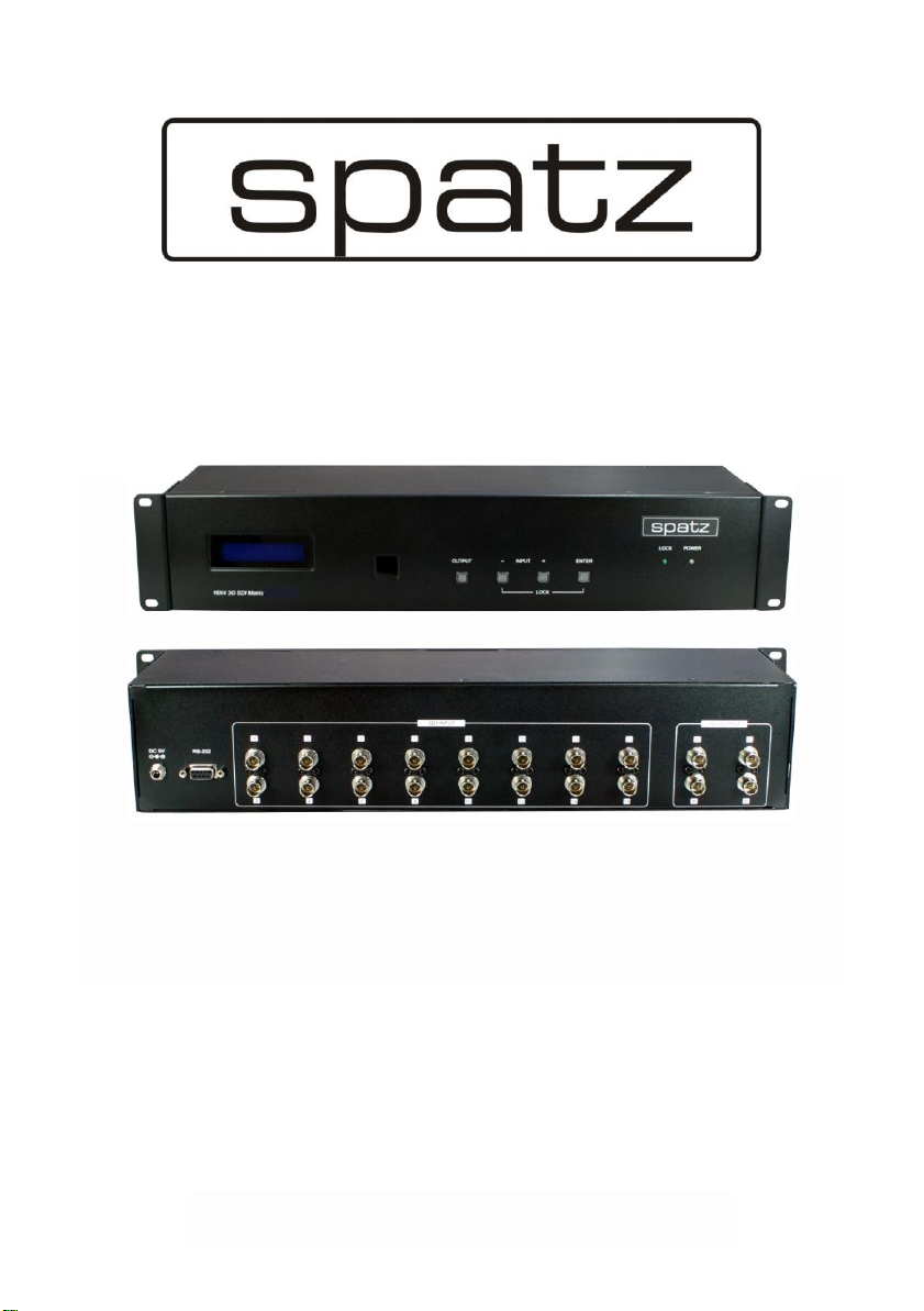
SDI-X164
O
O
O
p
p
p
e
e
e
r
r
r
a
a
a
t
t
t
i
i
i
o
o
o
n
n
n
s
s
s
M
M
M
a
a
a
n
n
n
u
u
u
a
a
a
l
l
l
16 by 4 3G-SDI Matrix
Page 2

DISCLAIMERS
The information in this manual has been carefully checked and
is believed to be accurate. SPATZ assumes no responsibility for any
infringements of patents or other rights of third parties which may
result from its use.
SPATZ assumes no responsibility for any inaccuracies that may be
contained in this document. SPATZ also makes no
commitment to update or to keep current the information contained
in this document.
SPATZ reserves the right to make improvements to this document
and/or product at any time and without notice.
COPYRIGHT NOTICE
No part of this document may be reproduced, transmitted,
transcribed, stored in a retrieval system, or any of its part translated
into any language or computer
electronic, mechanical, magnetic, optical, chemical, manual, or
otherwise—without express written permission and consent from
SPATZ Technology.
© Copyright 2012 by SPATZ. All Rights
Reserved.
Version 1.1 January 2012
file,
in any form or by any means—
TRADEMARK ACKNOWLEDGMENTS
All products or service names mentioned in this document may be
trademarks of the companies with which they are associated.
Page 3

SAFETY PRECAUTIONS
Please read all instructions before attempting to unpack, install or
operate this equipment and before connecting the power supply.
Please keep the following in mind as you unpack and install this
equipment:
• Always follow basic safety precautions to reduce the risk of
electrical shock and injury to persons.
• To prevent
moisture or install this product near water.
• Never spill liquid of any kind on or into this product.
• Never push an object of any kind into this product through any
openings or empty slots in the unit, as you may damage parts
inside the unit.
• Do not attach the power supply cabling to building surfaces.
• Use only the supplied power supply unit (PSU). Do not use the PSU
if it is damaged.
• Do not allow anything to rest on the power cabling or allow any
weight to be placed upon it or any person walk on it.
• To protect the unit from overheating, do not block any vents or
openings in the unit housing that provide ventilation and allow for
sufficient
fire
or shock hazard, do not expose the unit to rain,
space for air to circulate around the unit.
fire,
Page 4

CONTENTS
1. Introduction.............................................. 5
2. Applications ............................................. 5
3. Package Contents .................................. 5
4. System Requirements.............................. 5
5. Features .................................................... 5
6. Operation Controls and Functions......... 6
6.1 Front Panel ..........................................6
6.2 Rear Panel...........................................7
7. RS-232 Protocols ...................................... 8
7.1 Pin Assignment ...................................8
7.2 Commands .........................................8
8. Remote Control........................................ 9
9. Connection and Installation.................10
10. Specifications ...................................... 11
11. Acronyms ............................................. 11
Page 5

1. INTRODUCTION
The 16 by 4 3G-SDI Matrix allows SD-SDI, HD-SDI and 3G-SDI signals to
be shown on SDI displays while ensuring high bit rates of 2.970 Gbit/s
to give you fast signal transmission without signal loss. For professionals
this means that it is now easier to switch sixteen 3G-SDI signals and split
it up to four SDI signal outputs. Further, with remote, on panel keys and
RS-232 control functions, these ease users with multi-controls over the
device.
2. APPLICATIONS
• Video broadcasting switching display
• Professional video program display
• Film studios program monitoring
• Video program switching display
3. PACKAGE CONTENTS
• 16 by 4 3G-SDI Switcher
• Remote Control (CR-101)
• 5V/2.6A DC power adaptor
• Operation Manual
4. SYSTEM REQUIREMENTS
Input connects with SDI sources and output connects with SDI displays,
all input/output with SDI cables.
5. FEATURES
• Sixteen 3G-SDI input sources can be selected and split or switch to
four 3G-SDI displays simultaneously
• Operation at 2.970Gb/s, 2.970/1.001Gb/s, 1.485Gb/s, 1.485/1.001Gb/
s and 270Mb/s
• Supports SMPTE 425M (Level A and Level B), SMPTE 424M, SMPTE
292M, SMPTE 259M-C
• Integrated audio de-embedding for a maximum of 8 channels,
48kHz audio
Page 6
• Connect with other units to extend your signal over long distances
• Equalized and re-clocked
• Supports signal input and output distance of up to 300M for SD
signals, 200M for HD signals and 100M for 3G signals.
NOTE
Cable tested with Belden 1694A. Operating distances may vary if
used with another type of cable.
6. OPERATION CONTROLS AND FUNCTIONS
6.1 Front Panel
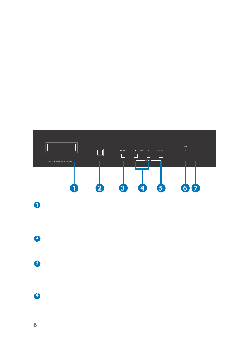
LCM Monitor
This LCM monitor display the input and output selection and the
upper line is displaying output A, B, C, &D where as the lower line is
displaying each output’s input selection.
IR receiver
This IR window receives IR signal from the remote control included
in the package.
OUTPUT Button
Press this button to select the output A~D the cursor will jump
on the lower line of the LCM monitor then, select a input for the
cursor’s pointed output.
INPUT -/+ Button
Press – or + button to select the input sources from 1~16, after the
selection press ENTER to
confirm
the option.
Page 7
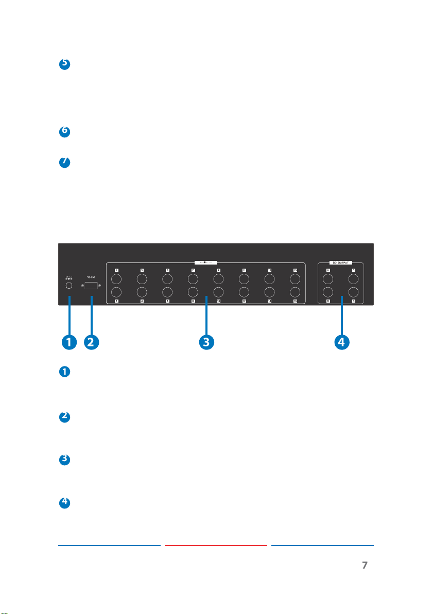
ENTER Button
Press this button to
key and – key together to lock all the keys on panel. To unlock,
press both the ENTER key and – key together again to release the
locking system.
LOCK LED
This LED will illuminate in green when the key lock is executed.
POWER LED
This green LED will illuminate when the device is switch to ON. Press
the power key from the remote control the device will switch to
standby mode and the LED will turn into red.
confirm
the selection. Press both the ENTER
6.2 Rear Panel
DC 5V
Plug the 5V DC power supply into the unit and connect the
adaptor to AC wall outlet.
RS-232
Connect the D-Sub 9pin’s cable from PC/NB for RS-232 control
signal sending to the device.
SDI INPUT
These slots are to connect to the SDI source equipments such as
video camera or SDI player.
SDI OUTPUT
SDI OUTPUT: These slots are to connect to the SDI displays with
an SDI cables for displaying images. Or it can be connect with
another SDI converter/extender to extend the signal
Page 8
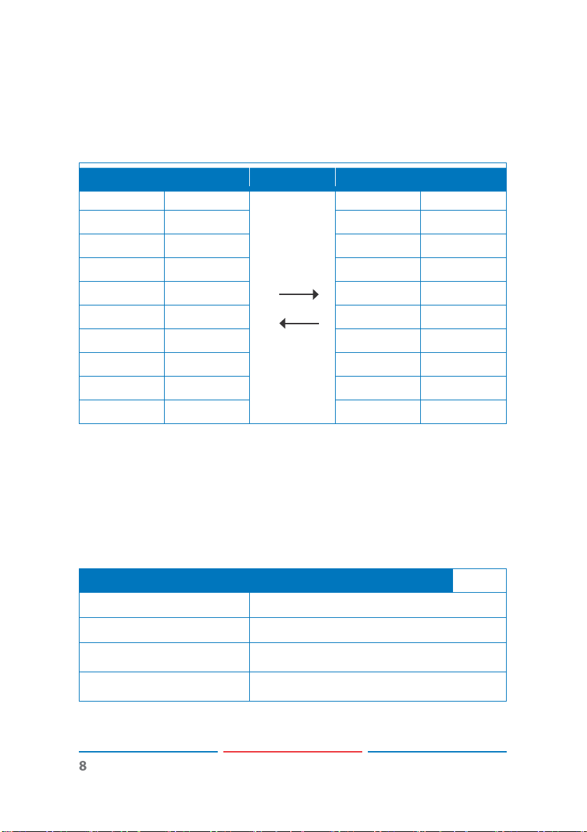
7. RS-232 PROTOCOLS
CMSDI-164
Remote Controller
PIN
Definition
PIN
Definition
1
NC 1 NC
2
TxD 2 RxD
3
RxD
3
TxD
4
NC 4 NC
5
GND
5
GND
6
NC 6 NC
7
NC 7 NC
8
NC 8 NC
9
NC 9 NC
Command
Description
poweron enter
Power ON
poweroff enter
Power OFF
portx xx enter
x= a~d output, xx=01~16 input
e.g. „port b 15― enter
Switches input 15 ot out b
7.1 Pin Assignment
Pins
definition
of modem cable
Baud Rate: 19200bps
Data bit: 8 bits
Parity: None
Stop bit: 1 bit
7.2 Commands
Page 9
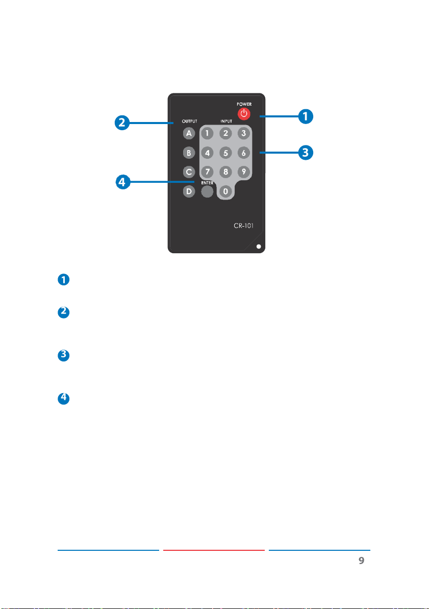
8. REMOTE CONTROL
Power
Press the button to turn on/off the unit.
OUTPUT
Press a output port from A~D
press enter to
INPUT
Press 1~16 to select the desired input source after selecting the
output then press enter to
ENTER
Press this button to
confirm
confirm
the selection.
first
then select an input number and
confirm
every output with input selection.
the selection
Page 10
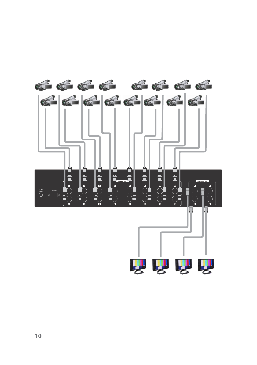
9. CONNECTION DIAGRAM
DVx16
SDI Monitorx4
Page 11

10. SPECIFICATIONS
SMPTE Standard
425M Level A & B, 424M, 292M, 259M-C
SDI Transmit ion Rates
2.970 Gbit/s and 2.970/1.001 Gbit/s
Input Ports
16 x BNC (SDI/HD-SDI/3G-SDI)
Output Ports
4 x BNC (SDI/HD-SDI/3G-SDI)
Power Supply
5V DC/ 2.6A (US/EU standards, CE/FCC/UL
certified)
ESD Protection
Human body model:
± 8 kV (air-gap discharge)
± 4 kV (contact discharge)
3G-SDI up to 100M (BELDEN 1694A)
HD-SDI up to 200M (BELDEN 1694A)
SD-SDI up to 300M (BELDEN 1694A)
Dimension (mm)
436 (W) x 132 (D) x 93 (H)
Weight (g)
2476
Chassis Material
Metal
Silkscreen Color
Black
Operating Temperature
0 ˚C~40 ˚C / 32 ˚F~104 ˚F
Storage Temperature
−20 ˚C~60 ˚C / −4 ˚F~104 ˚F
Relative Humidity
20~90 % RH (non-condensing)
Power Consumption (W)
8.5W
 Loading...